Structures, stabilities and electronic properties of graphdiyne nanoribbons
Hongcun
Bai
,
Ying
Zhu
,
Weiye
Qiao
and
Yuanhe
Huang
*
College of Chemistry, Beijing Normal University, Beijing, 100875, China. E-mail: yuanhe@bnu.edu.cn; Fax: +86 010-58802075; Tel: +86 010-58805425
First published on 6th September 2011
Abstract
The one-dimensional graphdiyne nanoribbons are studied using the self-consistent field crystal orbital method based on density functional theory in this paper. The structures, stabilities, electronic, elastic and transport properties of these nanoribbons with different edges and widths are investigated. These graphdiyne strips can be obtained from cutting the graphdiyne sheet or the carbomerization of the graphene strips. It is found that the carbomerization not only expands the structures, but also alters the stabilities, electronic, elastic and transport properties of the original systems. Here the graphdiyne nanoribbons studied are all more stable than the graphdiyne monolayer in the view of energy. Different from the graphene nanoribbons, the graphdiyne strips are all semiconductors. According to our calculations, the band gaps of the graphdiyne strips decrease monotonically as the widths increase. A quantitative relation between the band gaps and the widths of the graphdiyne nanoribbons is obtained. Moreover, we also calculate the mobilities of charge carriers for these strips based on the deformation potential theory and effective mass approach. The calculated mobilities are in the range of 102–106 cm2 V−1s−1 at room temperature. The relationship between mobilities and nanoribbon widths is different for electron and hole charge carriers. The mobilities of electrons are always larger than those of holes for these graphdiyne nanoribbons studied. Hence, the graphdiyne strips are possibly more favorable for electron transportation.
1. Introduction
Carbon is one of the most interesting elements in the periodic table. The capability of carbon atoms to form complicated networks is fundamental in organic chemistry and is the basis for the existence of life. It has long been known that there exists many carbon allotropes such as amorphous carbon, diamond and graphite, which are known from even ancient times. In the recent two decades, various fascinating carbon structures have also been discovered. In 1985, the fullerene C60 cage was discovered,1 which has created an entirely new branch of carbon chemistry. Then, the subsequent discovery of carbon nanotubes (CNTs) in 1991 has opened up a new era in materials science and nanotechnology.2 More recently, graphene, a two-dimensional (2D) honeycomb lattice monolayer, and graphene nanoribbons (NRs) have been synthesized successfully in 2004.3,4 These low-dimensional carbon nanostructures have aroused considerable attention due to their unique structural, mechanical, electronic and superconducting properties.5–11Up until now, the approaches to construct new low-dimensional carbon nanostructures have not stopped.12–17Carbon atoms can show various hybridization states (sp, sp2, sp3), but all the carbon atoms in fullerenes, CNTs and graphene present sp2 hybridization. It has been pointed out that the –C![[triple bond, length as m-dash]](https://www.rsc.org/images/entities/char_e002.gif) C– unit can be inserted into each bond A–B of a molecule for the expansion of the system.18 The structures with the –CC– unit inserted are termed “carbomers” of the original molecules. Actually, several carbomerized molecules have been synthesized successfully, such as carbomers of benzene19 and cubane.20 Moreover, if the –CC– unit is introduced into carbon nanostructures such as fullerenes, CNTs and garphene, new structures of carbon with combinations of sp and sp2carbon atoms could be formed. Several models of the carbomers of fullerenes, CNTs and graphenes have been proposed and calculated in previous studies.21–23
C– unit can be inserted into each bond A–B of a molecule for the expansion of the system.18 The structures with the –CC– unit inserted are termed “carbomers” of the original molecules. Actually, several carbomerized molecules have been synthesized successfully, such as carbomers of benzene19 and cubane.20 Moreover, if the –CC– unit is introduced into carbon nanostructures such as fullerenes, CNTs and garphene, new structures of carbon with combinations of sp and sp2carbon atoms could be formed. Several models of the carbomers of fullerenes, CNTs and graphenes have been proposed and calculated in previous studies.21–23
Very recently Li and co-workers synthesized graphdiyne,24 a 2D single-layered carbon sheet containing both sp and sp2carbon atoms. Different from any of the carbon allotropes known before, graphdiyne can be considered as a structure where one-third of the C–C bonds in the graphene are inserted with two –CC– units (di-acetylenic). It is found that the films exhibit semiconducting property. The researchers are optimistic that graphdiyne will become an important candidate in the field of electronics, semiconductors and materials. The band structure of the 2D graphdiyne layer was calculated by means of the full potential liner combination of atomic orbitals (LCAO) method based on density functional theory (DFT), indicating the semiconducting property of the graphdiyne monolayer.25 It is known that 2D graphene presents metallic properties with zero band gap, but the one-dimensional (1D) graphene NRs with armchair edges cutting the 2D graphene exhibit semiconducting properties.10 Thus the properties of the materials may be greatly influenced when the dimensionality is reduced. This arouses the questions: how do the properties change when the 2D graphdiyne sheet is cut into 1D NRs? What about the stabilities, electronic structures, elastic and transport properties of these 1D graphdiyne NRs with different widths and edges? Thus, a detailed and systematic study on the 1D NRs cutting from the graphdiyne layer would be helpful for understanding the possible structural character and electronic properties of the new carbon allotrope.
In this paper, we perform a theoretical investigation on 1D graphdiyne NRs using the self-consistent field crystal orbital (SCF-CO) method under the periodical boundary condition. The structures, electronic and transport properties of these graphdiyne NRs are calculated and compared with those of graphene NRs. We expect that this investigation could cause further attention on this new carbon structure.
2. Models and computational methods
Two patterns of the 1D graphdiyne NRs with armchair and zigzag edges (denoted as A-NRs and Z-NRs) are constructed by cutting the 2D graphdiyne as shown in Fig. 1. These two patterns are also the main structures studied for graphene NRs and carbon nanotubes. We thus can compare our results with those obtained for the graphene NRs and carbon nanotubes. The size of the unit cells of 1D graphdiyne NRs is indexed by the number N. The larger the N, the larger the unit cells of the 1D NRs. The widths of the 1D NRs increase with the number N. Here, a 1D graphdiyne NR is denoted as A-NR-N or Z-NR-N. Taking N = 1–12, we can study the effect of the quantum confinement for the 1D graphdiyne NRs with widths from 1–10 nm. The dangling bonds at the edges are terminated by hydrogen atoms in our model, which is similar to the treatment for the graphene NRs.10,23 The unit cell contains (18N + 10) carbon atoms and four hydrogen atoms for A-NR-N, but contains (18N + 20) carbon atoms and eight hydrogen atoms for Z-NR-N. For the A-NRs, the symmetries are C2v and D2h for N = odd and even, respectively. As for the Z-NRs, the symmetries are reversed. Here, 2D graphdiyne is also calculated for the comparison. A unit cell of 2D graphdiyne contains 18 carbon atoms and is also shown in Fig. 1(b). C1, C2 and C3 are the three non-equivalent carbon atoms.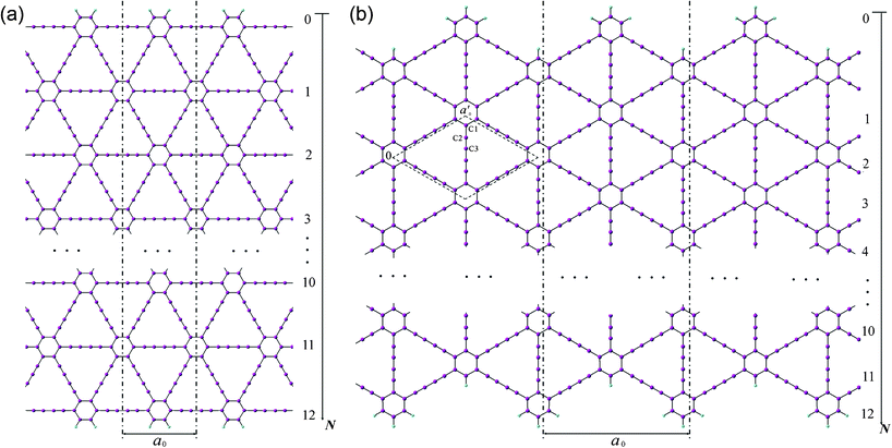 | ||
| Fig. 1 Models of the 1D graphdiyne nanoribbons with (a): armchair edges (A-NRs); (b) zigzag edges (Z-NRs). The unit cell of the 2D graphdiyne is labeled with the dashed rhombus in Fig. 1(b). a0 and a′0 are the lattice constants of the 1D NRs and 2D graphdiyne, respectively. | ||
The band structures and electronic properties are calculated by means of the SCF-CO method based on DFT with full structural optimization and CRYSTAL06 program26 for all the models studied. In the geometric optimization, symmetry constraint is always adopted. The exchange–correlation functional proposed by Perdew, Burke and Ernzerhof (PBE)27,28 and a double-ζ plus polarization basis set 6–21 G(d,p)29 which is implemented in the program for solid-state calculations, are used in our DFT SCF-CO calculations. In the first Brillouin zone 40 and 20 × 20 k-point samplings are adopted for 1D and 2D structures, respectively and default values of convergence criteria in CRYSTAL06 are used (total energy change less than 10−6 hartree/cell and geometry optimization with maximum force less than 0.00045 hartree/bohr).26
3. Results and discussions
3.1 Structures and stabilities
The widths of A-NRs and Z-NRs are in the range 1.1–10.1 nm and 1.2–6.4 nm when N = 1–12, respectively. For the armchair strips, the optimized lattice length a0 is 9.494 Å in A-NR-1, and then it gradually increases to 9.496 Å in A-NR-12, close to the lattice length a′0 9.497 Å in the 2D graphdiyne layer at the same computational level. For zigzag ribbons, as N increase from 1 to 12, the lattice length a0 increases from 16.447 Å to 16.450 Å that is closed to the corresponding distance of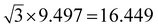 Å in the 2D layer.
The lengths of four non-equivalent carbon–carbon bonds C1–C1, C1–C2, C2–C3 and C3–C3 in the 2D graphdiyne layer are 1.440, 1.400, 1.239 and 1.341 Å, respectively. The C1–C1 bonds can be seen as the sp2–sp2 bonds, similar to that in the graphene (1.431 Å) at the same computational level. It is noteworthy that here the C3–C3 bonds are obviously shorter than the typical single bond (1.53 Å), while the C2–C3 bonds are somewhat longer than the typical triple bond (1.20 Å). As for the C–C bond in 1D graphdiyne NRs, the lengths of the bonds in the middle part of the ribbons gradually reach the values of those in the 2D graphdiyne with the increase of the ribbon width. The average of the bonds indicates that the carbomerized structures are still conjugated systems for the graphdiyne and the 1D graphdiyne NRs. For the C–C bonds at the edge of the 1D graphdiyne NRs, the bond lengths of C1–C1, C1–C2, C2–C3 and C3–C3 are about 1.388, 1.405, 1.238 and 1.345 Å in A-NRs and 1.399, 1.410, 1.236 and 1.347 Å in Z-NRs, respectively.
As the 1D graphdiyne ribbons have different chemical compositions due to the passivation of the dangling bonds with hydrogen atoms, we adopt the approach customarily used in binary phase thermodynamics to account for chemical composition and utilized previously to analyze the relative stability of graphene NRs30 and endohedral silicon nanowires.31 As for the graphdiyne nanoribbons, we also define the Gibbs free energy, δG, with respect to graphene and molecular hydrogen through the equation:
| δG = −E(coh) + xHμH + (1 − xH)μC | (1) |
| NR | Width | δG | E g |
|---|---|---|---|
| A-NR-1 | 1.07 | 0.598 | 0.971 |
| A-NR-2 | 1.89 | 0.672 | 0.781 |
| A-NR-3 | 2.72 | 0.707 | 0.686 |
| A-NR-4 | 3.54 | 0.727 | 0.626 |
| A-NR-5 | 4.36 | 0.741 | 0.585 |
| A-NR-6 | 5.18 | 0.749 | 0.558 |
| A-NR-7 | 6.01 | 0.756 | 0.536 |
| A-NR-8 | 6.82 | 0.762 | 0.531 |
| A-NR-9 | 7.66 | 0.766 | 0.517 |
| A-NR-10 | 8.46 | 0.770 | 0.509 |
| A-NR-11 | 9.30 | 0.772 | 0.493 |
| A-NR-12 | 10.12 | 0.775 | 0.484 |
| Z-NR-1 | 1.23 | 0.520 | 1.538 |
| Z-NR-2 | 1.66 | 0.600 | 1.181 |
| Z-NR-3 | 2.18 | 0.645 | 0.989 |
| Z-NR-4 | 2.61 | 0.673 | 0.868 |
| Z-NR-5 | 3.13 | 0.693 | 0.785 |
| Z-NR-6 | 3.56 | 0.708 | 0.725 |
| Z-NR-7 | 4.08 | 0.719 | 0.680 |
| Z-NR-8 | 4.50 | 0.728 | 0.646 |
| Z-NR-9 | 5.03 | 0.735 | 0.618 |
| Z-NR-10 | 5.45 | 0.741 | 0.595 |
| Z-NR-11 | 5.98 | 0.746 | 0.577 |
| Z-NR-12 | 6.40 | 0.750 | 0.561 |
From the table, we can see that the values of Gibbs free energies for the 1D graphdiyne NRs are in the range of 0.520–0.775 eV. δG of 2D graphdiyne layer is calculated to be 0.803 eV. Thus the Gibbs free energies of the graphdiyne NRs are smaller than that of the 2D layer. Hence the strip form of this carbomerized structure is more stable than the planar counterpart, which is similar to the case in biphenylene sheets.32 For a comparison, the δG of a armchair graphene NR with a width of about 2.7 nm is also calculated. The obtained δG is 0.008 eV and very close to the result in ref. 30. Furthermore, the stabilities of these graphdiyne NRs decrease as their widths increase. When N = 12, δG of the armchair and zigzag graphdiyne NRs respectively are 0.775 and 0.750 eV, which are very close to 0.803 eV for the 2D graphdiyne. Additionally, it can also be seen that the Z-NRs are a little more stable than the A-NRs. This fact is also different from the case in the graphene NRs, since the graphene NRs' edges had little influence on their relative stabilities according to Barone and co-authors' DFT calculations.30 On the other hand, if one considers the energy necessary for the formation of the edges, the armchair graphene NRs are more stable than the zigzag structures based on the previous calculations.33,34 This is contrary to the case in the graphdiyne NRs, because Z-NRs are more stable here. These discussions above imply that the carbomerizations of graphene NRs alter the order of relative stabilities for the two different strip forms.
For the all carbon systems, Ecoh of graphene is calculated to be 7.973 eV/atom with the same method, and close to previous DFT results of 7.70 eV/atom with HSE and 8.08 eV/atom with PBE methods.30,35 According to eqn (1), δG of the 2D graphene and graphdiyne are zero and 0.803 eV respectively. δG of several carbon allotropes are also calculated with the same method. The obtained values of δG are −0.022, −0.008, 0.114 and 0.364 eV respectively for diamond, graphite, CNT (6, 6) and C60. Thus the 2D graphdiyne is less stable than the mentioned carbon allotropes in the viewpoint of energy. δG of the graphdiyne is 0.803 eV larger than that of the graphene, hence the carbomerization would decrease the stability of the original system. Nevertheless, graphdiyne is still more stable than the 1D carbon chain with δG of 1.037 eV at the same computational level, and the carbon chains have been observed in the experiment.16,36
3.2 Band structures and electronic properties
The calculated band structures of 1D graphdiyne NRs are presented in Fig. 2. From the band structures, it can be seen clearly that both the A-NRs and the Z-NRs all have a direct band gap (Eg) at the Γ point. Here Eg is the energy difference between the top of the highest occupied band (HOB) and the bottom of the lowest unoccupied band (LUB) and is also shown in Table 1. Therefore the 1D graphdiyne NRs are all semiconductors. Thus, the semiconducting property of these graphdiyne NRs is edge-independent. However, previous studies have shown that the armchair graphene NRs are all semiconductors, but the zigzag graphene NRs exhibit metallic properties.10 Thus the band gap opening for the zigzag graphene NRs could be achieved by carbomerzation. These manifest in that the carbomerization alters not only the structures but also the electronic properties of the original 1D graphene NRs. This unique feature may make this new single-layered sheet more suitable for semiconductor materials in nanoelectronics. Graphene is a material with unique properties for building electronic devices, but the absence of a band gap limits its application in the semiconductor industry, because usually semiconducting properties are required in some nanodevices nowadays.37,38 Thus the graphdiyne may open another promising window to the nanoelectronics. | ||
| Fig. 2 Band structures (left) and Eg–W relationship (right) of the graphdiyne NRs with N = 1–12. (a) A-NRs; (b) Z-NRs. | ||
The band gaps of the 1D graphdiyne NRs as a function of their widths are also shown in Fig. 2. We can see that the band gaps of these graphdiyne NRs decrease as their widths increase. The band gaps in A-NR-1 and Z-NR-1 are 0.971 and 1.538 eV, respectively. As the widths of the ribbons increase, Eg decreases to about 0.5 eV for both A-NR-12 and Z-NR-12, close to 0.441 eV for the 2D graphdiyne layer. Furthermore, it is found that Egs of the graphdiyne NRs are presented to be an inverse power law as a function of their widths (see Fig. 2). Although this behavior is similar to the situation in the armchair graphene NRs,30 the band gaps have no periodical changes with the width of the graphdiyne NRs. Since Clar's aromatic sextet theory is a simple and powerful tool to study π-conjugated systems and has been used for CNTs and graphene NRs,11,39,40 we would like to investigate graphdiyne NRs also from the view of Clar's theory. Graphdiyne and its NRs are composed of 6- and 18-membered rings, in which no two 6-membered rings are adjacent. Thus all the 6-membered rings of graphdiyne are so-called benzenoid according to the Clar's theory. Each unite cell contains N + 2 benzenoid 6-membered rings for the zigzag graphdiyne NR Z-NR-N, but N + 1 benzenoid 6-membered rings for the armchair graphdiyne NR A-NR-N. Thus each unite cell of the Z-NR-N always has more benzenoid 6-membered rings than that of the A-NR-N by one, indicating that the Z-NR-N has a larger Eg and higher chemical reactivity41 than A-NR-N.
In order to get a quantitative scaling of Eg with respect to the widths of the graphdiyne NRs, we fit the corresponding data to the equation Eg = aW−b (in eV), similar to the treatment for graphene NRs,30 where W is the width (in nm) of the graphdiyne NRs. The values of a and b obtained are 0.945 and 0.302 for A-NRs, 1.604 and 0.593 for Z-NRs, respectively.
Here, some points are worth noting. Firstly, the values of Eg decrease monotonically as the widths increase for both the armchair and zigzag 1D graphdiyne NRs. However, the variations of Eg for the armchair graphene NRs exhibit three distinct groups in a 3-fold periodic pattern.11,30,42 Hence the carbomerization leads to a quite different Eg–W relationship between the graphdiyne NRs and graphene NRs. Secondly, in equation Eg = aW−b, the exponent b reflects the sensitive degree of the width changes for the graphdiyne NRs. From Fig. 2, we can see that the values of b are 0.302 and 0.593 for A-NRs and Z-NRs, respectively. Furthermore, the band gaps of the armchair graphene NRs with widths of about 2.5 and 2.7 nm are also calculated. They are 0.376 and 0.065 eV and in accordance with the results of the Barone's DFT calculations.30 The DFT calculations show that the values of the exponent b are 0.872–1.097 for the graphene NRs.30 Obviously, the b exponents of the graphdiyne NRs are quite smaller than those of the graphene NRs, which suggests that the band gaps of the graphdiyne NRs change more smoothly with the changes of their widths than those of graphene NRs. This behavior would be favorable for accurate modulation of the band gaps by tuning the ribbon widths for the 1D graphdiyne NRs.
3.3 Mobilities and conductivities
Since the mobility of the charge carrier is one of the central issues for nanoelectronics,43 we calculate the mobility and the conductivity of the graphdiyne NRs for better understanding of their transport properties. Here a simple model based on the deformation potential (DP) theory and effective mass approach is adopted. This model has been used for 1D polymers,44,45fullerene nanostructures,46 CNTs,47,48graphene NRs49 and DNA stacks.50 With the DP and effective mass approximation, the charge carrier mobility μ of 1D crystal can be expressed as44,50: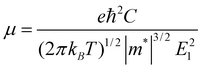 | (2) |
 for electrons and holes, respectively. Here m* can be obtained from the energy curves in Fig. 2. The deformations of the lattice constants 0%, ±0.5%, ±1.0% and ±1.5% are also calculated to get C and E1. From the changes of the top of HOB and the bottom of LUB with Δ, we get two straight lines with a correlation coefficient >0.99. Then we derived E1v and E1c respectively for hole and electron carriers of these 1D semiconductors from the slope of the straight lines. The stretching modulus C can be obtained by fitting the energy curve as a function of lattice constants with correlation coefficient >0.99 and using C = a0 (∂2E/∂a2)|a = a0.
The calculated electron and hole mobilities for the graphdiyne NRs at room temperature T = 298 K are shown in Table 2. For A-NRs, the electron and hole mobilities (μe and μh) are in the range 104–106 cm2 V−1s−1 and 103–104 cm2 V−1s−1 for electrons and holes, respectively. As for Z-NRs, they are 102–105 cm2 V−1s−1 and 102–103 cm2 V−1s−1 for electrons and holes, respectively. In addition, the holes have smaller mobility than the electrons for the same 1D graphdiyne strip. Since the difference of the effective mass between electrons and holes (me* and mh*) is small, the larger mobility of electrons is mainly due to smaller E1c for the same graphdiyne NR. The DP constants E1c and E1v are related to the band-edge shift induced by the scattering of electrons or holes from the acoustic phonon, thus the different electron and hole mobilities here are mainly coming from the different scattering behaviors in these graphdiyne NRs for electrons and holes. The mobility of these graphdiyne NRs increases as their width increases, even as high as 106 cm2 V−1s−1, the same order as those in graphene NRs49 and CNTs.47,51 Thus the graphdiyne NRs are also candidates for high mobility materials. Moreover, the mobilities of charge carriers for the graphdiyne NRs increase monotonically with the increase of their width. Therefore, the charge carriers in the graphdiyne NRs would have different behavior from those in the graphene NRs, because the mobilities in the graphene NRs show the distinct alternating change with the increase of widths for both electrons and holes.49 The carbomerization thus also results in the different transportation properties from the original graphene NRs.
| NR | C | m e * | m h * | E 1v | E 1c | μ e | μ h | σ | Y |
|---|---|---|---|---|---|---|---|---|---|
| A-NR-1 | 190 | 0.103 | 0.110 | 5.678 | 1.323 | 2.616 × 10⁴ | 1.291 × 10³ | 3.284 × 10⁻³ | 834 |
| A-NR-2 | 289 | 0.108 | 0.111 | 5.427 | 0.935 | 7.412 × 10⁴ | 2.101 × 10³ | 2.367 × 10⁻¹ | 721 |
| A-NR-3 | 385 | 0.110 | 0.116 | 5.297 | 0.752 | 1.490 × 10⁵ | 2.761 × 10³ | 2.209 | 667 |
| A-NR-4 | 485 | 0.111 | 0.115 | 5.214 | 0.650 | 2.485 × 10⁵ | 3.644 × 10³ | 9.404 | 647 |
| A-NR-5 | 541 | 0.113 | 0.115 | 5.159 | 0.580 | 3.386 × 10⁵ | 4.174 × 10³ | 2.373 × 101 | 584 |
| A-NR-6 | 694 | 0.112 | 0.115 | 5.178 | 0.529 | 5.259 × 10⁵ | 5.262 × 10³ | 5.302 × 101 | 631 |
| A-NR-7 | 745 | 0.116 | 0.115 | 5.141 | 0.483 | 6.445 × 10⁵ | 5.770 × 10³ | 8.829 × 101 | 584 |
| A-NR-8 | 859 | 0.113 | 0.118 | 5.150 | 0.475 | 7.908 × 10⁵ | 6.389 × 10³ | 1.044 × 10² | 593 |
| A-NR-9 | 999 | 0.116 | 0.117 | 4.928 | 0.414 | 1.181 × 10⁶ | 8.163 × 10³ | 1.851 × 10² | 614 |
| A-NR-10 | 1050 | 0.115 | 0.119 | 4.974 | 0.408 | 1.282 × 10⁶ | 8.228 × 10³ | 2.131 × 10² | 585 |
| A-NR-11 | 1164 | 0.118 | 0.115 | 4.827 | 0.402 | 1.413 × 10⁶ | 1.023 × 10⁴ | 2.981 × 10² | 590 |
| A-NR-12 | 1280 | 0.117 | 0.115 | 4.724 | 0.386 | 1.702 × 10⁶ | 1.164 × 10⁴ | 3.936 × 10² | 596 |
| Z-NR-1 | 137 | 0.454 | 0.325 | 3.691 | 1.990 | 8.977 × 10² | 4.302 × 10² | 3.297 × 10⁻⁹ | 523 |
| Z-NR-2 | 192 | 0.294 | 0.244 | 3.955 | 1.772 | 3.050 × 10³ | 8.103 × 10² | 7.370 × 10⁻⁶ | 547 |
| Z-NR-3 | 252 | 0.227 | 0.208 | 4.122 | 1.613 | 7.089 × 10³ | 1.242 × 10³ | 5.040 × 10⁻⁴ | 544 |
| Z-NR-4 | 310 | 0.195 | 0.183 | 4.239 | 1.482 | 1.304 × 10⁴ | 1.757 × 10³ | 7.808 × 10⁻³ | 560 |
| Z-NR-5 | 368 | 0.176 | 0.173 | 4.178 | 1.379 | 2.091 × 10⁴ | 2.337 × 10³ | 5.153 × 10⁻² | 554 |
| Z-NR-6 | 427 | 0.163 | 0.163 | 4.432 | 1.290 | 3.094 × 10⁴ | 2.615 × 10³ | 2.086 × 10⁻¹ | 566 |
| Z-NR-7 | 486 | 0.155 | 0.160 | 4.491 | 1.213 | 4.295 × 10⁴ | 3.004 × 10³ | 5.925 × 10⁻¹ | 562 |
| Z-NR-8 | 545 | 0.150 | 0.157 | 4.539 | 1.179 | 5.357 × 10⁴ | 3.374 × 10³ | 1.314 | 570 |
| Z-NR-9 | 604 | 0.150 | 0.151 | 4.618 | 1.119 | 6.608 × 10⁴ | 3.845 × 10³ | 2.511 | 566 |
| Z-NR-10 | 664 | 0.144 | 0.153 | 4.654 | 1.066 | 8.482 × 10⁴ | 4.068 × 10³ | 4.525 | 574 |
| Z-NR-11 | 722 | 0.142 | 0.150 | 4.685 | 1.018 | 1.040 × 10⁵ | 4.483 × 10³ | 7.201 | 569 |
| Z-NR-12 | 781 | 0.140 | 0.151 | 4.712 | 0.975 | 1.247 × 10⁵ | 4.790 × 10³ | 1.091 × 101 | 575 |
From Table 2, it can be seen that A-NR-N has larger mobility than Z-NR-N for the same charge carriers, especially, one order larger or more for electron mobility. Since the width of A-NR-N is different from that of Z-NR-N for the same number N, we also give the mobility-width relationship of the graphdiyne NRs in Fig. 3. The curves in Fig. 3 show that both the electron and the hole mobilities of the armchair NRs are still larger than those of zigzag NRs with the same widths. Therefore, it is the structural difference that results in the difference of mobilities for the two different patterns of 1D graphdiyne NRs. Moreover, wider graphdiyne NRs are more favorable for the transportation of charge carriers.
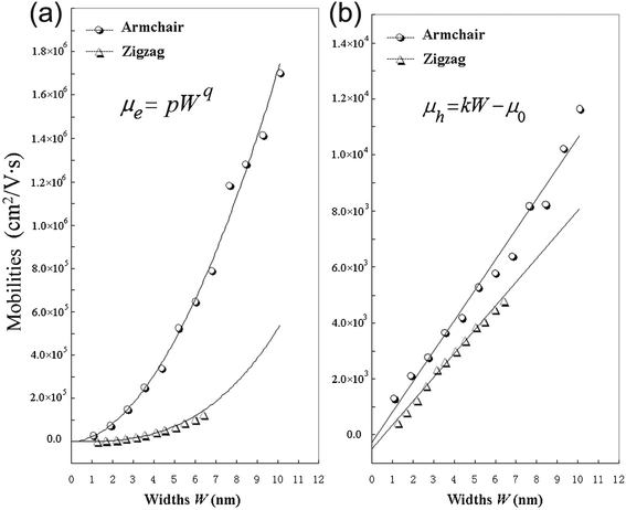 | ||
| Fig. 3 Calculated mobilities of charge carriers for the graphdiyne nanoribbons. (a) Electrons; (b) Holes. | ||
As shown in Fig. 3, it is found that the electron mobility is dependent on W with equation μe = pWq for these graphdiyne NRs. However, it is interesting that the hole mobility is linear-scale with the change of W based on the equation μh = kW − μ0 for both armchair and zigzag graphdiyne NRs. The correlation coefficients are all ≥0.99 for fitting the curves in Fig. 3. The obtained corresponding constants are pA-NR = 22784.8, pZ-NR = 682.8, qA-NR = 1.876, qZ-NR = 2.881, kA-NR = 1084.4 and kZ-NR = 846.6. Therefore, the structural difference also leads to different dependence of the mobilities on the widths for different types of the graphdiyne NRs. Although the semiconducting property of the 1D graphdiyne NRs is edge-independent, the transport properties are different for the graphdiyne NRs with different edges. Additionally, the mobility of electrons is always larger than that of holes for the same graphdiyne nanoribbon. Hence, the graphdiyne NRs studied are more favorable to the electron movement.
The conductivity σ of the graphdiyne NRs in the intrinsic state can be expressed as44:
| σ = enμe + epμh = σ0 exp (−Eg/2kBT) | (3) |
3.4 Young’s moduli
Young’s modulus (Y) can be used to describe the elastic stiffness of the 1D graphdiyne NRs. We calculate the Young modulus using the second derivative of the energy (E) of a unit cell with respect to the axial strain ε along the tube axis: , where V0 is the volume of a unite cell and ε is a small deformation of the lattice constant. Here the interlayer distance is taken as 3.4 Å to evaluate the volume, which is the Van der Waals distance between two carbon atoms. To obtain the values of Young’s moduli, we calculate the energies of the unit cell with the deformations of the lattice constant 0%, ±0.5%, ±1.0% and ±1.5%. The curve of the energy as a function of lattice constant deformations is drawn with the correlation coefficient >0.99. Then d2E/dε2 is obtained from the second derivative at zero strain. The calculated Young’s moduli are also listed in Table 2.
From Table 2, the Young’s moduli of these NRs are in the range of 584–834 GPa for the A-NRs and 523–575 GPa for Z-NRs, respectively. Thus the elastic properties of the graphdiyne NRs with different edges and widths don’t present much difference. For comparison, the Young’s modulus of the armchair graphene NRs with the width of about 2.7 nm is calculated to be 1052 GPa at the same computational level. We also calculate the Young’s modulus of single-walled carbon nanotubes (SWCNTs) (6, 6) and (12, 0), getting Y ≈ 1000 GPa for the both tubes. This value is also close to those obtained by the calculations and the experiment.6,52 Hence, the graphene NRs have almost same Young’s moduli as the SWCNTs. Obviously, the graphdiyne NRs have weaker resistance to the strain along the axis direction than the graphene NRs and SWCNTs. A-NR-1 with narrowest width has the largest Young’s modulus among these 1D NRs. From Fig. 1, it can be understood that A-NR-1 has also the largest atom distribution density among these 1D NRs. Compared to the graphene NRs and SWCNTs, the smaller Young’s moduli of these graphdiyne NRs are mainly derived from the sparse net structure of carbon atom distribution for the graphdiyne strips with the introduced –CC– units.
4. Conclusion
The two patterns of 1D graphdiyne NRs (A-NRs and Z-NRs) with various widths up to 10 nm have been investigated using a SCF-CO method based on DFT calculations. These 1D graphdiyne NRs can be obtained from the carbomerization of the graphene NRs or by cutting the 2D graphdiyne sheet.According to the calculated cohesive energies, the 1D graphdiyne NRs studied are all more stable than the 2D graphdiyne slab in view of energy. Different from the graphene NRs, the graphdiyne NRs with zigzag edges are more stable than the armchair structures. Since the 2D graphdiyne has been synthesized, we may expect that the 1D graphdiyne NRs with more stable structures would be observed experimentally in the near future.
The calculations show that both the graphdiyne A-NRs and Z-NRs are all semiconductors. This is different from graphene NRs, for which the semiconducting or metallic properties are dependent on their edges. Therefore the structure difference resulting from the carbomerization alters not only the stabilities but also the electronic properties of the original 1D graphene NRs. The relationship of the band gaps and the graphdiyne NR widths is found to be Eg = aW−b, which may be used to tune a required band gap through change of the NR widths.
We also calculate the mobilities of charge carriers for the graphdiyne NRs based on the DP theory and effective mass approach. The calculated mobilities are in the range of 102–106 cm2 V−1s−1 at room temperature. Thus the graphdiyne NRs should be candidates for high mobility materials. The A-NRs have larger mobilities than the Z-NRs for both electrons and holes with the same NR widths. The mobility-width relation is different for the different charge carriers, μe = pWq for electrons, but μh = kW − μ0 for holes. Moreover, the mobilities of electrons are larger than those of holes for all the 1D graphdiyne NRs. Hence, the graphdiyne NRs studied are possibly more favorable to be materials for electron transportation.
The calculated values of Young moduli for most of the graphdiyne NRs are about half of those for the graphene NRs and SWCNTs, which indicates that the graphdiyne NRs are softer than the graphene NRs and SWCNTs.
Acknowledgements
This work is supported by the National Natural Science Foundation of China (Grant No. 20873009).References
- H. W. Kroto, J. R. Heath, S. C. O'Brien, R. F. Curl and R. E. Smalley, Nature, 1985, 318, 162–163 CrossRef CAS.
- S. Iijima, Nature, 1991, 354, 56–58 CrossRef CAS.
- K. S. Novoselov, A. K. Geim, S. V. Morozov, D. Jiang, Y. Zhang, S. V. Dubonos, I. V. Grigorieva and A. A. Firsov, Science, 2004, 306, 666–669 CrossRef CAS.
- L. Jiao, L. Zhang, X. Wang, G. Diankov and H. Dai, Nature, 2009, 458, 877–880 CrossRef CAS.
- Y. E. L. Bai, L. Fan, M. Han, X. Zhang and S. Yang, J. Mater. Chem., 2011, 21, 819–823 RSC.
- J. P. Lu, Phys. Rev. Lett., 1997, 79, 1297–1300 CrossRef CAS.
- H. Bai, R. Du, W. Qiao and Y. Huang, J. Mol. Stru.: Theochem, 2010, 961, 42–47 CrossRef CAS.
- L. Huang, B. Wu, G. Yu and Y. Liu, J. Mater. Chem., 2011, 21, 919–929 RSC.
- G. Wang and Y. Huang, J. Phys. Chem. C, 2008, 112, 9128–9132 CAS.
- K. Nakada, M. Fujita, G. Dresselhaus and M. S. Dresselhaus, Phys. Rev. B, 1996, 54, 17954–17961 CrossRef CAS.
- T. Wassmann, A. P. Seitsonen, A. M. Saitta, M. Lazzeri and F. Mauri, J. Am. Chem. Soc., 2010, 132, 3440–3451 CrossRef CAS.
- D. C. Elias, R. R. Nair, T. M. G. Mohiuddin, S. V. Morozov, P. Blake, M. P. Halsall, A. C. Ferrari, D. W. Boukhvalov, M. I. Katsnelson, A. K. Geim and K. S. Novoselov, Science, 2009, 323, 610–613 CrossRef CAS.
- Y. Wang, Y. Huang, B. Yang and R. Liu, Carbon, 2008, 46, 276–284 CrossRef CAS.
- S. Tongay, R. T. Senger, S. Dag and S. Ciraci, Phys. Rev. Lett., 2004, 93, 136404(1–4) CrossRef.
- R. H. Baughman, Science, 2006, 312, 1009–1010 CrossRef CAS.
- C. Jin, H. Lan, L. Peng, K. Suenaga and S. Iijima, Phys. Rev. Lett., 2009, 102, 205501(1–4) Search PubMed.
- Y. Wang, Y. Huang and R. Liu, Chem.–Eur. J., 2006, 12, 3610–3616 CrossRef CAS.
- R. Chauvin, Tetrahedron Lett., 1995, 36, 397–400 CrossRef CAS.
- C. Zou, C. Duhayon, V. Maraval and R. Chauvin, Angew. Chem., 2007, 119, 4415–4419 CrossRef.
- P. Manini, W. Amrein, V. Gramlich and F. Diederich, Angew. Chem., Int. Ed., 2002, 41, 4339–4343 CrossRef CAS.
- P. D. Jarowski, F. Diederich and K. N. Houk, J. Org. Chem., 2005, 70, 1671–1678 CrossRef CAS.
- V. R. Coluci, S. F. Braga, S. B. Legoas, D. S. Galvao and R. H. Baughman, Nanotechnology, 2004, 15, S142–149 CrossRef CAS.
- R. H. Baughman and H. Eckhardt, J. Chem. Phys., 1987, 87, 6687–6699 CrossRef CAS.
- G. Li, Y. Li, H. Liu, Y. Guo, Y. Li and D. Zhu, Chem. Commun., 2010, 46, 3256–3258 RSC.
- N. Narita, S. Nagai, S. Suzuki and K. Nakao, Phys. Rev. B, 1998, 58, 11009–11014 CrossRef CAS.
- R. Dovesi, V. R. Saunders, C. Roetti, R. Orlando, C. M. Zicovich-Wilson, F. Pascale, B. Civalleri, K. Doll, N. M. Harrison, I. J. Bush, Ph. D'Arco and M. Llunell, CRYSTAL06 User's Manual, University of Torino, Torino, 2006 Search PubMed.
- J. P. Perdew, K. Burke and M. Ernzerhof, Phys. Rev. Lett., 1996, 77, 3865–3868 CrossRef CAS.
- J. P. Perdew, K. Burke and M. Ernzerhof, Phys. Rev. Lett., 1997, 78, 1396 CrossRef CAS.
- R. Dovesi, M. Causa, R. Orlando, C. Roetti and V. R. Saunders, J. Chem. Phys., 1990, 92, 7402–7411 CrossRef CAS.
- V. Barone, O. Hod and G. E. Scuseria, Nano Lett., 2006, 6, 2748–2754 CrossRef CAS.
- T. Dumitric, M. Hua and B. I. Yakobson, Phys. Rev. B, 2004, 70, 241303(1–4) Search PubMed.
- M. A. Hudspeth, B. W. Whitman, V. Barone and J. E. Peralta, ACS Nano, 2010, 4, 4565–4570 CrossRef CAS.
- T. Kawai, Y. Miyamoto, O. Sugino and Y. Koga, Phys. Rev. B, 2000, 62, 16349–16352 CrossRef.
- S. Okada, Phys. Rev. B, 2008, 77, 041408(1–4) Search PubMed.
- J. C. Boettger and S. B. Trickey, Phys. Rev. B, 2007, 75, 121402R(1–3) Search PubMed.
- S. Szafert and J. A. Gladysz, Chem. Rev., 2003, 103, 4175–4205 CrossRef CAS.
- A. Savchenko, Science, 2009, 323, 589–590 CrossRef CAS.
- G. Gui, J. Li and J. Zhong, Phys. Rev. B, 2008, 78, 75435(1–6) CrossRef.
- T. Wassmann, A. P. Seitsonen, A. M. Saitta, M. Lazzeri and F. Mauri, Phys. Rev. Lett., 2008, 101, 096402(1–4) CrossRef.
- M. Baldoni, D. Selli, A. Sgamellotti and F. Mercuri, J. Phys. Chem. C, 2009, 113, 862–866 CAS.
- J. Aihara, J. Phys. Chem. A, 1999, 103, 7487–7495 CrossRef CAS.
- Y. Son, M. L. Cohen and S. G. Louie, Phys. Rev. Lett., 2006, 97, 216803(1–4) Search PubMed.
- S. Hong and S. Myung, Nat. Nanotechnol., 2007, 2, 207–208 CrossRef CAS.
- Y. Huang and R. Liu, Chem. Res. Chi. Univ., 1991, 7, 107–113 CAS.
- G. Wang and Y. Huang, J. Phys. Chem. Solids, 2007, 68, 2003–2007 CrossRef CAS.
- H. Bai, Y. Ai and Y. Huang, Phys. Status Solidi B, 2011, 248, 969–973 CrossRef CAS.
- G. Wang and Y. Huang, J. Phys. Chem. Solids, 2008, 69, 2531–2534 CrossRef CAS.
- N. Sa, G. Wang, B. Yin and Y. Huang, Phys. E., 2008, 40, 2396–2399 CrossRef CAS.
- M. Long, L. Tang, D. Wang, L. Wang and Z. Shuai, J. Am. Chem. Soc., 2009, 131, 17728–17729 CrossRef CAS.
- F. B. Beleznay, F. Bogar and J. Ladik, J. Chem. Phys., 2003, 119, 5690–5695 CrossRef CAS.
- B. Xu, Y. D. Xia, J. Yin, X. G. Wan, K. Jiang, A. D. Li, D. Wu and Z. G. Liu, Appl. Phys. Lett., 2010, 96, 183108(1–3) Search PubMed.
- A. Krishnan, E. Dujardin, T. W. Ebbesen, P. N. Yianilos and M. M. J. Treacy, Phys. Rev. B, 1998, 58, 14013–14019 CrossRef CAS.
| This journal is © The Royal Society of Chemistry 2011 |