Symmetric and reversible solid oxide fuel cells
Juan Carlos
Ruiz-Morales
*a,
David
Marrero-López
*b,
Jesús
Canales-Vázquez
c and
John T. S.
Irvine
d
aDpto. Química Inorgánica. Universidad de La Laguna, Avda. Astrofísico Francisco Sánchez s/n, CP, 38200, Tenerife, Spain. E-mail: jcruiz@ull.es
bDpto. de Física Aplicada I, Universidad de Málaga, 29071-Málaga, Spain. E-mail: damarre@uma.es
cInstituto de Energías Renovables, Parque Científico y Tecnológico de Albacete, Universidad de Castilla la Mancha, 02006, Albacete, Spain. E-mail: Jesus.Canales@uclm.es
dSchool of Chemistry, University of St Andrews, North Haugh, St Andrews, UK KY16 9ST. E-mail: jtsi@st-and.ac.uk
First published on 25th October 2011
Abstract
In the past few years a novel concept of Solid Oxide Fuel Cells (SOFC) has been developed: the symmetrical Solid Oxide Fuel Cells (SSOFC). In this configuration, the same electrode material is used as anode and cathode. Several state-of-the-art SOFC electrode materials have been tested and optimised to operate in such a novel configuration, as is the case of the lanthanum chromites traditionally used as interconnect materials, lanthanum chromium manganites and strontium titanates generally used as anodes and lanthanum manganites typically used as cathodes. Fuel cell performances of approximately 800 mW cm−2 and ∼500 mW cm−2 under H2 and CH4 atmospheres have been obtained using some of these materials in symmetric configuration. Moreover, promising performances have also been reported for interconnect-based materials under city gas containing the impurity H2S. An interesting feature of the compositions evaluated is their potential use as symmetrical electrodes for Solid Oxide Electrolysis Cells (SOEC) with efficiencies in the range of the conventional SOEC systems, i.e. LSM-YSZ/YSZ/Ni-YSZ. Hence, they may be considered all-in-one Symmetric and Reversible SOFCs (SR-SOFCs) with significant advantages compared to traditional configurations, regarding both fabrication and maintenance/operation. In this review, we provide an insight into the most common materials tested as symmetrical electrodes for SOFCs and SOECs, electrolytes employed, configurations tested, new fabrication processes and procedures for microstructural engineering.
Introduction
The increase in power demand, greater greenhouse gas emissions and the likely demise of fossil fuel supplies within decades have led to the development and integration of green technologies mainly based on renewable sources. As a complementary technology to renewable energies, fuel cells appear as reliable systems for highly efficient power production.1 These systems are robust, modular, and quiet, producing electricity, heat and water as the final by-product when hydrogen is used as the fuel and therefore they can be considered zero-emission systems.There are several types of fuel cells, one type operating at relatively high temperatures being known as Solid Oxide Fuel Cells (SOFCs).1 The high operating temperatures (750–950 °C) of SOFCs cause problems associated with component degradation, although high temperatures also facilitate the possibility of hydrocarbon internal reforming and hence help to avoid the use of costly and bulky external reformers. In addition, high temperatures imply more favourable thermodynamic conditions for steam electrolysis, which is rather convenient for the development of Solid Oxide Electrolysis Cells (SOECs) with almost 100% electrical-to-hydrogen conversion efficiency.2
A typical SOFC comprises three ceramic components: porous anode and cathode separated by a dense electrolyte. The electrolyte can be either an oxide-ion or proton conductor. In the first case, the oxide ions produced at the cathode diffuse through the dense electrolyte towards the porous anode, where they participate in the electrochemical fuel oxidation. In the second case, the protons produced at the anode diffuse through the electrolyte, reaching the electrochemically active zones of the cathode, where they react with the oxide ions to produce water.
SOFCs typically operate at temperatures above 600 °C due to the limited ionic conductivity of the electrolyte at low temperatures. Such a high temperature regime imposes several restrictions on the materials to be used as fuel cell components, related with an adequate electronic conductivity of the electrodes, catalytic activity, porosity, chemical and physical stability, etc.1
The state-of-the-art SOFC materials are yttria-stabilised zirconia (YSZ) as electrolyte, Ni-YSZ cermet as anode, strontium lanthanum manganites (LSM) as cathode and substituted lanthanum chromites, Cr alloys and Cr steels as interconnect materials.1
This traditional SOFC configuration may be replaced by a new approach, where the same electrode material could be used simultaneously as both cathode and anode to create a symmetrical Solid Oxide Fuel Cell (SSOFC), Fig. 1. If the selected composition is an interconnect-based material then three elements, i.e. anode, cathode and interconnect, can be replaced by the same symmetrical material (SM).
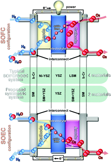 | ||
| Fig. 1 Scheme of traditional SOFC and SOEC systems and the proposed new configuration (b-Cr: chromium-based interconnect can be a perovskite material or a metallic interconnect; SM: symmetrical electrode material). | ||
This type of configuration is not new to fuel cell technology, indeed, Polymeric Fuel Cells (PEMFC) can use “symmetrical electrodes” made of fine dispersion of catalyst nanoparticles, e.g.Pt, over a carbon-based current collector. Hence, one may also find a similar system for high temperature fuel cells.
The development of SSOFCs simplifies notably the production of fuel cells, because the assembly of the electrolyte and the symmetrical electrodes can be performed in just one thermal step, hence decreasing the fabrication costs derived from the simpler fabrication process. Additionally, the use of the same material as anode and cathode will also minimise compatibility problems because two identical electrode–electrolyte interfaces are used in comparison with the typical anode–electrolyte and cathode–electrolyte interfaces in traditional SOFCs.
One of the most important advantages associated with the use of SSOFCs will be the possibility to address problems related to sulphur poisoning and carbon deposition by simply reversing the gas flows. In addition, if the selected materials are able to withstand variable redox conditions, then the materials can be also considered as potential SOEC electrode candidates.
This alternative concept, where the same electrode material is used, simultaneously, as cathode and anode in a SOFC, replacing the traditional configuration, was proposed in 2006 by both Irvine and co-workers3 and Ruiz-Morales et al.4
Such a SOFC concept rendered maximum performances of ∼550 and ∼350 mW cm−2, at 950 °C using pure H2 and CH4 as fuel, respectively, and O2 as oxidant.4 The redox-stable electrode chosen in both studies was the perovskite La0.75Sr0.25Cr0.5Mn0.5O3¬δ (LSCM), and the preliminary studies performed by the St Andrews group on this material working as a symmetrical reversible SOFC, e.g. a symmetrical SOEC, Fig. 2, rendered an area specific resistance of 0.84 Ω cm2 in electrolyser mode.3
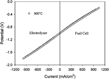 | ||
| Fig. 2 Current–voltage curve of the symmetrical cell LSCM/YSZ/LSCM under fuel cell and electrolyser modes in wet H2versus wet O2.3 | ||
In the work presented herein, we summarise the materials tested as symmetrical electrodes, comparing the performance obtained (Table 1), the electrochemical behaviour in oxidising and reducing conditions (Table 2), their potential use for SOECs and the strategies followed to enhance the performance of SSOFCs.
| System | Fuel: H2 | Fuel: CH4 | T/°C | Electrolyte | t (μm) | Ref. | ||
|---|---|---|---|---|---|---|---|---|
| P (mW cm−2) | OCV (V) | P (mW cm−2) | OCV (V) | |||||
| a P: Performance; t: electrolyte thickness. b City gas. c Dry fuel. d 5% H2. e Several μSOFC systems based on Pt (ref. 81 and references therein); LSCM: La0.75Sr0.25Cr0.5Mn0.5O3−δ. | ||||||||
| La0.7Ca0.3CrO3¬δ | 110 | 1.05 | 25 | 0.78 | 950 | YSZ | 2000 | 29 |
La0.7Ca0.3Cr0.97O3¬δ:YSZ (1![[thin space (1/6-em)]](https://www.rsc.org/images/entities/char_2009.gif) : :![[thin space (1/6-em)]](https://www.rsc.org/images/entities/char_2009.gif) 1) 1) |
92.1–27.5 | 1.06–1.10 | — | — | 850–750 | YSZ | 350 | 32 |
La0.7Ca0.3CrO3¬δ:CGO20 (1![[thin space (1/6-em)]](https://www.rsc.org/images/entities/char_2009.gif) : :![[thin space (1/6-em)]](https://www.rsc.org/images/entities/char_2009.gif) 1) 1) |
573–205 | 1.06–0.97 | 333b | 0.93 | 900–800 | LSGM | 300 | 33 |
LSCM:YSZ (1![[thin space (1/6-em)]](https://www.rsc.org/images/entities/char_2009.gif) : :![[thin space (1/6-em)]](https://www.rsc.org/images/entities/char_2009.gif) 1) 1) |
546 | 1.08 | 347 | 0.92 | 950 | YSZ | 250 | 4 |
LSCM:YSZ (7![[thin space (1/6-em)]](https://www.rsc.org/images/entities/char_2009.gif) : :![[thin space (1/6-em)]](https://www.rsc.org/images/entities/char_2009.gif) 3) + 2 layers of (La0.75Sr0.25)0.9Cr0.5Mn0.5O3¬δ 3) + 2 layers of (La0.75Sr0.25)0.9Cr0.5Mn0.5O3¬δ |
300 | 1.00 | 230 | 0.95 | 900 | YSZ | 200 | 3 |
LSCM:YSZ (1![[thin space (1/6-em)]](https://www.rsc.org/images/entities/char_2009.gif) : :![[thin space (1/6-em)]](https://www.rsc.org/images/entities/char_2009.gif) 1) 1) |
246–75 | 1.01–1.05 | — | — | 850–700 | YSZ | 1000 | 42 |
LSCM:CGO:YSZ (2![[thin space (1/6-em)]](https://www.rsc.org/images/entities/char_2009.gif) : :![[thin space (1/6-em)]](https://www.rsc.org/images/entities/char_2009.gif) 1 1![[thin space (1/6-em)]](https://www.rsc.org/images/entities/char_2009.gif) : :![[thin space (1/6-em)]](https://www.rsc.org/images/entities/char_2009.gif) 1) 1) |
400 | 1.01 | 125 | 0.87 | 950 | YSZ | 180 | 44 |
| LSCM:YSZ (63 wt% YSZ) | 333–87c | 1.06–1.11 | 265–36c | 1.05–0.84 | 900–700 | YSZ | 20 | 45 |
| LSCM:YSZ (63 wt% YSZ) + 5 wt% CSO | 395–93c | — | 298–61c | — | 900–700 | YSZ | 20 | 45 |
| LSCM:YSZ (63 wt%YSZ) + 6 wt% Ni | 570–105c | 1.05–1.10 | 550–115c | 1.11–0.95 | 900–700 | YSZ | 20 | 45 |
| Pr0.7Ca0.3Cr0.6Mn0.4O3¬δ | 250 | 1.09 | 160 | 0.95 | 950 | YSZ | 370 | 50 |
| La0.75Sr0.25Cr0.5Fe0.5O3¬δ | 35c | 0.95 | — | — | 800 | LSGM | 1500 | 56 |
| La0.75Sr0.25Cr0.5Al0.5O3¬δ | 45c | 0.92 | — | — | 800 | LSGM | 1500 | 56 |
La4Sr8Ti7Fe5O38−δ + 2 layers 1![[thin space (1/6-em)]](https://www.rsc.org/images/entities/char_2009.gif) : :![[thin space (1/6-em)]](https://www.rsc.org/images/entities/char_2009.gif) 1 with YSZ & 1 1 with YSZ & 1![[thin space (1/6-em)]](https://www.rsc.org/images/entities/char_2009.gif) : :![[thin space (1/6-em)]](https://www.rsc.org/images/entities/char_2009.gif) 1 with CeO2 1 with CeO2 |
87 | 1.04 | 31 | 1.01 | 950 | YSZ | 1000 | 65 |
| Sr2Fe1.5Mo0.5O6−δ | 835–645 | 1.07–1.05 | 230–100 | 0.90–0.82 | 900–850 | LSGM | 265 | 71 |
Pt-(YSZ-CeO2) (1![[thin space (1/6-em)]](https://www.rsc.org/images/entities/char_2009.gif) : :![[thin space (1/6-em)]](https://www.rsc.org/images/entities/char_2009.gif) 1) 1) |
140 | 1.09 | 40 | 0.99 | 950 | YSZ | 1210 | 74 |
| Pt e | 667–0.02 | 1.10–0.28 | — | — | 500–350 | YSZ | 0.75–0.05 | 81 |
| Pt | 1037cd | 0.968 | — | — | 500 | YSZ | 0.08 | 83 |
| Pt | — | — | 98cd | 0.84 | 440 | YSZ | 0.08 | 83 |
| La0.8Sr0.2Sc0.2Mn0.8O3¬δ | 310–220 | 0.99–1.02 | 130–100 | ∼0.81 | 900–850 | ScSZ | 300 | 84 |
| La0.6Sr0.4Co0.8Fe0.2O3 | 0.210c | 0.18 | 545 | YSZ | 0.06 | 86 | ||
| System | T/°C | σ air (S cm−1) | σ H2 (S cm−1)a | Electrolyte | R p air (Ω cm2) | R p H2 (Ω cm2) | Ref. |
|---|---|---|---|---|---|---|---|
| a Should be considered a rough estimation because parameters such as density, microstructure and oxygen partial pressure are not standardized (ref. 6). b 0.18 Ω cm2 under −400 mA cm−2. c 0.26–0.67 Ω cm2 under wet methane. d Wet 5% H2. e Obtained at 800 °C. f Wet methane. | |||||||
| LSCM | 900 | 38 | 3 | YSZ | 0.35 | 0.20 | 3,36 |
| LSCM-YSZ | 900 | — | — | YSZ | 0.29 | 0.59 | 42 |
| LSCM-YSZ | 950–850 | — | — | YSZ | 0.09–0.27 | 0.18–0.34c | 4 |
| La0.75Sr0.25Cr0.5Al0.5O3¬δ | 950–800 | — | — | LSGM | 0.18–1.2 | 0.3–0.45d | 46 |
| La0.75Sr0.25Cr0.5Mn0.3Ni0.2O3¬δ | 800 | 20 | 0.5 | YSZ | 1.6 | 1 | 54,55 |
| LaCrO3¬δ | 800 | 0.96 | 0.26 | — | — | — | 27 |
| La0.7Ca0.3CrO3¬δ | 800 | 50.1 | 1.6 | — | — | — | 27 |
La0.7Ca0.3Cr0.97O3¬δ:YSZ (1![[thin space (1/6-em)]](https://www.rsc.org/images/entities/char_2009.gif) : :![[thin space (1/6-em)]](https://www.rsc.org/images/entities/char_2009.gif) 1) 1) |
850 | 62 | 3.6 | YSZ | 0.16 | ∼2 | 32 |
La0.7Ca0.3CrO3¬δ:CGO20 (1![[thin space (1/6-em)]](https://www.rsc.org/images/entities/char_2009.gif) : :![[thin space (1/6-em)]](https://www.rsc.org/images/entities/char_2009.gif) 1) 1) |
850 | 18.6 | ∼1.9 | LSGM | — | — | 33 |
| La0.7Ca0.3Cr0.5Mn0.5O3¬δ | 800 | 29.9 | — | YSZ | 0.25 | 1.4e | 48 |
| Pr0.7Ca0.3Cr1-xMnxO3¬δ | 950–800 | 10 | 1–0.7 | YSZ | 0.7–4.0 | 5–40 | 50 |
| La1/3Sr2/3(Ti1-xFex)O3±δ | 950 | 0.9 | 0.1 | YSZ | 0.6 | 3 | 65 |
| Sr2Fe1.5Mo0.5O6−δ | 780 | 550 | 310 | LSGM | 0.24 | 0.27 | 71 |
| Pt-YSZ | 950 | — | — | YSZ | 0.20 | ∼60d | 74 |
Pt-(YSZ-CeO2) (1![[thin space (1/6-em)]](https://www.rsc.org/images/entities/char_2009.gif) : :![[thin space (1/6-em)]](https://www.rsc.org/images/entities/char_2009.gif) 1) 1) |
950 | — | — | YSZ | 0.05 | 0.45d | 74 |
| La0.8Sr0.2Sc0.2Mn0.8O3 | 850 | 45 | 6 | ScSZ | 6.5b | 0.35f | 84 |
Requirements for symmetric materials
The requirements for a material to be considered as a SOFC symmetrical electrode are rather restrictive as they should include all the conditions applicable to an anode and a cathode simultaneously.1 Furthermore, due to the variable redox atmosphere, additional requirements are imposed:5- The material should exhibit acceptable electronic conductivity in both oxidising and reducing conditions. A minimum value of 1 S cm−1 has been suggested.6 However, a value as low as 0.01 S cm−1 may be enough if the functional layer is thin enough.7
- It must be electrocatalytically active towards oxygen reduction and fuel oxidation, including hydrocarbons to avoid the use of external reformers.
- It should be structurally stable in both atmospheres, and chemically and physically compatible with the other fuel cell components. This implies that no reactions should occur between electrode and electrolyte during the cell assembly and in operating conditions.
- The differences between the Thermal Expansion Coefficients (TEC) should be negligible in a wide range of oxygen partial pressures to avoid delamination and cracks in the different layers.
Electrolyte choice
The electrolyte used in a symmetrical cell should fulfil the same requirements as that of traditional SOFCs. Therefore, apart from YSZ, some other alternative electrolytes8–10 with higher ionic conductivity than that of YSZ can be employed such as: La0.9Sr0.1Ga0.8Mg0.2O2.85 (LSGM),11 and apatite-type silicates12–15 for the intermediate temperature range (600 < T < 800 °C) and ceria16,17 and La2Mo2O9-based electrolytes18–20 for the low temperature range (T < 600 °C).Proton conductors can also be used as solid electrolytes and especially barium cerates and zirconates with higher conductivity values than ceria at low temperatures <600 °C.21–25
The use of mixed ionic–electronic conductors (MIECs) as electrolytes, with volume changes in variable atmospheres, is not recommended. This type of change may lead to the degradation of the symmetrical cell after a few redox cycles. In this sense the use of ceria-based materials should be restricted to very low temperatures (<600 °C) to minimise this effect and mainly as a component of the symmetrical electrode. An approach to overcome this drawback is to deposit a thin and dense layer of YSZ on the CGO electrolyte to prevent ceria reduction, however the different thermal expansion coefficients of CGO and YSZ might produce cracks and delaminations between both materials. Furthermore, the number of layers and interfaces of the symmetrical cells would increase, which complicates the fuel cell design and processing.
Symmetric materials obtained from SOFC interconnect materials
The chromites, traditionally used as interconnect materials,1 fulfil most of the conditions required for a symmetrical electrode. Basically, the electronic conductivity under oxidising conditions is high, but poor under reducing conditions. Some doped samples, especially those containing Ca, show very low TEC mismatches in a wide range of oxygen partial pressures.26 Jiang et al.27 found that Sr- and Ca-doped LaCrO3 perovskites exhibit high electrical conductivities, especially in air. The main problem is related to their modest catalytic activity towards hydrocarbon oxidation,28 although this may help to avoid the problem of carbon deposition, which is interesting considering operation in the long term.Ca-substituted lanthanum chromites
Early studies on this type of materials in 2007,29 with a Ca-substituted lanthanum chromite, La0.7Ca0.3CrO3¬δ (LCC), revealed promising electrochemical performance under pure hydrogen of approximately 110 mW cm−2 and overall polarisation resistance of 0.80 Ω cm2 at 950 °C with a thick YSZ electrolyte. As expected, the performance under methane was rather modest, i.e. 25 mW cm−2 at 950 °C, due to several factors, such as the poor catalytic activity of simple chromites towards hydrocarbon oxidation,28 a poor microstructural optimisation of the electrode and the thick electrolyte layer of 2 mm.NASA later on, in 2007,30 used the same materials YSZ and LCC for the fabrication of a symmetrical planar SOFC model aiming for devices with higher specific power densities. They used a new freeze tape-casting procedure to tailor the porosity of a symmetrical YSZ backbone, Fig. 3. The porous layer is used to support a thin LCC interconnect (30–60 μm) and the whole sample is sintered in one thermal step.
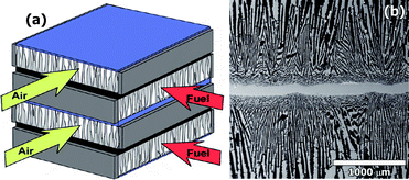 | ||
| Fig. 3 (a) NASA bi-supported cell (BSC) cross-flow stack. (b) Cross-section of sintered BSC before infiltration processes. Reproduced from ref. 30 with permission. | ||
The porous layers were impregnated with Ni-based nitrates for the anode side and Sr-doped LaFeO3 nitrates for the cathode side.31 However, this design has the potential to become a very interesting system if instead of being impregnated with Ni and LaFeO3 nitrates, both sides are impregnated with LCC nitrates, producing a symmetric system SSOFC totally compatible with the interconnect material.
Lin et al.,32 in 2010, synthesised a chromium deficient material, La0.7Ca0.3Cr0.97O3¬δ (LCC97), which exhibits much higher conductivity (e.g. 50.1 S cm−1 in air and 1.6 S cm−1 in H2 at 800 °C) compared with the stoichiometric LCC compound (e.g. 0.96 and 0.26 S cm−1 in air and H2 at 800 °C respectively).27 The performance obtained at 850 °C, under H2, was 92.1 mW cm−2, using a YSZ:LCC97 1![[thin space (1/6-em)]](https://www.rsc.org/images/entities/char_2009.gif) :
:![[thin space (1/6-em)]](https://www.rsc.org/images/entities/char_2009.gif) 1 composite as symmetrical electrode and a 350 μm YSZ electrolyte layer. The overall polarization resistance (anode + cathode) ranges from 4.20 Ω cm2 at 650 °C to 0.16 Ω cm2 at 850 °C.
1 composite as symmetrical electrode and a 350 μm YSZ electrolyte layer. The overall polarization resistance (anode + cathode) ranges from 4.20 Ω cm2 at 650 °C to 0.16 Ω cm2 at 850 °C.
The introduction of a MIEC improves notably the response of the symmetric electrodes as shown by Zhang et al.33,34 Indeed, these authors used LCC and a Ce1−xGdxO2−δ (x = 0.2, 0.3 and 0.4) composite in a systematic study to evaluate the effect of the ceria content in the symmetric electrode responses. The best electrical conductivities of 18.64 S cm−1 in air and 1.86 S cm−1 in H2 at 850 °C are achieved for a composite of 80 wt% LCC–20 wt% Ce0.8Gd0.2O1.9. The performances obtained in a fuel cell were 387 and 573 mW cm−2, at 850 and 900 °C respectively, under dry H2 using a 300 μm layer of LSGM as electrolyte.
Further performance improvements can be achieved if the MIEC is introduced into the electrode microstructure through impregnation processes. Zhang et al.34 reported a fabrication process involving five impregnation cycles of LCC by a precursor solution of Ce0.9Gd0.1O1.95 (CGO10) and a final firing step at 850 °C for 30 min, Fig. 4. This nanostructured system rendered maximum power densities of 638 mW cm2 at 900 °C under H2.
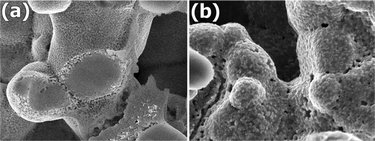 | ||
| Fig. 4 SEM images corresponding to the microstructure of LCC impregnated with CGO 5 times. (a) As prepared after calcination at 850 °C for 30 min and (b) after cell testing at 800 °C for 11 h. Reproduced from ref. 34 with permission. | ||
The same authors33 have also investigated the potential use of symmetrical electrodes in cells fuelled with city gas (59.6% H2, 22.1% CH4, 9.3% CO and 3.4% N2) containing ammonia and H2S as impurities (∼12 ppm and 5 ppm, respectively), Fig. 5. Although longer term tests would be very relevant, preliminary results in LCC-CGO20 based symmetrical cells delivered 330 mW cm−2 at 900 °C. The introduction of CGO by impregnation improved the performance to 491 mW cm2 under identical experimental conditions.34
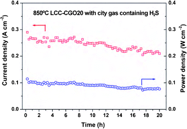 | ||
| Fig. 5 Electrochemical stability test curve for LCC-CGO20/LSGM/LCC-CGO20 symmetrical cell using humidified commercial city gas (containing H2S) as fuel and ambient air as oxidant at 850 °C. Reproduced from ref. 33 with permission. | ||
Consequently, LCC materials can be considered as promising symmetrical electrodes, although long term tests are needed to clarify any possible degradation of these materials due to the formation of volatile hydroxyl species as predicted by Sfeir.35
Symmetric materials obtained from SOFC anode materials
The anode materials commonly used in SOFCs exhibit high electronic conductivity under reducing conditions and good catalytic activity towards hydrogen and hydrocarbon oxidation. Generally, they are synthesized under oxidising atmospheres, but operate under reducing conditions, and hence the main concern in the present case is to know whether the selected material will also have high electronic conductivity under oxidising conditions, and catalytic activity towards oxygen reduction.Lanthanum chromium manganites
The substitution of Cr for Mn in LaCrO3 was initially suggested by Sfeir et al.28 as a way to improve the lack of catalytic activity of non-substituted chromites towards hydrocarbon oxidation and to increase their stability in reducing conditions.35The composition La0.75Sr0.25Cr0.5Mn0.5O3¬δ (LSCM) was reported by Tao and Irvine36,37 as a good alternative anode material to the traditional Ni-YSZ cermet. The A-deficient composition (La0.75Sr0.25)0.95Cr0.5Mn0.5O3¬δ (LSCM95) has also been proposed as a cathode material for SOEC under feeding gas with low concentration of H2 or even steam without H2.38
Nevertheless, chromites and manganites have been generally considered as air electrode materials and therefore LSCM was chosen as the first material tested in the proof of the concept in SSOFCs.
In oxidizing atmospheres, this perovskite exhibits a predominant p-type electronic conductivity, which lies in the range 20–35 S cm−1, whilst under reducing conditions the conductivity is relatively low, <5 S cm−1. Hence, LSCM exhibits larger conductivity in air than in hydrogen and it was initially the main reason to test this material as a cathode for SOFCs.
The polarization resistances for LSCM with YSZ electrolyte, obtained under symmetrical atmospheres in a two electrode configuration and open circuit were: 0.35 and 0.2 Ω cm2 at 800 °C in air and 5% H2–Ar respectively.3,36 It should be commented that the values of polarization resistance, obtained in symmetrical half cell configuration, are usually higher than those obtained under fuel cell configuration, when a direct current is applied across the cell. In addition, the polarization resistance in air is improved when a LSCM-YSZ composite is used: 0.29 Ω cm2.42
LSCM-based symmetric cells exhibited performances as high as 300 and 230 mW cm−2 at 900 °C, under humidified pure hydrogen and methane, respectively,3 using a 200 μm thin YSZ layer as electrolyte. The symmetrical electrode was assembled as a single layer of a LSCM:YSZ composite in a 7![[thin space (1/6-em)]](https://www.rsc.org/images/entities/char_2009.gif) :
:![[thin space (1/6-em)]](https://www.rsc.org/images/entities/char_2009.gif) 3 ratio and two additional layers of pure LSCM acting mainly as current collectors.
3 ratio and two additional layers of pure LSCM acting mainly as current collectors.
The optimisation of the LSCM microstructure, using polymethyl methacrylate (PMMA) microspheres as pore formers, Fig. 6, was applied to overcome the problems of the poor microstructure previously observed in chromites.39–41 Such an approach allows better control of the porosity and produces better values of the polarisation resistances, especially working with hydrocarbon fuels. Power density values of 500 and 300 mW cm−2 at 950 °C, under humidified pure hydrogen and methane respectively, were obtained.4
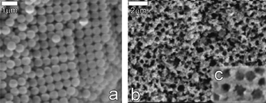 | ||
| Fig. 6 SEM pictures of (a) PMMA microspheres used to control the porosity in the LSCM-YSZ composite; (b,c) optimised microstructure of a LSCM-YSZ composite after removal of organic template.4 | ||
Jiang et al.42 prepared a composite of LSCM-YSZ using a gel-casting procedure. This approach allows reduction of the sintering temperature by 50–100 °C compared to the traditional solid-state reaction. The composite prepared at 1100 °C exhibits the better overall electrocatalytic activity, rendering performances of 275 mW cm−2 at 850 °C under H2 with a 1 mm thick YSZ layer as electrolyte.
However, it should be mentioned that the main drawback of LSCM for practical applications is the low electronic conductivity under reducing conditions. This has been clearly revealed by Kharton et al.43 through the study of the electrochemical behaviour of LSCM95 in a broad range of oxygen partial pressures from 10−20 to 0.5 atm. This study shows that under reducing conditions the electronic conductivity decreases to 1–3 S cm−1 although there is an important increase in the oxygen vacancy concentration and consequently the ionic conductivity is enhanced. As the authors pointed out, the addition of an electronically conductive material and/or a highly dispersed catalyst can significantly improve the electrode performance.43 In other words, the use of LSCM as symmetric electrode is conditional on the use of an adequate current collector or depositing the electrode material as a very thin layer as suggested by Gross et al.7
As described in the previous section, the electrochemical response of the electrode materials can be enhanced through the use of a MIEC, such as gadolinium-doped ceria (CGO) to fabricate composites with LSCM. A 2![[thin space (1/6-em)]](https://www.rsc.org/images/entities/char_2009.gif) :
:![[thin space (1/6-em)]](https://www.rsc.org/images/entities/char_2009.gif) 1
1![[thin space (1/6-em)]](https://www.rsc.org/images/entities/char_2009.gif) :
:![[thin space (1/6-em)]](https://www.rsc.org/images/entities/char_2009.gif) 1 (w/w) composite of LSCM-CGO-YSZ showed an enhancement of the polarisation resistances of at least a factor of 2 compared to YSZ-based composites with polarisation resistance values at open circuit of 1 Ω cm2 in air and 2 Ω cm2 in wet 5% H2–Ar, Fig. 7. Furthermore, the series resistances were also improved due to an increase of the CGO electronic conductivity in reducing conditions. The (LSCM-CGO-YSZ)-based fuel cells rendered power density values of 400 and 125 mW cm−2 at 950 °C with humidified pure hydrogen and methane respectively.44
1 (w/w) composite of LSCM-CGO-YSZ showed an enhancement of the polarisation resistances of at least a factor of 2 compared to YSZ-based composites with polarisation resistance values at open circuit of 1 Ω cm2 in air and 2 Ω cm2 in wet 5% H2–Ar, Fig. 7. Furthermore, the series resistances were also improved due to an increase of the CGO electronic conductivity in reducing conditions. The (LSCM-CGO-YSZ)-based fuel cells rendered power density values of 400 and 125 mW cm−2 at 950 °C with humidified pure hydrogen and methane respectively.44
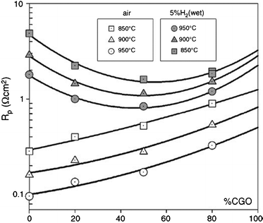 | ||
| Fig. 7 Dependence of the polarisation resistances on the CGO content, under 5% H2 and air, in the LSCM-YSZ-CGO mixed composite.44 | ||
The impregnation of electrode precursor solutions has been also used to enhance the performance of LSCM. Kim et al.45 have prepared LCM electrodes impregnated into porous YSZ scaffolds. Those anodes were prepared by aqueous infiltration of nitrate salts to produce 45 wt% of La0.75Sr0.25Cr0.5Mn0.5O3 (LSCM) in a 65% porous yttria-stabilized zirconia (YSZ) scaffold. This impregnation method gave rise to high performance SOFC anodes able to operate on humidified hydrogen and methane gases. A similar approach was used to prepare symmetrical SOFCs with LSCM. Zhu et al.46 used an alternative dry-pressing procedure to fabricate, in a single step, a dense thin layer (20 μm electrolyte) sandwiched between porous layers of YSZ, Fig. 8. The porosity is created by using NiO, which is chemically removed in a further stage, following a procedure previously described by Kim et al.47 After that the symmetrical electrode, LSCM, is incorporated by impregnation with nitrate precursors, and finally the whole assembly is fired at 1100 °C for 2 h, the final content of LSCM being 32 wt.%.
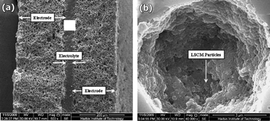 | ||
| Fig. 8 (a) SEM micrograph showing a cross sectional view of the sintered SOFCs with two symmetric NiO/YSZ electrodes after reduction and further acid cleaning. (b) SEM image of the resulting electrode after impregnation with LSCM. Reproduced from ref. 45 with permission. | ||
Such cells rendered power density values between 87 and 333 mW cm−2, in the temperature range 700–900 °C, in dry H2. The performance drops to 36–265 mW cm−2 when the cell is fuelled with dry methane in the same temperature range. These values can be further enhanced through the incorporation of a ceria-based precursor during the impregnation process, Fig. 8. In this case, the addition of 5 wt.% samaria-doped ceria (CSO) renders maximum power density values, Table 1, of 395 and 298 mW cm−2 at 900 °C under H2 and CH4 respectively.45
The most surprising result is obtained when a Ni-based precursor is also used in the impregnation solutions. In this case, the addition of 6 wt.% Ni boosts the overall performance of the symmetrical system by a factor of two compared to the Ni-free symmetrical electrodes,45i.e. 570 and 550 mW cm−2 for dry H2 and CH4. It is worth noting that the maximum power densities are rather similar under both H2 and methane and the same behaviour is observed in the OCV values under CH4, ranging between 1.05 and 1.10 V, Fig. 9, which may be related to the optimisation of the electrode microstructure. The lack of electronic conductivity and catalytic activity in oxidising conditions from the NiO seems to be greatly compensated with both these two factors under reducing conditions even when used in low concentrations. The main drawback is the detrimental microstructural effect expected from the volume change of Ni when switching between oxidising and reducing atmospheres. For this reason, a low concentration of Ni seems to be crucial to minimise this negative issue.
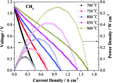 | ||
| Fig. 9 Voltage–current density and performance curves of a SSOFC with 6 wt.% Ni impregnated LSCM material, operating at 700–900 °C in dry CH4. Reproduced from ref. 45 with permission. | ||
A-site modified chromium manganites
The effect of the substitution of the elements in the A-site of the perovskite LSCM has been the subject of several works.48–51Zhang et al.48 studied the effect of the Ca and Ba in the system La0.7A0.3Cr0.5Mn0.5O3¬δ (A = Ca, Sr and Ba). The authors found that Ca-doping (LCCM) produces the best electrochemical activity. The LCCM system reached conductivity values of 29.9 S cm−1 at 800 °C in air. The electrocatalytic cathode response was greatly improved by CGO impregnations (6.02 mg cm−2) down to 0.4 Ω cm2 compared with 24.4 Ω cm2 without impregnation, Fig. 10. Also the authors proved that LCCM exhibits much better electrocatalytic activity in reducing conditions than the corresponding system with Ba or Sr, with polarisation resistances under H2 of 1.4, 2.1 and 11.1 Ω cm2, for LCCM, LSCM and LBCM respectively at 800 °C. The poorer results of the latter seem to be related to segregation of barium at the grain boundaries and the formation of BaCrO4.
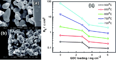 | ||
| Fig. 10 Cross-section SEM micrographs of (a) pure LCCM electrode, (b) 6.02 mg cm−2 CGO-impregnated LCCM electrode after the cell testing. (c) Plots of the electrode polarization resistance for the oxygen reduction reaction on LCCM electrodes as a function of impregnated CGO loading. Reproduced from ref. 48 with permission. | ||
In 2005, Liu et al.49 synthesised a new interconnect material Pr0.7Ca0.3Cr0.98O3 (PCC98), which avoids the typical structural transformation of LaCrO3-based materials at high temperature. In addition, PCC98 shows an average thermal expansion coefficient (TEC) of 10.8 × 10⁻⁶ K−1 compatible with YSZ, and exhibits modest electronic conductivity in reducing conditions, e.g. 1.08 S cm−1 at 800 °C. Hence, a symmetrical system based on PCC98 may be an interesting candidate material for SSOFCs.
El-Himri et al.50 studied a new series of compound based on Pr0.7Ca0.3Cr1−yMnyO3¬δ (y = 0.2–0.8) prepared via a freeze-drying process to avoid the formation of secondary phases that generally occurs when using the traditional solid-state reaction route. The compounds crystallise in the orthorhombic system and were chemically compatible with YSZ (at least up to 1200 °C). The electrochemical studies showed an improvement of the electrochemical response with increasing the Mn content with conductivity values of 8 and 0.4 S cm−1 in air and 5% H2–Ar at 800 °C for the composition y = 0.4. For the same composition and temperature the polarisation resistances at open circuit were: 4 Ω cm2 in air and 40 Ω cm2 in 5% H2–Ar .
However, high temperature studies during specimen annealing showed that samples with Mn content higher than 0.6 are unstable under 5% H2 atmosphere, in full agreement with the results published by Raj et al.51 They found that the Pr substitution decreases the Mn oxidation state making it more likely to decompose under reduction conditions. Hence, the performances were obtained with the sample containing the minimum composition of Mn (y = 0.4) that seems to be stable under reducing conditions and reached modest values of power densities 250 and 160 mW cm−2 at 950 °C, under humidified H2 and CH4 respectively.
Recently, the possibility to introduce new electrochemical properties in LSCM by replacing lanthanum in the A-site of the perovskite by cerium has been tested by Lay et al.52 The materials were prepared in mildly reducing conditions, under Ar, forming the series of compounds CexLa1−xSr0.25Cr0.5Mn0.5O3 (x = 0–0.375). The materials are stable in SOFC wet reducing conditions and in steam electrolysis SOEC cathodic conditions. The increase of cerium content enables the improvement of the electronic conductivity up to 35 S cm−1 under humidified pure H2 and 1.2 S cm−1 under humidified Ar at 900 °C. Unfortunately, the materials readily decompose leading to the formation of cerium oxide under oxidising conditions or in dry fuels, and hence the applicability as a symmetrical electrode is not feasible.
B-site modified chromium manganites
Kolotygin et al.53 proposed the introduction of Ti4+ into the B-site of the LSCM perovskite in combination with an increase of the Sr2+ content in the A-site. The main aim was to avoid problems related with the possible evaporation of Cr species. The results indicate that the system (La0.75−xSr0.25+x)0.95Mn0.5Cr0.5−xTixO3¬δ (x = 0–0.5) exhibits p-type electronic conductivity, in oxidising and mild reducing conditions. The authors indicated that it is possible to totally suppress the Cr content without compromising the behaviour as a cathode material. The electrochemical response in these conditions is strongly dependent on the nature of the electrolyte, as the response with LSGM is much better than with the apatite-type La10Si5AlO26.5 electrolyte, e.g. the cathodic overpotential can be three times higher compared to that of the LSGM. Unfortunately, under H2 atmosphere the response becomes poor and it may be necessary to incorporate an additional element such as a ceria-based material to improve the response as an anode.Another option tested by Jardiel et al.54 was to introduce Ni into the B-site of LSCM, replacing part of the Cr and Mn. The limit of the Ni solid solution is 20%. The conductivities of the material are high in both oxidising and reducing conditions. Another important feature of the (La0.75Sr0.25)(Cr0.5Mn0.3Ni0.2)O3¬δ compound is its selectivity toward the total hydrocarbon oxidation being a better candidate than LSCM. Polarisation values of 1.6 and 1 Ω cm2 were reported by Delahaye et al.,55 under air and humidified wet 5% H2 respectively, at 800 °C in symmetrical cells.
The Mn content in LSCM has also been totally replaced by other elements such as Fe and Al. Peña-Martínez et al.56 tested several potential symmetrical materials La0.75Sr0.25Cr0.5X0.5O3¬δ, X = Mn, Fe and Al, (LSCrM, LSCrF and LSCrA) with LSGM electrolyte. The study showed that the fabrication temperature of the cell components is crucial to avoid undesired reactions with the electrolyte, i.e.LSCrF strongly reacts with LSGM above 900 °C. The best results in terms of power densities follow the trend Mn > Al >Fe, Fig. 11.
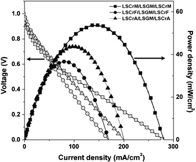 | ||
| Fig. 11 Voltage–current density and power density curves of the symmetric systems of LSCrM, LSCrF and LSCrA at 800 °C using wet 5% H2–Ar as fuel and air as oxidant.56 | ||
Substituted strontium titanates
The strontium titanates typically tested as anode materials57,58 exhibit high electronic conductivities under reducing conditions and generally they can operate with sulphur-containing fuels.59,60 Furthermore, recently it has been shown that the introduction of different elements into the B-site of the perovskite, e.g. Sc,61Mn,62 and (Ga,Mn),63,64 seems to promote catalytic activity towards hydrocarbon oxidation. Hence, these materials are an attractive option if they can be converted into symmetrical SOFC electrodes.7The titanates show mainly n-type electronic conductivity in the whole pO2 range, thus, the strategy consists of replacing some Ti for another transition metal that could introduce p-type conductivity in oxidising conditions. One of the candidates proposed by Canales-Vázquez et al.65 was the system (La,Sr)(Ti1−xFex)O3±δ, with x ≤ 0.5. The combination of Ti and Fe results in the introduction of both n-type and p-type conductivity.66–69 The system is stable with time under both oxidising and reducing conditions. The best results are obtained for x = 0.5 in the La1/3Sr2/3(Ti1−xFex)O3±δ (LSTF) series with values of conductivity of 0.9 S cm−1 in air and 0.1 S cm−1 in 5% H2–Ar.65 The authors observed that the LSTF electrodes exhibit better performance in air than under reducing conditions. In addition, a notable improvement of the polarisation resistances with increasing Fe-content was observed under reducing conditions. Therefore, Fe substitution in these phases has a double benefit: the overall electronic conductivity increases and, more important, the catalytic activity of the electrodes improves notably. Polarisation resistance values of 3.0 and 0.6 Ω cm2 at 950 °C under 5% H2–Ar and air respectively were obtained for the symmetrical system LSTF/YSZ/LSFT, using a 1 mm thick YSZ electrolyte.65 The polarisation values were larger under methane, indicating a rather limited application of these composites in direct methane fuel cells.65 However, the fabrication of graded composites70 resulted in polarisation values improved by a factor of two. The performance in symmetric configuration, using a fine layer of Au as current collector, was 100 mW cm−2 under wet H2 at 950 °C, with stable OCV values of approximately 1.0 V under methane at 950 °C.
Novel perovskite Sr2Fe1.5Mo0.5O6−δ
Recently a new promising material has been proposed for SSOFCs and SSOECs by Liu et al.71–73 The composition Sr2Fe1.5Mo0.5O6−δ (SFM) exhibits very high electronic conductivities, i.e. 550 and 310 S cm−1 under air and hydrogen respectively at 780 °C.71 The authors tested the compatibility with several electrolytes, such as YSZ, LSGM, CSO and BZCY, up to 1400 °C for 24 h. Reactivity between SFM, CGO and BZCY was not observed; however reaction products were found between SFM and YSZ at 1000 °C.71The polarisation resistances at open circuit conditions for SMM obtained from symmetrical cells with LSGM electrolyte at 800 °C were: 0.24 and 0.27 Ω cm2 under air and H2, respectively. The power densities obtained in a SSOFC of SFM/LSGM/SFM, with a 265 μm layer of LSGM, were 835 and 230 mW cm−2, at 900 °C, under wet H2 and CH4, respectively.
As occurred for several other systems already described, the polarisation values can be further improved by impregnation with a MIEC such as CSO. This was proved by Zhang et al.72 that reported a decrease of a factor of two in the polarisation values of SFM, at 750 °C, using CSO nanoparticles.
A remarkable feature of this material is that it can be used as a symmetrical SOEC. Liu et al., in 2010,73 showed that, at 900 °C, and under 60% absolute humidity (AH), the SFM/LSGM/SFM polarisation resistance was just 0.26 Ω cm2. In the same conditions of humidity and temperature, and under 1.3 V electrolysis voltage, an electrolysis current of 0.88 A cm−2 and 380 ml cm−2 h H2 is produced, Fig. 12, these values being comparable to those of a typical SOEC system such as LSM-YSZ/YSZ/Ni-YSZ. This system has been tested under electrolysis operation for 90 h with no noticeable degradation, and is relatively stable at high temperature and high humidity environment. Thus, this system can be considered both a symmetric SOFC and a symmetric SOEC, and hence a SR-SOFC.
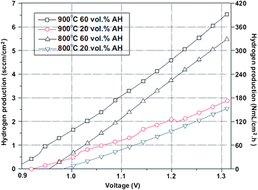 | ||
| Fig. 12 Hydrogen production of a single cell SFM/LSGM/SFM as a function of the absolute humidity and operating temperatures. Reproduced from ref. 73 with permission. | ||
Precious metal-based systems
The combination of YSZ plus a MIEC, used in many anode materials, and Pt, Au or Ag, typically considered as current collectors, despite their price, fulfils most of the requirements to be considered as a symmetric electrode material.The MIEC introduces catalytic activity towards oxidation and some additional electronic conductivity, whereas the ionic conductivity is mainly given by the YSZ. The precious metal provides electronic conductivity (and also catalytic contributions can be expected as occurs with Pt under hydrocarbon fed) in both environments and the combination of the three elements seems to enhance the catalytic properties under both oxidising and reducing conditions, e.g. the polarisation resistance under air can be improved by a factor of two, and by a factor of three under reducing conditions, depending on the YSZ:MIEC ratio.74
Preliminary tests performed on this simple combination with Pt-YSZ-CeO2/YSZ/Pt-YSZ-CeO2 showed performances of ∼140 mW cm−2 at 950 °C under humidified H2. The authors also pointed out that for thin electrolytes and flat configurations it is possible to obtain performances higher than 500 mW cm−2 for small systems.74
As an example of a small system one can consider the micro-Solid Oxide Fuel Cells (μ-SOFCs).75–83 In this type of configuration just two elements are used, a very thin electrolyte (typically YSZ) and a thin layer of a current collector material with good catalytic properties in both oxidising and reducing conditions, e.g.Pt. In this case, there is no chance of enlarging the Triple Phase Boundary (TPB) through the electrode material, the electrochemical active layer being just the interface in contact with the electrolyte; hence optimisation of the electrode microstructure is critical to improve the efficiency of these devices.
μSOFCs operate at very low temperatures, ∼300–500 °C, and hence the ohmic drop from the electrolyte should be minimised. For this reason, the thickness of the electrolyte layers should be in the 10–100 nm range. In this case, the traditional fabrication processes are no longer valid and other sophisticated techniques are typically employed for the deposition of the thin electrode and electrolyte layers, such as pulsed-laser deposition, magnetron sputtering, atomic layer deposition, etc.81
In μ-SOFC systems, performances from 0.02 to 667 mW cm−2 have been reported with nanometre YSZ membrane-based electrolyte, at low temperatures, 350–500 °C, Table 1.
Recently, Kerman et al.83 reported very high performances, i.e. 1037 mW cm−2, and OCVs of 0.968 V using 5% H2 as fuel with nanoporous Pt electrodes and a 80 nm YSZ layer, at 500 °C. Under CH4 the same system was able to reproduce 95 mW cm−2 at 440 °C. In all cases the Pt loading was restricted to a few μg cm−2.
The main disadvantage is related to the observed microstructural changes in the nanostructured materials with the higher temperatures and/or reducing conditions on the anode side, Fig. 13. This leads to a reduction of 50% of the initial performance just after 12 h of operation at 400 °C.83
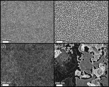 | ||
| Fig. 13 SEM micrographs of the cathode (a) and anode (b) as-deposited, and (c,d) after heating to 400 °C for 6 h. Reproduced from ref. 83 with permission. | ||
Symmetric materials obtained from SOFC cathode materials
The common cathode materials can be used to discover new potential symmetrical electrodes. Typically, the main problem to overcome is the low stability of such systems under reducing conditions, particularly lanthanum strontium manganites and cobalt ferrites are highly prone to decompose even under mild reducing conditions.1Lanthanum strontium manganites
In 2009, Zheng et al.84 reported a new symmetrical electrode based on a substituted lanthanum strontium manganite La0.8Sr0.2Sc0.2Mn0.8O3¬δ (LSSM). The introduction of scandium into the lanthanum manganite structure improves the stability under reducing conditions and produces better cathode performance. The stability under reducing conditions was attributed to the backbone effect of Sc3+ in the perovskite structure, hence allowing the reduction of Mn4+ to Mn3+ and not to Mn2+, which may lead to the decomposition of manganite-based materials. LSSM exhibits conductivities of 45 and 6 S cm−1 at 850 °C under air and 5% H2, respectively.The polarization resistance under air reached a value of 6.5 Ω cm2 at 850 °C when no direct current is applied and decreased to only 0.18 Ω cm2 after LSSM was subjected to 400 mA cm2 direct current. Such a significant improvement in electrode performance was attributed to the generation of oxygen vacancies, induced by the current polarization, at the electrode/electrolyte interface region by the partial reduction of Mn4+ to lower oxidation states. Polarisation resistance values under hydrogen were not reported in this work.
A 300 μm thick layer of a scandium-stabilised zirconia (ScSZ) was used as electrolyte for fuel cell testing. The performances obtained for the system LSSM/ScSZ/LSSM were 310 and 130 mW cm−2 at 900 °C under humidified hydrogen and methane respectively.
Lanthanum strontium ferrites
Our research groups have also tested another system based on common cathode materials, such as lanthanum strontium ferrites. Given that scandium seems to promote stability in reducing conditions,84,85 the new series studied was La0.6Sr0.4Fe1−xScxO3¬δ (x = 0.05–0.3). The best result was obtained for a Sc content of x = 0.1 prepared by solid state reaction at 1300 °C or by using the freeze-drying precursor at 1100 °C. The composition La0.6Sr0.4Fe0.9Sc0.1O3¬δ (LSFS) is stable in oxidising and reducing conditions, up to 900 °C with humidified 5% H2 and up to 850 °C with pure hydrogen. The conductivity under air reached maximum values of 105 S cm−1 at ∼550 °C. Measurements under symmetric atmospheres reported polarisation resistance values of 0.05, 0.45 and 0.24 Ω cm2, under oxygen, humidified 5% H2 and pure H2 respectively, at 950 °C using YSZ as electrolyte. In the temperature range of 950–850 °C, the polarisation resistance values were lower, ranging between 0.45 and 1.02 Ω cm2 under wet 5% H2: this seems to indicate that the use of LSFS probably must be restricted at high temperatures using either YSZ or LSGM electrolytes.This material was tested with CGO electrolytes in order to investigate the potential applicability of LSFS as an anode material, revealing very low polarisation resistances. Nevertheless, due to the electronic contribution of doped ceria at 600 °C, causing partial shortcircuiting, one should only consider the polarisation values obtained at lower temperatures. At this temperature a rather low value of ∼0.15 Ω cm2 was obtained under humidified pure hydrogen.
Lanthanum strontium cobalt-ferrites
Although perovskites based on cobalt ferrites are really sensitive to atmospheres with low oxygen partial pressures,1 a recent work on μ-SOFCs by Lai et al.86 reported the use of La0.6Sr0.4Co0.8Fe0.2O3−δ (LSCF) as a symmetrical electrode with a performance of 210 μW cm−2 at 545 °C with a very low OCV of 0.18 V. Although the performance can be considered modest, the most interesting feature is the stability of LSCF under reducing conditions. The authors suggested that the apparent stability is related to the thickness of the electrode material (nanometre range) and also to a very low operating temperature. An annealing 100 h test seems to confirm these assumptions.86Conclusions and prospective view
In this review an overview of the most relevant materials with potential applications in SSOFC electrodes has been presented. To date, LSCM has been the most studied system in several atmospheric conditions and temperatures, rendering performances of up to 650 and 500 mW cm−2 under humidified H2 and CH4 at relatively high temperatures (850–950 °C), Table 1.Nevertheless, there are several other compositions exhibiting rather promising properties, such as the case of Ca-substituted lanthanum chromites, because they allow replacing of the three elements (anode, cathode and interconnect) in a typical SOFC with the same symmetrical material. The performances are quite competitive under hydrogen at high temperatures and modest with hydrocarbon fuels though pretty stable especially under city gas with trace levels of H2S, which makes this material interesting from the commercial point of view.
In most of the analysed cases the use of MIECs, such as ceria-based nanoparticles, generally introduced by impregnation methods,87 allows enhancement of the overall SOFC performance. Further studies are required to determine the mechanisms that allow such a performance boost and also to define both the most adequate weight ratio and compositions.
The use of simple materials in combination, such as a cermet of a precious metal and an ionic or MIEC conductor, allows promising performances in typical SOFC configurations. However, they may reach higher performances through their integration in μ-SOFC systems. Performances in excess of 1 W cm−2 were reported at low temperatures (∼400 °C) using submicrometer-sized YSZ-based electrolytes.
The same combination of micro-systems and low operation temperature seems to promote the stability of SOFC cathode materials (e.g.cobalt ferrites), which are generally reported as unstable under mildly reducing conditions. These materials have been used as SSOFC electrodes, exhibiting good redox stability, although rather modest performances in the range of μW cm−2.
One of the most promising SSOFC systems seems to be the double perovskite Sr2Fe1.5Mo0.5O6 (SFM). This material exhibits conductivities higher than 300 S cm−1 in both oxidising and reducing conditions and performances in excess of 800 mW cm−2 at 900 °C with LSGM electrolyte. The most remarkable feature is its good functionality as a symmetrical electrode for SOEC. Hence, SFM can be considered a truly all-in-one Symmetrical and Reversible SOFC (SR-SOFC) material.
The integration of LSCM or SFM in μ-SOFCs may lead to new promising performances at very low temperatures, e.g. 300–350 °C. In these conditions, several polymeric materials can be used as flexible interconnect materials, flexible sealing agents, etc.
On the other hand, it is clear that engineering the electrode microstructure88–90 is critical to achieve performance enhancements as this may affect several parameters, such as the gas flow conduction paths, extension of the triple phase boundary (TPB), optimisation of the electrical and ionic networks inside the TPBs, mechanical stability, stability against redox changes, etc.
To date, all the fabrication processes described in the literature have been focused on flat configurations, typically using cost-effective approaches as screen printing, a novel freeze tape-casting procedure, dry pressing, colloidal crystal templating methods, etc., controlling the electrode porous structure. The development of alternative approaches to produce microtubular SSOFCs would be highly relevant as this configuration allows fast start-up, it may facilitate the interconnection between cells, the sealing is simpler and the mechanical stability is notably improved.91 To the best of our knowledge, this type of configuration has not been tested with SSOFCs materials although Zhang et al.92 tested an anode-supported hollow fiber SOFC (HF-SOFC), Fig. 14, using a LSCM-based cathode, e.g. (La0.75Sr0.25)0.95Cr0.5Mn0.5O3¬δ–Sm0.2Ce0.8O1.9–YSZ. Hence the use of the same combination LSCM-CSO-YSZ as SSOFC material for HF-SOFCs would be very interesting.
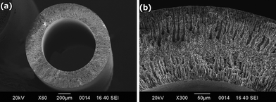 | ||
| Fig. 14 SEM images of an anode-supported hollow fiber SOFC. Reproduced from ref. 92 with permission. | ||
A new exciting approach for the production of structured materials on demand and assembly of SOFC components in one single step is the use of a 3D-printing system. Until the past few years, this type of technology has been restricted, for medium- and large-sized companies devoted to the fabrication of prototypes. Nowadays, they are increasingly available for small businesses, research and even for direct manufacturing.
Basically, a model of the object to be printed is created in a computer. The software indicates how many layers made of different cross-sections are necessary to print the full item depending on the resolution required. In the second step, each layer is printed on an appropriate substrate with a suitable ink. In conventional 2D printers this step is equivalent to printing each section on a different piece of paper. In 3D-printing, there are several options: one of them is to spread powder from a well, levelling it to produce a thin layer. Then the printer heads will dispense a thin layer of a binder in the required pattern of the cross-section. When the layer is finished, the "build tray" will be lowered by a fraction of a millimetre and then, the process is repeated again for the next cross-section. Finally, the loose powder is blown away with compressed air, revealing a complete structure.
Following this procedure, details can be reproduced below ∼20 μm. Improving the resolution to the range of 0.5–10 μm will allow the total control of the porosity of the assembled SOFC, and simulation studies related to the microstructure will be easily verified. Alternatively, the optimum electrode microstructure suggested by previous simulation studies will be fabricated within minutes.
Preliminary tests for the fabrication of simple mini-stack system have been successfully performed with a polymeric material, Fig. 15, and the implementation with ceramic powders, metals, glass, rubber, UV resins, etc. seems to be a straightforward task, opening new research engineering areas not restricted to the SOFC field.
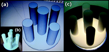 | ||
| Fig. 15 Fabrication of a prototype of a SOFC mini-stack of 5 cells using free software such as (a) Google SkechUp™ and with a laser-based 3D-printer and (b,c) functional layers of a polyamine. | ||
Acknowledgements
We would like to thank to Dr Neus Sabate and Dr J. P. Esquivel Bojorquez, from the National Microelectronic Center of Barcelona, for their assistance in the fabrication of structured 3D materials. This work was supported by the Spanish Research program MAT2010-19837-C06-04 and MAT2010-18743References
- N. Q. Minh and T. Takahashi, in Science and Technology of Ceramic Fuel Cells, Elsevier, Amsterdam, Netherlands, 1995 Search PubMed.
- A. Brisse, J. Schefold and M. Zahid, Int. J. Hydrogen Energy, 2008, 33, 5375 CrossRef CAS.
- D. M. Bastidas, S. Tao and J. T. S. Irvine, J. Mater. Chem., 2006, 16, 1603 RSC.
- J. C. Ruiz-Morales, J. Canales-Vázquez, J. Peña-Martínez, D. Marrero-López and P. Núñez, Electrochim. Acta, 2006, 52, 278 CrossRef CAS.
- J. C. Ruiz-Morales, J. Canales-Vázquez, H. Lincke, J. Peña-Martínez, D. Marrero-López, D. Pérez-Coll, J. T. S. Irvine and P. Núñez, Bol. Soc. Esp. Ceram. V., 2008, 47, 183 CrossRef CAS.
- A. Atkinson, S. Barnett, R. J. Gorte, J. T. S. Irvine, A. J. McEvoy, M. Moguensen, S. C. Singhal and J. Vohs, Nat. Mater., 2004, 3, 17 CrossRef CAS.
- M. D. Gross, J. M. Vohs and R. J. Gorte, Electrochem. Solid-State Lett., 2007, 10, B65 CrossRef CAS.
- A. J. Jacobson, Chem. Mater., 2010, 22, 660 CrossRef CAS.
- L. Malavasi, C. A. J. Fisher and M. S. Islam, Chem. Soc. Rev., 2010, 39, 4370 RSC.
- A. Orera and P. R. Slater, Chem. Mater., 2010, 22, 675 CrossRef CAS.
- T. Ishihara, H. Matsuda and Y. Takita, J. Am. Chem. Soc., 1994, 116, 3801 CrossRef CAS.
- S. Nakayama, T. Kageyama, H. Aono and Y. Sadaoka, J. Mater. Chem., 1995, 5, 1801 RSC.
- D. Marrero-López, M. C. Martín-Sedeño, J. Peña-Martínez, J. C. Ruiz-Morales, P. Núnez, M. A. G. Aranda and J. R. Ramos-Barrado, J. Power Sources, 2010, 195, 2496 CrossRef.
- J. E. H. Sansom, D. Richings and P. R. Slater, Solid State Ionics, 2001, 139, 205 CrossRef CAS.
- P. R. Slater, J. E. H. Sansom and J. R. Tolchard, Chem. Rec., 2004, 4, 373 CrossRef CAS.
- T. Kudo and H. Obayashi, J. Electrochem. Soc., 1976, 123, 415 CrossRef CAS.
- M. Mogensen, N. M. Sammes and G. A. Tompsett, Solid State Ionics, 2000, 129, 63 CrossRef CAS.
- P. Lacorre, F. Goutenoire, O. Bohnke, R. Retoux and Y. Laligant, Nature, 2000, 404, 856 CrossRef CAS.
- D. Marrero-López, J. Peña-Martínez, J. C. Ruiz-Morales, D. Pérez-Coll, M. C. Martín-Sedeño and P. Núñez, Solid State Ionics, 2007, 178, 1366 CrossRef.
- D. Marrero-López, J. Canales-Vázquez, J. C. Ruiz-Morales, J. T. S. Irvine and P. Núñez, Electrochim. Acta, 2005, 50, 4385 CrossRef.
- H. Iwahara, T. Yajima and H. Ushida, Solid State Ionics, 1994, 70–71, 267 CrossRef CAS.
- D. Shima and S. M. Haile, Solid State Ionics, 1997, 97, 443 CrossRef CAS.
- F. L. Chen, O. Toft Sørensen, G. Y. Meng and D. K. Peng, J. Eur. Ceram. Soc., 1998, 18, 1389 CrossRef CAS.
- N. Bonanos, B. Ellis, K. S. Knight and M. N. Mahmood, Solid State Ionics, 1989, 35, 179 CrossRef.
- E. Gorbova, V. Maragou, D. Medvedev, A. Demin and P. Tsiakaras, J. Power Sources, 2008, 181, 207 CrossRef CAS.
- W. Z. Zhu and S. C. Deevi, Mater. Sci. Eng., A, 2003, 348, 227 CrossRef CAS; J. W. Fergus, Solid State Ionics, 2004, 171, 1 CrossRef.
- S. P. Jiang, L. Liu, K. P. Ong, P. Wu, J. Li and J. Pu, J. Power Sources, 2008, 176, 82 CrossRef CAS.
- J. Sfeir, P. A. Buffat, P. Möckli, N. Xanthopoulos, R. Vasquez, H. J. Mathieu, J. van Herle and K. R. Thampi, J. Catal., 2001, 202, 229 CrossRef CAS.
- J. C. Ruiz-Morales, H. Lincke, D. Marrero-López, J. Canales-Vázquez and P. Núñez, Bol. Soc. Esp. Ceram. V., 2007, 46, 218 CrossRef CAS.
- T. L. Cable and S. W. Sofie, J. Power Sources, 2007, 174, 221 CrossRef CAS.
- T. L. Cable, J. A. Setlock, S. C. Farmer and A. J. Eckel, Int. J. Appl. Ceram. Technol., 2011, 8, 1 CrossRef CAS.
- B. Lin, S. Wang, X. Liu and G. Meng, J. Alloys Compd., 2010, 490, 214 CrossRef CAS.
- Y. Zhang, Q. Zhou and T. He, J. Power Sources, 2011, 196, 76 CrossRef CAS.
- Y. Zhang, Y. Shen, X. Du, J. Li, X. Cao and T. He, Int. J. Hydrogen Energy, 2011, 36, 3673 CrossRef CAS.
- J. Sfeir, J. Power Sources, 2003, 118, 276 CrossRef CAS.
- S. Tao and J. T. S. Irvine, Nat. Mater., 2003, 2, 320 CrossRef CAS.
- S. Tao and J. T. S. Irvine, J. Electrochem. Soc., 2004, 151, A252 CrossRef CAS.
- X. Yang and J. T. S. Irvine, J. Mater. Chem., 2008, 18, 2349 RSC.
- J. C. Ruiz-Morales, J. Canales-Vázquez, J. Peña-Martínez, D. Marrero-López, J. T. S. Irvine and P. Núñez, J. Mater. Chem., 2006, 16, 540 RSC.
- D. Marrero-López, J. C. Ruiz-Morales, J. Peña-Martínez, J. Canales-Vázquez and P. Núñez, J. Solid State Chem., 2008, 181, 685 CrossRef.
- J. C. Ruiz-Morales, D. Marrero-López, M. Gálvez-Sánchez, J. Canales-Vázquez, C. Savaniu and S. N. Savvin, Energy Environ. Sci., 2010, 3, 1670 CAS.
- S. P. Jiang, L. Zhang and Y. Zhang, J. Mater. Chem., 2007, 17, 2627 RSC.
- V. V.Kharton, E. V. Tsipis, I. P. Marozau, A. P. Viskup, J. R. Frade and J. T. S. Irvine, Solid State Ionics, 2007, 178, 101 CrossRef.
- J. C. Ruiz-Morales, J. Canales-Vázquez, B. Ballesteros-Pérez, J. Peña-Martínez, D. Marrero-López, J. T. S. Irvine and P. Núñez, J. Eur. Ceram. Soc., 2007, 27, 4223 CrossRef CAS.
- G. Kim, G. Corre, J. T. S. Irvine, J. M. Vohs and R. J. Gorte, Electrochem. Solid-State Lett., 2008, 11, B16 CrossRef CAS.
- X. Zhu, Z. Lü, B. Wei, X. Huang, Y. Zhang and W. Su, J. Power Sources, 2011, 196, 729 CrossRef CAS.
- H. Kim, C. da Rosa, M. Boaro, J. M. Vohs and R. J. Gorte, J. Am. Ceram. Soc., 2002, 85, 1473 CrossRef CAS.
- L. Zhang, X. Chen, S. P. Jiang, H. Q. He and Y. Xiang, Solid State Ionics, 2009, 180, 1076 CrossRef CAS.
- Z. Liu, D. Dong, X. Huang, Z. Lü, Y. Sui, X. Wang, J. Miao, Z. X. Shen and W. Su, Electrochem. Solid-State Lett., 2005, 8, A250 CrossRef CAS.
- A. El-Himri, D. Marrero-López, J. C. Ruiz-Morales, J. Peña-Martínez and P. Núñez, J. Power Sources, 2009, 188, 230 CrossRef CAS.
- E. S. Raj and J. T. S. Irvine, Solid State Ionics, 2010, 180, 1683 CrossRef CAS.
- E. Lay, G. Gauthier and L. Dessemond, Solid State Ionics, 2011, 189, 91 CrossRef CAS.
- V. A. Kolotygin, E. V. Tsipis, A. L. Shaula, E. N. Naumovich, J. R. Frade, S. I. Bredikhin and V. V. Kharton, J. Solid State Electrochem., 2011, 15, 313 CrossRef CAS.
- T. Jardiel, M. T. Caldes, F. Moser, J. Hamon, G. Gauthier and O. Joubert, Solid State Ionics, 2010, 181, 894 CrossRef CAS.
- T. Delahaye, T. Jardiel, O. Joubert, R. Laucournet, G. Gauthier and M. T. Caldes, Solid State Ionics, 2011, 184, 39 CrossRef CAS.
- J. Peña-Martínez, D. Marrero-López, D. Pérez-Coll, J. C. Ruiz-Morales and P. Núñez, Electrochim. Acta, 2007, 52, 2950 CrossRef.
- O. A. Marina, N. L. Canfield and J. W. Stevenson, Solid State Ionics, 2002, 149, 21 CrossRef CAS.
- J. Canales-Vázquez, S. W. Tao and J. T. S. Irvine, Solid State Ionics, 2003, 159, 159 CrossRef.
- R. Mukundan, E. L. Brosha and F. H. Garzon, Electrochem. Solid-State Lett., 2004, 7, A4 CrossRef.
- M. Gong, X. Liu, J. Trembly and C. Johnson, J. Power Sources, 2007, 168, 289 CrossRef CAS.
- J. Canales-Vázquez, J. C. Ruiz-Morales, J. T. S. Irvine and W. Zhou, J. Electrochem. Soc., 2005, 152, 1458 CrossRef.
- A. Ovalle, J. C. Ruiz-Morales, J. Canales-Vázquez, D. Marrero-López and J. T. S. Irvine, Solid State Ionics, 2006, 117, 1997 CrossRef.
- J. C. Ruiz-Morales, J. Canales-Vázquez, C. Savaniu, D. Marrero-López, W. Zhou and J. T. S. Irvine, Nature, 2006, 439, 568 CrossRef CAS.
- J. C. Ruiz-Morales, J. Canales-Vázquez, C. Savaniu, D. Marrero-López, P. Núñez, W. Zhou and J. T. S. Irvine, Phys. Chem. Chem. Phys., 2007, 9, 1821 RSC.
- J. Canales-Vázquez, J. C. Ruiz-Morales, D. Marrero-López, J. Peña-Martínez, P. Núñez and P. Gómez-Romero, J. Power Sources, 2007, 171, 552 CrossRef.
- D. P. Fagg, V. V. Kharton, J. R. Frade and A. A. L. Ferreira, Solid State Ionics, 2003, 156, 45 CrossRef CAS.
- C. Y. Park and A. J. Jacobson, J. Electrochem. Soc., 2005, 152, J65 CrossRef CAS.
- C. Y. Park and A. J. Jacobson, Solid State Ionics, 2005, 176, 2671 CrossRef CAS.
- D. P. Fagg, J. C. Waerenborgh, V. V. Kharton and J. R. Frade, Solid State Ionics, 2002, 146, 87 CrossRef CAS.
- A. J. Dos Santos-García, J. C. Ruiz-Morales and J. Canales-Vázquez, Bol. Soc. Esp. Ceram. V., 2008, 47, 267 CrossRef.
- Q. Liu, X. Dong, G. Xiao, F. Zhao and F. Chen, Adv. Mater., 2010, 22, 5478 CrossRef CAS.
- L. Zhang, Y. Liu, Y. Zhang, G. Xiao, F. Chen and C. Xia, Electrochem. Commun., 2011, 13, 711 CrossRef CAS.
- Q. Liu, C. Yang, X. Dong and F. Chen, Int. J. Hydrogen Energy, 2010, 35, 10039 CrossRef CAS.
- J. C. Ruiz-Morales, J. Canales-Vázquez, D. Marrero-López, D. Pérez-Coll, J. Peña-Martínez and P. Núñez, J. Power Sources, 2008, 177, 154 CrossRef CAS.
- H. Huang, M. Nakamura, P. C. Su, R. Fasching, Y. Saito and F. B. Prinz, J. Electrochem. Soc., 2007, 154, B20 CrossRef CAS.
- A. Bieberle-Hütter, D. Beckel, A. Infortunata, U. P. Muecke, J. L. M. Rupp, L. J. Gauckler, S. Rey-Mermet, P. Muralt, N. R. Bieri, N. Hotz, M. J. Stutz, D. Poulikakos, P. Heeb, P. Müller, A. Bernard, R. Gmür and T. Hocker, J. Power Sources, 2008, 177, 123 CrossRef.
- A. C. Johnson, B.-K. Lai, H. Xiong and S. Ramanathan, J. Power Sources, 2009, 186, 252 CrossRef CAS.
- A. Ignatiev, X. Chen, N. J. Wu, Z. G. Lu and L. Smith, Dalton Trans., 2008, 5501 RSC.
- U. P. Muecke, D. Beckel, A. Bernard, A. Bieberle-Hütter, S. Graf, A. Infortunata, P. Müller, J. L. M. Rupp, J. Schneider and L. J. Gauckler, Adv. Funct. Mater., 2008, 18, 3158 CrossRef CAS.
- N. Yamamoto, D. J. Quinn, N. Wicks, J. L. Hertz, J. Cui, H. L. Tuller and B. L. Wardle, J. Micromech. Microeng., 2010, 20, 035027 CrossRef.
- A. Evans, A. Bieberle-Hütter, J. L. M. Rupp and L. J. Gauckler, J. Power Sources, 2009, 194, 119 CrossRef CAS.
- S. Rey-Mermet and P. Muralt, Solid State Ionics, 2008, 179, 1497 CrossRef CAS.
- K. Kerman, B. -K. Lai and S. Ramanathan, J. Power Sources, 2011, 196, 2608 CrossRef CAS.
- Y. Zheng, C. Zhang, R. Ran, R. Cai, Z. Sao and D. Farrusseng, Acta Mater., 2009, 57, 1165 CrossRef CAS.
- M. V. Patrakeev, A. A. Markov, I. A. Leonidov, V. L. Kozhevnikov and V. V. Kharton, Solid State Ionics, 2006, 177, 1757 CrossRef CAS.
- B.-K. Lai, K. Kerman and S. Ramanathan, J. Power Sources, 2011, 196, 1826 CrossRef CAS.
- S. P. Jiang, Mater. Sci. Eng., A, 2006, 418, 199 CrossRef.
- F. Zhao and A. V. Virkar, J. Power Sources, 2005, 141, 79 CrossRef CAS.
- Y. Zhang, S. Zha and M. Liu, Adv. Mater., 2005, 17, 487 CrossRef CAS.
- T. Suzuki, Z. Hasan, Y. Funahashi, T. Yamaguchi, Y. Fujishiro and M. Awano, Science, 2009, 325, 852 CrossRef CAS.
- N. Akhtar, S. P. Decent, D. Loghin and K. Kendall, J. Power Sources, 2009, 193, 39 CrossRef CAS.
- X. Zhang, B. Lin, Y. Ling, Y. Dong, G. Meng and X. Liu, Int. J. Hydrogen Energy, 2010, 35, 8654 CrossRef CAS.
| This journal is © The Royal Society of Chemistry 2011 |
