Fabrication of biomimetic superhydrophobic surfaces inspired by lotus leaf and silver ragwort leaf †
Jinyou
Lin
abc,
Yu
Cai
c,
Xianfeng
Wang
abc,
Bin
Ding
*ab,
Jianyong
Yu
c and
Moran
Wang
d
aState Key Laboratory for Modification of Chemical Fibers and Polymer Materials, Donghua University, Shanghai, 201620, China. E-mail: binding@dhu.edu.cn
bNanomaterials Research Center, Research Institute of Donghua University, Shanghai, 200051, China
cCollege of Textiles, Donghua University, Shanghai, 201620, China
dLos Alamos National Laboratory, Los Alamos, NM 87545, USA
First published on 27th January 2011
Abstract
Inspired by the self-cleaning lotus leaf and silver ragwort leaf, here we demonstrate the fabrication of biomimetic superhydrophobic fibrous mats viaelectrospinning polystyrene (PS) solution in the presence of silica nanoparticles. The resultant electrospun fiber surfaces exhibited a fascinating structure with the combination of nano-protrusions and numerous grooves due to the rapid phase separation in electrospinning. The content of silica nanoparticles incorporated into the fibers proved to be the key factor affecting the fiber surface morphology and hydrophobicity. The PS fibrous mats containing 14.3 wt% silica nanoparticles showed a stable superhydrophobicity with a water contact angle as high as 157.2°, exceeding that (147°) of the silver ragwort leaf and approaching that (160°) of the lotus leaf. The superhydrophobicity was explained by the hierarchical surfaces increasing the surface roughness which trapped more air under the water droplets that fell on the fibers.
Superhydrophobic surfaces with a water contact angle (WCA) larger than 150° and extraordinarily low water contact angle hysteresis (WCAH) typically less than 10° have attracted tremendous interest over the past few years both in academic research and practical applications.1–5 The unique property is very important for many applications, such as contamination prevention, water repellency, self-cleaning, biocompatibility, enhanced durability of materials, etc.3,6,7
The superhydrophobicity is believed to be governed by both the chemical composition and morphological structures present on a surface.1,2,4,6 Numerous studies have demonstrated that materials with a combination of roughened surface structures and extremely low surface energy are indispensable for superhydrophobic surfaces.1–7 Many plants with hydrophobic surfaces are found in nature. One of these examples is the lotus leaf as displayed in Fig. 1a. The fine structures of the lotus leaf are shown in Fig. 1b; it can be clearly observed that the micro-scaled bumps as well as the nano-scaled hair-like structures cover the surfaces. The hierarchical micro/nanostructures allowed the air to be trapped as a cushion for the water droplets that fell on the leaf, making the lotus leaf exhibit superhydrophobicity with a WCA of 160°.8 Besides the lotus leaf, the silver ragwort leaf also showed hydrophobicity with a WCA of 147° reported by Guet al.9 and Ding et al.10,11 The hydrophobicity of silver ragwort leaf is shown in Fig. 1c. The leaf is covered by a lot of curved fibers with average diameter of about 5.6 μm. Numerous grooves with diameters ranging from 100 to 200 nm are found along the fiber axis (Fig. 1d). The high WCA of silver ragwort leaf can be ascribed to the hierarchical micro/nanostructure of the surfaces of silver ragwort leaf.
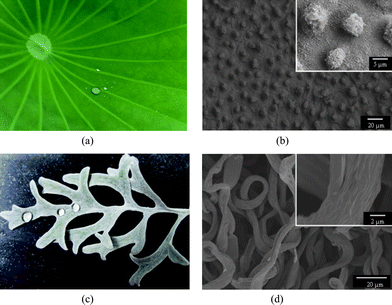 | ||
| Fig. 1 (a) Photographs of the lotus leaf (a) and silver ragwort leaf (c); SEM images of the lotus leaf (b) and silver ragwort leaf (d). | ||
Up to now, many methods have been employed to yield superhydrophobic surfaces, including chemical deposition,1,12 layer-by-layer deposition,5,13 colloidal assembly,14,15 and template-based techniques.16,17 Recently, electrospinning has exhibited lots of advantages for producing polymer or composite nanofibrous mats with high specific surface area and high surface roughness.18,19 Various nanofiber morphologies, such as beaded, smooth, ribbon, as well as porous structures, can be obtained via control of the processing conditions.20–22 Therefore, electrospinning is a versatile and promising approach to developing superhydrophobic surfaces from polymers that feature low surface energies.
Inspired by the lotus leaf, Jiang et al.4 and Acatay et al.23 successfully imitated the lotus-leaf-like structure with superhydrophobicity viaelectrospinning a dilute polymer solution. But the practical applications of these superhydrophobic mats were significantly limited due to their very poor mechanical integrity. Subsequently, Ding et al.10,24 reported the mimicry of silver ragwort leaf with a WCA of 159.5° viaelectrospinning concentrated PS solution. To date, superhydrophobic surfaces with a typical structure of both lotus leaf and silver ragwort leaf have not been reported.
Inspired by the lotus leaf and silver ragwort leaf, here we introduce a facile process to produce superhydrophobic mats with nano-protrusions and numerous grooves (Fig. 2) by a one-step electrospinning of PS solutions incorporating various contents of silica nanoparticles. Moreover, the relationship between the fibrous mat surface hydrophobicity and the fiber surface structures was investigated.
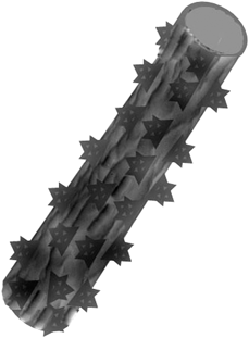 | ||
| Fig. 2 Schematic diagram of the hydrophobic surfaces biomimicked from a combination of the lotus leaf and ragwort leaf. | ||
Fig. 3 displays the PS fibrous mats electrospun from DMF with different contents of silica nanoparticles. As was typical for electrospun fibrous mats, the resultant nanofibers were randomly oriented as three-dimensional porous mats. Fig. 3a shows that the fibrous mats consisted of micro-scaled thick fibers with wrinkled surfaces and thin fibers with smooth surfaces showing much smaller diameters compared with the wrinkled fibers. The difference in the PS fiber diameters could be explained by the occurrence of axial-symmetric instability during the process of the spin jet bending and stretching caused by electrical force.25 A similar result was also found by Gentsch et al.26 in electrospinning of poly(ε-caprolactone) with chloroform. When the fluid jet was ejected into the surrounding, a glassy shell formed on the surface of the fluid jet due to the solvent evaporation and, simultaneously, the solvent trapped inside the jet diffused out from its core to the surface. Thus, a contraction mismatch between the core and shell occurred resulting in the formation of the wrinkled surfaces.27 The typically rough surface of the silver ragwort leaf fibers with nano-scaled grooves along the fiber axis was successfully imitated by creating wrinkles on the surface of the PS fibers (Fig. 1c).
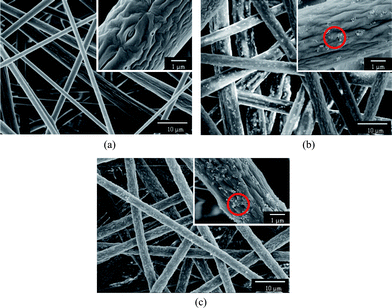 | ||
| Fig. 3 FE-SEM images of PS fibers electrospun from DMF with different contents of silica: (a) 0 wt%, (b) 7.7 wt%, (c) 14.3 wt%. | ||
To realize the mimicry from a combination of both the lotus leaf and silver ragwort leaf (Fig. 2) and thus improve the hydrophobicity of PS fibrous mats, various contents of silica nanoparticles were incorporated into the PS fibers. It was observed that the PS fibers containing 7.7 and 14.3 wt% silica nanoparticles formed from DMF (Fig. 3b and c) showed a uniform fiber diameter in the micrometre range with a protuberant structure. As the silica nanoparticles were introduced in the PS solution, the viscosity of the solution increased. Thus, the instability and stretching of the charged jets were weakened, leading to the formation of uniform fibers. After silica nanoparticle loading, silica particles in clusters of varying sizes (50 nm–1.2 μm) were immobilized onto the surface of the groove-like structured PS fibers. The silica nanoparticles bulged on the surfaces of fibers (indicated by dotted circle, Fig. 3b and c) creating enhanced surface roughness and additional surface area, which may significantly boost the superhydrophobic properties.
To confirm the presence of silica nanoparticles in the PS fibers, FTIR spectroscopy was also performed. Fig. 4 provided the infrared spectra of the PS fibrous mats containing various contents of silica formed from DMF. It could be clearly observed that the most significant difference in the spectra was the peak at 1107 cm−1, which was the feature of Si–O–Si bond asymmetric stretching vibration and only existed in the composite PS/silica microfibers. A similar phenomenon was also reported widely in the preparation of silica nanofibers in the literature.28,29
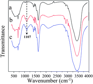 | ||
| Fig. 4 FT-IR spectra of the PS fibrous mats electrospun from DMF with different contents of silica: (a) 0 wt%, (b) 7.7 wt%, (c) 14.3 wt%. | ||
A comparison between Fig. 3b and Fig. 3c clearly illustrated that the amount of silica nanoparticles bulged on the fiber surfaces was increased with increasing the contents of silica nanoparticles. The AFM images of PS fibrous mats formed from DMF containing various silica nanoparticles also supported these observations (Fig. 5). From AFM images, we found that the surface roughness of these PS fibers gradually increased as the silica content increased, due to the formation of nano-protrusions on the fiber surfaces. This was reasonably due to the higher boil point solvent DMF (153 °C) used.22 Because of its low evaporation rate, the solvent DMF trapped inside the jet needed a longer time to diffuse out. The longer diffusing time of solvent might provide sufficient time and opportunity for the phase separation and for silica nanoparticles to move toward the fiber surfaces, accompanying the solvent, showing the bulged silica nanoparticles on the fiber surfaces as nano-protrusions.
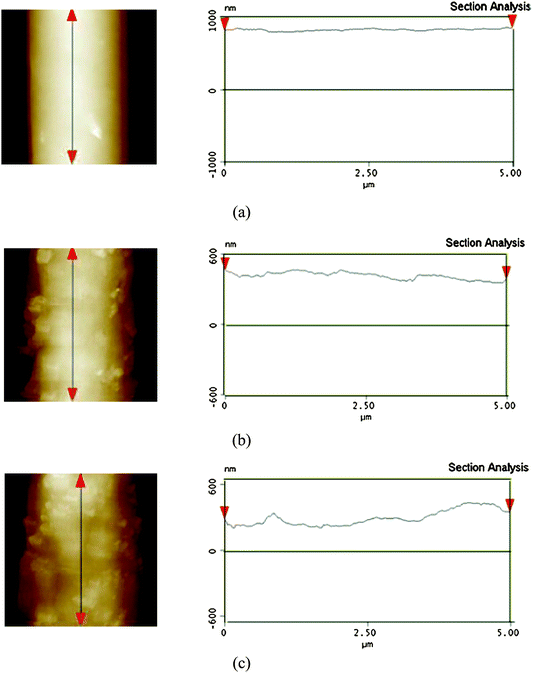 | ||
| Fig. 5 AFM images (5 μm × 5 μm) of surface topography and corresponding cross-sectional profiles along the marked fiber axis of the PS fibers electrospun from DMF with different contents of silica: (a) 0 wt%, (b) 7.7 wt%, (c) 14.3 wt%. | ||
WCA measurements revealed that the PS fibrous mats formed from DMF fibrous mats show a hydrophobicity with a WCA of 147.6° (Fig. 6). The selected water droplet images were shown as the inset. The hydrophobicity of the PS fibrous mats was ascribed to the low surface energy of the PS and the wrinkles on the PS fiber surfaces.10 A further increased surface hydrophobicity (WCAs of 153.3° and 157.2°) was observed with PS fibrous mats containing 7.7 and 14.3 wt% silica nanoparticles. This was attributed to the increased fiber surface roughness caused by the wrinkles and nano-protrusions (Fig. 3b and c), which trapped more air under the water droplets that fell on the fibers. It is worth noting that PS fibrous mats containing 14.3 wt% silica nanoparticles exhibited a stable superhydrophobic state with a WCA (157.2°) approaching that (160°) of the lotus leaf.4 Compared with previous publications for fabricating superhydrophobic mats with a rough surface (WCA of 155 ± 1.6°) by electrospinning PS solution from THF,7 the PS fibrous mats containing silica nanoparticles showed a larger WCA of up to 157.2° and a good mechanical integrity. Moreover, this was a relatively facile approach to prepare superhydrophobic surfaces in contrast to the decoration of fibers with silica nanoparticlesvia a layer-by-layer deposition technique.5 The variation of the WCAH of PS fibrous mats containing various silica nanoparticles was shown in Fig. 5b. The WCAH was found to decrease concurrently with the increase of the surface roughness. The PS fibrous mats containing 14.3 wt% silica nanoparticles showed the lowest WCAH of 2.2°. The result particularly highlights that the biomimicry of a combination of the lotus leaf and silver ragwort leaf have been realized in this study, which could be easily extended to the production of superhydrophobic surfaces for various polymeric materials. The large-scale PS fibrous mats formed from DMF with 7.7 wt% silica and their superhydrophobicity are shown in the image of Fig. S1,† which was taken by a conventional digital camera.
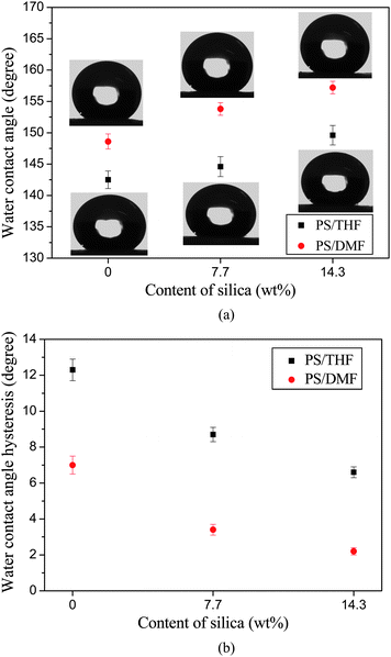 | ||
| Fig. 6 (a) WCA and corresponding shapes of water droplets for the electrospun PS fibrous mats with respect to the contents of silica. (b) WCAH for the electrospun PS fibrous mats with respect to the contents of silica. | ||
The effect of roughness on hydrophobicity was established by Wenzel,30 who described the relationship between the WCA on a rough surface (cos θW) and a corresponding flat surface (cos θY) composed of a solid and air as the following equation:
| cos θW = rcos θY | (1) |
Cassie and Baxter also proposed a model for description of the surface wettability,31 hydrophobicity was relevant to the surface area between the water and the material. The WCA for a surface can be expressed as eqn (2)
| cos θ′ = f1cos θ − f2 | (2) |
In eqn (2), θ′ and θ are the WCA on a rough surface and flat surface, respectively. f1 and f2 are the ratios of solid/water interface and air/water interface, respectively, and f1 + f2 = 1. Given the WCA of the flat PS film (95°) and PS fibrous mat (157.2°), f2 was calculated to be 0.916. This indicated that the air trapped in the rough micro/nanostructures of the PS fibrous mats was the key factor affecting the superhydrophobicity.
To regulate the fine surface structure of PS fibers, we prepared the PS fibrous mats with various contents of silica nanoparticles formed from THF (Fig. 7). As shown in Fig. 7a, the PS fibrous mats formed from highly volatile solvent THF displayed a flat shape with numerous nanopores densely distributed on the surfaces. When the fluid jet ejected from the Taylor cone formed at the tip of the needle, the THF evaporated rapidly from the jet surface leading to the formation of a skin layer.32 Meanwhile, the solvent trapped by the skin layer diffused very quickly outward together with the air and vapor penetration inward.22,33 As a result, the atmospheric pressure collapsed the jet, forming a flat shape. Additionally, the rapid phase separation and solidification on the surfaces of the fluid jets in electrospinning had been ascribed to the formation of nanopores on the fiber surfaces.22,34–37 It was seen that the PS fibrous mats containing 7.7 and 14.3 wt% silica formed from THF transformed from a uniform flat shape to irregular flat shape with a dent-like structure (Fig. 7b and c).
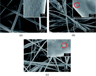 | ||
| Fig. 7 FE-SEM images of PS fibers electrospun from THF with different contents of silica: (a) 0 wt%, (b) 7.7 wt%, (c) 14.3 wt%. | ||
Different to PS fibrous mats containing silica nanoparticles formed from DMF (Fig. 3b and c), only a small amount of silica is present on the fiber surface (indicated by dotted circles, insets of Fig.7b and c). The solvent THF with a low boiling point (66 °C) evaporated very quickly, which provided insufficient time for nonsolvent penetration into the fluid jet, inducing phase separation before polymer solution solidification.21 As a result, most of the silica nanoparticles embedded inside in the polymer matrix and only a handful of silica bulged on the surfaces of as-spun fibers due to the rapid solidification caused by the fast solvent evaporation.
As shown in Fig. 6, the PS fibrous mats formed from THF showed a WCA of 142.5°. When the 7.7 wt% silica nanoparticles were incorporated into the PS fibers, the WCA was slightly increased to 144.6° due to the small amount of silica bulging on the fiber surfaces (indicated by dotted circles, inset of Fig. 7b). Further increasing the content of silica nanoparticles (14.3 wt%) resulted in much more silica being present on the fiber surfaces (inset of Fig. 7c) and thus a WCA of 149.6° (Fig. 6a). It was clearly seen that the WCA of the PS fibrous mats formed from THF was much smaller than that of fibrous mats formed from DMF due to the absence of nano-protrusions and numerous grooves.
In summary, we successfully fabricated biomimetic superhydrophobic surfaces by tuning the contents of silica nanoparticles in electrospinning PS solutions. The contents of silica nanoparticles and the kind of solvent proved to be the key factors affecting the fiber surface morphology and hydrophobicity. The hydrophobicity of PS fibrous mats was found to increase concurrently with the increasing of fiber surface roughness due to the use of DMF or the incorporation of silica nanoparticles. The PS fibrous mats containing 14.3 wt% silica nanoparticles showed the highest WCA of 157.2° and lowest WCAH of 2.2°. The facile and simple method makes it suitable for the practical application of superhydrophobic surfaces with a large area.
Acknowledgements
This work is supported by the National Natural Science Foundation of China (No. 50803009 and 10872048), the “111 Project” (No. 111-2-04 and B07024), the Shanghai Committee of Science and Technology (No. 10JC1400600), the National Basic Research Program of China (973 Program, 2011CB606100), and the Fundamental Research Funds for the Central Universities.References
- A. Nakajima, A. Fujishima, K. Hashimoto and T. Watanabe, Adv. Mater., 1999, 11, 1365–1368 CrossRef CAS.
- M. Miwa, A. Nakajima, A. Fujishima, K. Hashimoto and T. Watanabe, Langmuir, 2000, 16, 5754–5760 CrossRef CAS.
- B. Ding, M. R. Wang, X. F. Wang, J. Y. Yu and G. Sun, Mater. Today, 2010, 13, 16–27 CrossRef CAS.
- L. Jiang, Y. Zhao and J. Zhai, Angew. Chem., Int. Ed., 2004, 43, 4338–4341 CrossRef CAS.
- M. L. Ma, M. Gupta, Z. Li, L. Zhai, K. K. Gleason, R. E. Cohen, M. F. Rubner and G. C. Rutledge, Adv. Mater., 2007, 19, 255–259 CrossRef CAS.
- X. M. Li, D. Reinhoudt and M. Crego-Calama, Chem. Soc. Rev., 2007, 36, 1350–1368 RSC.
- C. W. Tu, C. H. Tsai, C. F. Wang, S. W. Kuo and F. C. Chang, Macromol. Rapid Commun., 2007, 28, 2262–2266 CrossRef CAS.
- Y. Zhu, J. C. Zhang, Y. M. Zheng, Z. B. Huang, L. Feng and L. Jiang, Adv. Funct. Mater., 2006, 16, 568–574 CrossRef CAS.
- Z. Z. Gu, H. M. Wei, R. Q. Zhang, G. Z. Han, C. Pan, H. Zhang, X. J. Tian and Z. M. Chen, Appl. Phys. Lett., 2005, 86.
- Y. Miyauchi, B. Ding and S. Shiratori, Nanotechnology, 2006, 17, 5151–5156 CrossRef CAS.
- X. H. Li, B. Ding, J. Y. Lin, J. Y. Yu and G. Sun, J. Phys. Chem. C, 2009, 113, 20452–20457 CrossRef CAS.
- X. F. Wu and G. Q. Shi, J. Phys. Chem. B, 2006, 110, 11247–11252 CrossRef CAS.
- T. Ogawa, B. Ding, Y. Sone and S. Shiratori, Nanotechnology, 2007, 18, 165607 CrossRef.
- G. Zhang, D. Y. Wang, Z. Z. Gu and H. Mohwald, Langmuir, 2005, 21, 9143–9148 CrossRef CAS.
- J. Li, J. Fu, Y. Cong, Y. Wu, L. Xue and Y. Han, Appl. Surf. Sci., 2006, 252, 2229–2234 CrossRef CAS.
- J. Y. Shiu, C. W. Kuo, P. L. Chen and C. Y. Mou, Chem. Mater., 2004, 16, 561–564 CrossRef CAS.
- H. Yan, K. Kurogi, H. Mayama and K. Tsujii, Angew. Chem., Int. Ed., 2005, 44, 3453–3456 CrossRef CAS.
- D. H. Reneker and I. Chun, Nanotechnology, 1996, 7, 216–223 CrossRef CAS.
- D. Li and Y. N. Xia, Nano Lett., 2004, 4, 933–938 CrossRef CAS.
- C. L. Casper, J. S. Stephens, N. G. Tassi, D. B. Chase and J. F. Rabolt, Macromolecules, 2004, 37, 573–578 CrossRef CAS.
- C. L. Pai, M. C. Boyce and G. C. Rutledge, Macromolecules, 2009, 42, 2102–2114 CrossRef CAS.
- J. Y. Lin, B. Ding, J. Y. Yu and Y. Hsieh, ACS Appl. Mater. Interfaces, 2010, 2, 521–528 CrossRef CAS.
- K. Acatay, E. Simsek, C. Ow-Yang and Y. Z. Menceloglu, Angew. Chem., Int. Ed., 2004, 43, 5210–5213 CrossRef CAS.
- M. Sun, X. H. Li, B. Ding, J. Y. Yu and G. Sun, J. Colloid Interface Sci., 2010, 347, 147–152 CrossRef CAS.
- Y. M. Shin, M. M. Hohman, M. P. Brenner and G. C. Rutledge, Appl. Phys. Lett., 2001, 78, 1149–1151 CrossRef CAS.
- R. Gentsch, B. Boysen, A. Lankenau and H. G. Borner, Macromol. Rapid Commun., 2010, 31, 59–64 CrossRef CAS.
- L. F. Wang, C. L. Pai, M. C. Boyce and G. C. Rutledge, Appl. Phys. Lett., 2009, 94, 151916 CrossRef.
- M. Kanehata, B. Ding and S. Shiratori, Nanotechnology, 2007, 18, 315602 CrossRef.
- M. Guo, B. Ding, X. H. Li, X. L. Wang, J. Y. Yu and M. R. Wang, J. Phys. Chem. C, 2010, 114, 916 CrossRef CAS.
- R. Wenzel, Ind. Eng. Chem., 1936, 28, 988–994 CrossRef CAS.
- A. Cassie and S. Baxter, Trans. Faraday Soc., 1944, 40, 546–551 RSC.
- S. Koombhongse, W. Liu and D. H. Reneker, J. Polym. Sci., Part B: Polym. Phys., 2001, 39, 2598–2606 CrossRef CAS.
- A. Guenthner, S. Khombhongse, W. Liu, P. Dayal, D. Reneker and T. Kyu, Macromol. Theory Simul., 2006, 15, 87–93 CrossRef CAS.
- M. Bognitzki, W. Czado, T. Frese, A. Schaper, M. Hellwig, M. Steinhart, A. Greiner and J. H. Wendorff, Adv. Mater., 2001, 13, 70–72 CrossRef CAS.
- S. Megelski, J. S. Stephens, D. B. Chase and J. F. Rabolt, Macromolecules, 2002, 35, 8456–8466 CrossRef CAS.
- P. Dayal, J. Liu, S. Kumar and T. Kyu, Macromolecules, 2007, 40, 7689–7694 CrossRef CAS.
- J. Y. Lin, B. Ding, J. Y. Yu, G. C. Wu, J. M. Yang and G. Sun, Int. J. Nonlinear Sci. Numer. Simul., 2010, 11, 523–527 Search PubMed.
Footnote |
| † Electronic supplementary information (ESI) available: Preparation procedure and characterization of microfibrous polystyrene mats. See DOI: 10.1039/c0nr00812e |
| This journal is © The Royal Society of Chemistry 2011 |
