On-chip magnetically actuated robot with ultrasonic vibration for single cell manipulations†
Masaya
Hagiwara
*a,
Tomohiro
Kawahara
b,
Yoko
Yamanishi
b,
Taisuke
Masuda
b,
Lin
Feng
b and
Fumihito
Arai
bc
aDepartment of Mechanical Science and Engineering, Nagoya University, Nagoya, Japan. E-mail: hagiwara@biorobotics.mech.nagoya-u.ac.jp; Fax: +81-52-789-5213; Tel: +81-52-789-5656
bDepartment of Micro-Nano Systems Engineering, Nagoya University, Nagoya, Japan
cSeoul National University, Seoul, Korea
First published on 12th May 2011
Abstract
This paper presents an innovative driving method for an on-chip robot actuated by permanent magnets in a microfluidic chip. A piezoelectric ceramic is applied to induce ultrasonic vibration to the microfluidic chip and the high-frequency vibration reduces the effective friction on the MMT significantly. As a result, we achieved 1.1 micrometre positioning accuracy of the microrobot, which is 100 times higher accuracy than without vibration. The response speed is also improved and the microrobot can be actuated with a speed of 5.5 mm s−1 in 3 degrees of freedom. The novelty of the ultrasonic vibration appears in the output force as well. Contrary to the reduction of friction on the microrobot, the output force increased twice as much by the ultrasonic vibration. Using this high accuracy, high speed, and high power microrobot, swine oocyte manipulations are presented in a microfluidic chip.
Introduction
A micromechanical manipulator is widely used for medical and life science applications because of its capability for high accuracy, high power output, and flexibility of the manipulation.1–4 However, the manipulation is conducted in an environment open to the air due to the huge size of the manipulator and it leads to cell contamination issues. In addition, the manipulation requires a high skill of the operator because the manipulator has to be controlled in 6 degrees of freedom. On the other hand, cell manipulations in the confined space of a microfluidic chip have great advantages in the field of biotechnology because of the low contamination, repeatability, and high throughput ability.5–7 Especially robots on a chip have great advantages for the treatment of biological cells instead of human handling due to their non-skill dependence, high throughput and high repeatability.8 However, the applications of the existing on-chip robots are limited due to insufficient amount of force or spatial resolution.Magnetic fields can be one of the suitable power sources for an on-chip robot because of their non-contact drive, low invasiveness with respect to a cell, and low production cost. Thus, a considerable amount of research has been carried out on magnetic actuators.9–16 A magnetically driven microtool (MMT) actuated by a permanent magnet can output a force of the order of millinewtons, which is in keeping with the small size of the drive unit. In fact, a permanent magnet possesses a magnetic field that is more than ten times the strength of a magnetic field of an electromagnetic coil of the same size.17,18 Therefore, an MMT driven by a permanent magnet can be applied to a wide range of cell manipulations such as loader, sorter, droplet generation, etc.19–21
However, the disadvantages associated with an MMT driven by permanent magnets are the low positioning accuracy and response speed against the drive stage. The low performance of an MMT is attributed to the fact that the applied friction force is relatively large compared to the magnetic force in the driving direction component. When an MMT is driven by a permanent magnet on the XY stages from beneath the chip, there is an area where the MMT is not driven when the magnet passes under the MMT; the so-called “dead band”. The dead band interferes with the precise positioning of the MMT on a chip and leads to a deterioration in the effective control of the MMT as a robot on a chip because of the slow response speed to the driver unit.
We have previously developed a horizontally arranged permanent magnet drive in order to reduce the friction on an MMT and supply a greater magnetic force into the driving direction;22 however, the positioning accuracy remains in the order of dozens of micrometres leading to difficulties in treating smaller cells.
Herein, we describe an innovative drive method for an MMT driven by permanent magnets in order to achieve a precise positioning accuracy in the order of micrometres with keeping a strong output force from the permanent magnets. Fig. 1 shows the conceptual overview of the cell manipulation by the MMTs. The MMTs are placed in a microfluidic chip and actuated by permanent magnets set on linear stages. Then, the MMT manipulates the inserted cells under the microscope just like a micromechanical manipulator does, but the size of the manipulator is significantly smaller and the environment is stabler than a micromechanical manipulator owing to the closed space of the microfluidic chip.
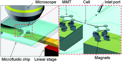 | ||
| Fig. 1 Conceptual overview of the cell manipulation by the MMTs in a microfluidic chip. The MMTs actuated by permanent magnets can conduct the wide range of cell manipulations substituting for the mechanical micromanipulator. | ||
In order to counter the low positioning accuracy of the permanent magnet drive, ultrasonic vibration is employed to reduce the effective friction on the MMT. The MMT can be applied to a wide range of cell manipulations substituting for a micromanipulator once the friction on the MMT reduces because of its high spatial resolution and strong output force.
Friction reduction by ultrasonic vibration
When ultrasonic vibration is applied to the sliding surface of a moving object, the direction of the friction on the object switches from ten thousand to a million times per second and as a result, the effective friction decreases significantly.23–27 Littmann et al.25,26 developed an analytical model to explain the phenomenon of friction reduction and demonstrated that the reduction ratio depends on the velocity ratio of the moving object and the sliding surface. Kumar also developed an analytical model and expressed the friction reduction ratio as follows;27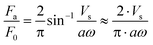 | (1) |
Under microscale conditions, friction is the dominant contributor in the deterioration of the positioning accuracy due to the scale effect. Thus, the friction reduction by vibration can be expected to have a considerable impact on the positioning accuracy in the microscale. Here, we apply this phenomenon to the microfluidic chip to reduce the effective friction on the MMT considerably. Fig. 2 shows the driving concept of the MMT with ultrasonic vibration. Radially displaceable piezoelectric ceramic is attached to the glass substrate under the microfluidic chip and oscillates the sliding surface of the MMT. The MMT is actuated by permanent magnets whose axis is set to the horizontal direction and the permanent magnet is placed on the 2-DOF linear stage.
 | ||
| Fig. 2 Driving concept of the MMT actuated by a permanent magnet with ultrasonic vibration. Oscillating the glass substrate by the piezoelectric ceramic reduces the effective friction on the MMT. | ||
Experimental evaluation
Experimental setup
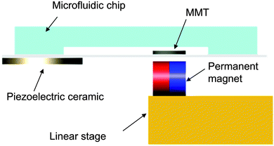
In the previous study,22 we developed the driving method using horizontally arranged permanent magnets, which is called horizontal polar drive (HPD), and improved the positioning accuracy by reducing the friction on the MMT. Fig. 3(a) and (b) show the multi-degree of freedom (DOF) MMT with HPD. Fig. 3(c) shows the fabrication process of the Ni based MMT. The sacrificial layer (LOR 5B, Tokyo Ohka Kogyo Co., Ltd) is coated on Si wafer. Cr–Au is then sputtered on the wafer (thickness = 300 nm). The photoresist (KMPR 1035, Nippon Kayaku Co., Ltd) is subsequently coated on the substrate. After the exposure, the KMPR pattern is developed. Finally Ni is grown by electroplating (=75 μm). After removing the photoresist and sacrificial layer, the Ni parts can be collected and ultrasonically cleaned. | ||
| Fig. 3 The design of MMT and the characteristic of the piezoelectric ceramic. (a) Concept of the multi-DOF MMT. (b) Top view of the actual design and permanent magnets setup. (c) Fabrication process of the Ni based MMT. (d) Frequency characteristics of the piezoelectric ceramic. | ||
In addition to HPD, commercially available piezoelectric ceramic (W-40, MKT Taisei Co.), of dimensions ϕ 42.0 × 3.5 mm was used in the experiments in order to reduce the effective friction on the MMT and improve the positioning accuracy. The resonance frequency of the ceramic was 55 kHz, and the electrostatic capacitance was 4600 pF. Fig. 3(d) shows the frequency characteristic of the piezoelectric ceramic under different applied voltages. It can be seen that the vibration amplitude is significantly increased around the resonance frequency and the magnitude is approximately 1.4 μm when 300 Vp–p (peak to peak) AC voltage is applied. Therefore, it is assumed that the vibration amplitude is not large enough to affect the cell manipulation when the ceramic mentioned above is used. Four neodymium (Nd2Fe14B) magnets (diameter: 1.0 mm, grade: N40) were employed as a drive magnet. A Ni based multi-DOF MMT, which is described in Fig. 3(a) and (b), was used for the evaluation.
Evaluation of the effect of the ultrasonic vibration for the MMT accuracy
An experiment was conducted in order to evaluate the effect of the ultrasonic vibration and the improvement of the MMT positioning accuracy. The linear stage was actuated in a circular trajectory with the constant drive velocity and the corresponding MMT positions were measured by a CCD camera. The four ϕ 1.0 mm × 1.0 mm columnar neodymium magnets were used as the drive unit. Fig. 4(a) shows the MMT positioning accuracy without vibration by piezoelectric ceramic against the circular target trajectory (radius: 0.5 mm). The drive velocity of the linear stage was 0.785 mm s−1 in the x–y direction. The measurements were conducted in 100 points. Then, the maximum error between the targets and the actual MMT position was approximately 120 μm. However, when vibration was applied to the microfluidic chip, the MMT movement was significantly improved. Fig. 4(b) shows the MMT positioning accuracy when 300 Vp–p was applied to the piezoelectric ceramic with 55 kHz frequency. The drive stage configuration was the same as Fig. 4(a) but the maximum error between the targets and the actual trajectory was 9.5 μm, which was more than 10 times greater accuracy than in the case without vibration.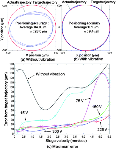 | ||
| Fig. 4 Evaluation result of the MMT positioning error from target trajectory. (a) Comparison of the trajectory between the target and the actual in the case without vibration. (b) Comparison of the trajectory between the target and the actual in the case with vibration (frequency: 55 kHz, applied voltage: 300 Vp–p). (c) Correlation of the maximum positioning error and the drive velocity in different applied voltages (frequency: 55 kHz). | ||
Note that the total positioning accuracy included not only the MMT positioning error, but also other factors such as the measuring error and the stage positioning error. The measuring error was approximately 4 μm due to 2.5 μm per pixel of the display from the CCD camera and the linear stage positioning error was approximately 5 μm. Thus, the positioning error of the MMT itself under the above conditions can be calculated by root-mean-square error as follows;
 | (2) |
According to eqn (1), the friction reduction ratio is a function of the vibration amplitude and the velocity of the MMT. Fig. 4(c) shows maximum error of the MMT itself (eMMT). The error eMMT was calculated by eqn (2) after 100 points measuring by the CCD camera under various applied voltages (15, 75, 150, 225 and 300 Vp–p) to the piezoelectric ceramic and under various drive velocities (0.16, 0.47, 0.79, 1.57, 2.36, 3.14, 3.93, 4.71 and 5.50 mm s−1) of the stage respectively and the data were interpolated by cubic spline curves.
The positioning error increases with increasing stage velocity, and decreases with increasing applied voltage, which represents the vibration amplitude at the sliding surface. In the case without vibration, the result corresponds to the Stribeck curve28,29 and it is reasonable that the positioning error increases according to the friction. The result in the case with vibration broadly corresponds to eqn (1); however, the positioning accuracy with lower applied voltages is more precise than when a higher voltage is applied in the region of the low stage velocity. This can be attributed to the fact that the positioning accuracy is nearing the amplitude of the vibrations. In fact, the positioning accuracy of the MMT is 1.1 μm when the applied voltage is 15 Vp–p and the stage velocity is 0.16 mm s−1, but it is impossible to achieve this accuracy when the applied voltage is 300 Vp–p due to ±1.4 μm displacement of the piezoelectric ceramic as shown in Fig. 3(d). Consequently, the error at 0.16 mm s−1 stage velocity became less than 1 percent of the case without vibration when 15 Vp–p is applied.
Evaluation of the effect of the ultrasonic vibration on the MMT actuation speed
In addition to the achievement of the micrometre order positioning accuracy, other benefits of the ultrasonic vibration can be also observed. The response speed increases as well because of the significantly decreased friction on the MMT. Fig. 5 shows the high speed MMT movement in 3-DOF with ultrasonic vibration. 150 Vp–p was applied to the piezoelectric ceramic with 55 kHz frequency. Owing to the high response speed of the MMT against the drive stages, it is confirmed that the MMT can follow the drive stage up to 5 Hz, which is the upper limit of the drive stage used in the experiments (see ESI†). Consequently, the high speed actuation leads to the high throughput operation in a microfluidic chip.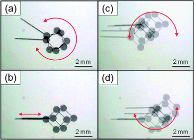 | ||
| Fig. 5 High speed 3-DOF movement of MMT (the rotation speed: 500 rpm, maximum speed: 5.5 mm s−1) (see ESI†). | ||
Evaluation of the effect of the ultrasonic vibration on the output force
The output force of the MMT is also experimentally evaluated using the loadcell (LVS-5GA, Kyowa Electronic Instruments Co. Ltd). Fig. 6 shows the output forces of the MMT with and without ultrasonic vibration respectively. The drive unit and MMT configuration were the same as Fig. 3. The output force of the MMT with ultrasonic vibration (150 Vp–p, 55 kHz) increased twice as much instead of the friction reduction. Compared to the other microactuators, the output force of the MMT is considerably higher and it can reach in the order of mN force. Increasing the capacity of the maximum force enables the MMT to apply to the force requirement tasks, such as a cell cutting operation and mechanical stimulation to the microorganism.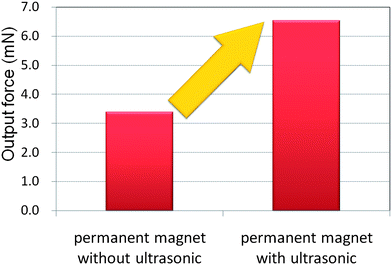 | ||
| Fig. 6 Experimentally measured output force with and without vibration. | ||
High power output and precise positioning accuracy allow the MMT to be employed in a wide range of applications like commercialized micromechanical manipulators. The differences are that the size of the manipulator is tiny for the MMT and it can be actuated in a microfluidic chip. A closed environment supplies a less disturbing atmosphere to prevent cell contamination and miniaturization of the manipulator leads to the high throughput of the operations.7
Vibration toxicity test for biological cells
The friction reduction counts for nothing if the applied vibration makes negative effects on cells. Thus, the vibration toxicity test was conducted by examining cell propagation. Six wells of chondrocytes (5000 cells per well) were prepared and cultured in an incubator for 24 hours in advance. The vibration with 55 kHz frequency and 1.2 μm amplitude was applied to three of them after 6, 12, 24, 48, 72 hours for 10 minutes respectively and nothing applied to the others. The WST-8 assay (Cell Counting Kit-8, Dojindo Co.), which is commonly used for cell toxicity test, was added to the wells and the absorption of light with 450 nm wavelength was measured by a plate reader in order to count the number of live cells.30,31Fig. 7 shows the comparison of the cell propagation with and without vibration. According to this result, there is no difference in cell growth rate between the groups with and without vibration. It implies that the vibration does not have a negative effect on the cell growth. This result indicates that the vibration is applicable to cell manipulation since the actual duration of the vibration is only a few seconds per cell.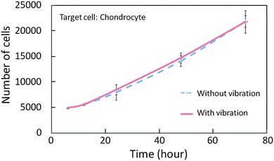 | ||
| Fig. 7 Vibration toxicity test result for cells (target cell: chondrocyte). | ||
Applications to cell manipulation
Experiments were conducted to show that the MMT has the capability to manipulate cells instead of the conventional micromechanical manipulators. Swine oocytes were targeted because it requires a large amount of force to manipulate due to the relatively large size of the cell.The MMTs were actuated by permanent magnets set on the XY linear stages and the stages were teleoperated by joysticks. AC 150 Vp–p with 55 kHz was applied to vibrate the sliding surface of MMTs. The same piezoelectric ceramic as employed in previous experiments was attached to the microfluidic chip. The MMTs and the drive magnets were of the same configurations as mentioned in the previous section but only the tip of the MMTs was modified in accordance with the applications.
Fig. 8shows the experimental result of the swine oocyte manipulation in a microfluidic chip. Fig. 8(a) shows the MMTs rotate the oocyte to control its posture by crossing the MMTs. Fig. 8(b) shows that the MMTs array oocytes in a geometric shape. The MMTs were operated like chopsticks to pick and place the oocyte one by one. Fig. 8(c) shows the cutting stained oocyte to remove the nucleus. This operation requires enough amount of force17 and the MMTs satisfy the requirement. The swine oocyte was easily cut by the MMT in a few seconds (see ESI†).
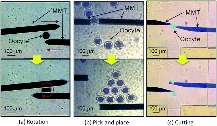 | ||
| Fig. 8 Cell manipulations in a microfluidic chip by MMTs. (a) The posture of the oocyte is controlled by MMT. (b) The MMTs pick and place the oocytes to arrange precisely. (c) The stained oocyte is cut into two to remove the nucleus from the oocyte (see ESI†). The cost of the microfluidic chip and MMT is inexpensive and therefore they are disposed after the experiments to maintain a clean condition without washing. | ||
Conclusions
In this paper, we described an innovative drive method for MMTs actuated by permanent magnets with ultrasonic vibration applied to the microfluidic chip. The positioning accuracy improved by up to 100 times than in the case without vibration. The minimum positioning accuracy for the MMT itself was 1.1 μm. In addition to the precision, the response speed was also improved and high speed actuation was achieved. The vibration also increased the output force of the MMT as well as friction reduction and we validated the MMT could output several millinewtons. A wide range of applications for cell manipulations can be achieved in a microfluidic chip owing to the high power output (mN order), high precision (μm order), and high speed (up to 5.5 mm s−1) reported. Here, we demonstrated several applications for swine oocyte manipulations. Oocytes were precisely rotated, arranged, and cut by a dual-arm MMT in a closed environment of the microfluidic chip.Unlike conventional operation, on-chip cell manipulation can be conducted as a flow process and cells can be supplied to the manipulation area from one second to the next. Therefore, the throughput of the process can be increased significantly once the system is setup. Then, this precisely controlled MMT is a promising tool to develop high speed and high throughput automation processes. It is our future work to establish the fully automated on-chip cell manipulation like a production line of the manufacturing.
Acknowledgements
This work is partially supported by SENTAN, JST, and the Nagoya University Global COE program for Education and Research of Micro-Nano Mechatronics.References
- T. Wakayama, A. C. F. Perry, M. Zuccotti, K. R. Johnson and R. Yanagimachi, Nature, 1998, 394, 369–374 CrossRef CAS.
- Y. Murayama, C. E. Constantinou and S. Omata, J. Biomech., 2004, 37, 67–72 CrossRef.
- Y. Sun, K. T. Wan, K. P. Roberts, J. C. Bischof and B. J. Nelson, IEEE Trans. NanoBiosci., 2003, 2, 279–286 CrossRef.
- K. Yanagida, H. Katayose, H. Yazawa, Y. Kimura, K. Konnai and A. Sato, Hum. Reprod., 1998, 14, 448–453 CrossRef.
- J. Castillo, M. Dimaki and W. E. Svendsen, Integr. Biol., 2009, 1, 30–42 RSC.
- J. P. Desai, A. Pillarisetti and A. D. Brooks, Annu. Rev. Biomed. Eng., 2007, 9, 35–53 CrossRef CAS.
- W. S. N. Trimmer, Sens. Actuators, 1988, 19, 267–287.
- J. J. Abbott, Z. Nagy, F. Beyeler and B. J. Nelson, IEEE Rob. Autom. Mag., 2007, 92–103 Search PubMed.
- J. J. Abbott, K. E. Peyer, M. C. Lagomarsino, L. Zhang, L. Dong, I. K. Kaliakatsos and B. J. Nelson, Int. J. Rob. Res., 2009, 28, 1434–1447 CrossRef.
- J. Atencia and D. J. Beebe, Lab Chip, 2010, 4, 598–602 Search PubMed.
- A.-L. Gassner, M. Abonnenc, H.-X. Chen, J. Morandini, J. Josserand, J. S. Rossier, J.-M. Busnel and H. H. Girault, Lab Chip, 2009, 9, 2356–2363 RSC.
- G. A. Mensing, T. M. Pearce, M. D. Graham and D. J. Beebe, Philos. Trans. R. Soc. London, Ser. A, 2004, 362, 1059–1068 CrossRef.
- C. Pawashe, S. Floyd and M. Sitti, Int. J. Rob. Res., 2009, 28, 1077–1094 CrossRef.
- M. Gauthier and E. Piat, J. Micromechatronics, 2004, 2, 87–119.
- M. Roper, R. Dreyfus, J. Baudry, M. Fermigier, J. Bibette and H. A. Stone, J. Fluid Mech., 2006, 554, 167–190 Search PubMed.
- L. Zhang, K. E. Peyer and B. J. Nelson, Lab Chip, 2010, 10, 2203–2216 RSC.
- N. Inomata, T. Mizunuma, Y. Yamanishi and F. Arai, J. Microelectromech. Syst., 2010, 20, 383–388.
- O. Cugat, J. Delamare and G. Reyne, IEEE Trans. Magn., 2003, 39, 3607–3612 CrossRef.
- Y. Yamanishi, L. Feng and F. Arai, Advanced Robotics, 2010, 24, 2005–2018 CrossRef.
- Y. Yamanishi, S. Sakuma, Y. Kihara and F. Arai, J. Microelectromech. Syst., 2010, 19, 350–356 CrossRef.
- Y. Yamanishi, S. Sakuma, K. Onda and F. Arai, Journal of Micro-Nano Mechatronics, 2008, 4, 49–57 Search PubMed.
- M. Hagiwara, T. Kawahara, Y. Yamanishi and F. Arai, Appl. Phys. Lett., 2010, 97, 013701 CrossRef.
- F. Dinelli, S. K. Biswas, G. A. D. Briggs and O. V. Kolosov, Appl. Phys. Lett., 1997, 71, 3.
- K. F. Bohringer, K. Goldberg, M. Cohn, R. Howe and A. Pisano, Parallel Microassembly with Electrostatic Force Fields, Leuven, Belgium, 1998 Search PubMed.
- W. Littmann, H. Storck and J. Wallaschek, Arch. Appl. Mech., 2001, 71, 549–554 CrossRef.
- H. Storck, W. Littmann, J. Wallaschek and M. Mracek, Ultrasonics, 2002, 40, 379–383 CrossRef CAS.
- V. Kumar, Tribol. Int., 2004, 37, 833–840 CrossRef CAS.
- E. R. M. Gelinck and D. J. Schipper, Tribol. Int., 2000, 33, 175–181 CrossRef.
- X. Lu, M. M. Khonsari and E. R. M. Gelinck, J. Tribol., 2006, 128, 789–794 CrossRef.
- T. Nakagawa, M. Takahashi, T. Ozaki, K. i. Watanabe, S. Todo, H. Mizuguchi, T. Hayakawa and A. Nakagawara, Mol. Cell. Biol., 2002, 22, 2575–2585 CrossRef CAS.
- D. M. Kuhn, M. Balkis, J. Chandra, P. K. Mukherjee and M. A. Ghannoum, J. Clin. Microbiol., 2003, 41, 506–508 CrossRef CAS.
Footnote |
| † Electronic supplementary information (ESI) available: The multimedia video file is available online to show the high speed actuation of the MMT and its cell manipulations. See DOI: 10.1039/c1lc20164f |
| This journal is © The Royal Society of Chemistry 2011 |