Large-scale mechanical peeling of boron nitride nanosheets by low-energy ball milling†
Lu Hua
Li
*a,
Ying
Chen
a,
Gavin
Behan
b,
Hongzhou
Zhang
b,
Mladen
Petravic
c and
Alexey M.
Glushenkov
a
aInstitute for Technology Research and Innovation, Deakin University, Geelong Waurn Ponds Campus, VIC 3216, Australia. E-mail: luhua.li@deakin.edu.au
bSchool of Physics and CRANN, Trinity College Dublin, College Green, Dublin 2, Republic of Ireland
cDepartment of Physics, University of Rijeka, Omladinska 14, Rijeka, 51000, Croatia
First published on 7th July 2011
Abstract
Mechanical cleavage by Scotch tape was the first method to produce graphene and is still widely used in laboratories. However, a critical problem of this method is the extremely low yield. We have tailored ball milling conditions to produce gentle shear forces that produce high quality boron nitride (BN) nanosheets in high yield and efficiency. The in-plane structure of the BN nanosheets has not been damaged as shown by near edge X-ray absorption fine structure measurements. The benzyl benzoate acts as the milling agent to reduce the ball impacts and milling contamination. This method is applicable to any layered materials for producing nanosheets.
Introduction
Two-dimensional (2D) sheets, such as graphene and boron nitride (BN) sheets, can have exceptional electronic transport,1–3 mechanical4 and thermal-conductivity5 properties which are appealing for both fundamental science and commercial applications. Mechanical cleavage by Scotch tape was the first method that successfully prepared free-standing graphene6 and has been proven to work on other layered materials, such as hBN7 and molybdenum disulfide (MoS2).8 During mechanical cleavage, the pulling force can easily break the weak van der Waals interaction between graphene layers and leave the strongly sp2 bonded in-plane structure intact. A shear force can have a similar effect. In pencil writing, very thin graphite sheets, mainly produced by shearing, are left on the paper. The mechanically peeled 2D sheets have fewer defects than those produced by chemical methods. However, mechanical cleavage by Scotch tape has extremely low yield. If a mechanical process can be developed to treat tens of thousands of particles in one run and to peel each particle hundreds of times, a large number of high-quality nanosheets can be harvested for studies and practical applications. It has been shown that ball milling may be used for thickness reduction of layered materials9,10 and even for graphene production.11 However, most ball milling treatments are violent processes which destroy or disorder the crystal structure and introduce a great number of defects.12–15 Here, we demonstrate that a fully controlled milling process can mechanically peel hBN particles into BN nanosheets with little damage to the in-plane crystal structure. In contrast to the low-yield of mechanical cleavage by Scotch tape, the controlled ball milling process can produce a large amount of BN nanosheets at one time. There have been only a few bulk quantity methods proposed for production of BN nanosheets, including substrate growth by chemical vapor deposition (CVD),16 chemical reaction17 and solution exfoliation,18–22 because many large quantity production methods proposed for graphene, such as Hammer's and related methods,23,24 or some chemical modification methods,25 are not directly suitable to hBN. Furthermore, the exfoliation of hBN is more difficult compared to that of graphite because of the slight ionic bondings.26 The controlled ball milling could be a process to supply a large quantity of high-quality BN nanosheets.Experimental
A four-station horizontal planetary mill (Fritsch Pulverisette 5) was used for exfoliation purpose. The initial powder, 0.5 g hBN (Merck), and 6 mL benzyl benzoate (Sigma-Aldrich) were loaded in a steel milling vial with 50 steel balls (12.7 mm in diameter). The vial was sealed and filled with pure nitrogen (N2) gas at a pressure of 200 kPa above atmospheric pressure to avoid environmental contamination. The rotation speed of the planetary mill was set at 150 rpm to generate rolling actions of the balls which apply shearing forces on the materials. The milling modes (shearing or vertical impact) as well as milling energy can be adjusted by varying ball sizes and rotating speed.27 Small amounts of samples were taken out after different milling times for analyses. The milled samples were diluted with benzyl benzoate and sonicated for 0.5 h (80 W). Big BN particles were removed using a centrifuge (Eppendorf 5424 and 5430).Hitachi S4500 and Zeiss Supra 55VP scanning electron microscopes (SEMs) operated at 3 kV were used for morphology investigations. A Cypher atomic force microscope (AFM) (Asylum Research) was used to measure the thickness of the sheets. In both SEM and AFM investigations, the specimens were prepared by depositing small droplets of the BN sheets on Si wafers and heating up to 290 °C in air to remove benzyl benzoate. X-ray diffraction (XRD) investigations used a Philips 3020 XRD diffractometer and the specimens were prepared by spreading the paste (directly taken out of the milling vial) on glass substrates. The transmission electron microscopy (TEM) investigations were performed using a Philips CM300 and a FEI Titan, both operating with an accelerating voltage of 300 kV.
The near edge X-ray absorption fine structure (NEXAFS) measurements were conducted at the National Synchrotron Radiation Research Center (NSRRC), Taiwan. The centrifuged sheets were dropped on Si wafers and annealed at 400 °C in vacuum (10−5 mbar). The NEXAFS spectra, taken in a high vacuum chamber attached to the bending-magnet beamline 24A1, were recorded in the total electron yield (TEY) mode, with a cut-off kinetic energy of 100 eV for measurements around the B K-edge. The incident angle was 40° to the substrate surface. The raw NEXAFS data were normalized to the photoelectron current of the photon beam, measured on an Au grid.
Results and discussion
The starting hBN particles have disk-like shapes with diameters of 0.3–1 μm and a thickness of 20–110 nm (Fig. 1a). TEM investigations reveal a typical layer structure with (002) planes parallel to the top surface of the disk. The SEM image in Fig. 1b shows BN nanosheets produced by milling in benzyl benzoate for 15 h and then centrifuged at 9391g (10![[thin space (1/6-em)]](https://www.rsc.org/images/entities/char_2009.gif) 000 rpm) for 0.5 h. The nanosheets become transparent under SEM electron beam due to the small thickness. The diameters of these sheets are mostly in the range from one hundred to several hundred nanometres. The thicknesses of three typical BN nanosheets measured by an AFM were 2.3, 2.4 and 3.7 nm, respectively (Fig. 1c and d). More BN nanosheets can be harvested by using a lower centrifugal force, i.e. 376g (2000 rpm) for 1 h, although a small amount of relatively large particles may be present. The production yields for these two centrifuge conditions are 9% and 67%, respectively (see ESI†).
000 rpm) for 0.5 h. The nanosheets become transparent under SEM electron beam due to the small thickness. The diameters of these sheets are mostly in the range from one hundred to several hundred nanometres. The thicknesses of three typical BN nanosheets measured by an AFM were 2.3, 2.4 and 3.7 nm, respectively (Fig. 1c and d). More BN nanosheets can be harvested by using a lower centrifugal force, i.e. 376g (2000 rpm) for 1 h, although a small amount of relatively large particles may be present. The production yields for these two centrifuge conditions are 9% and 67%, respectively (see ESI†).
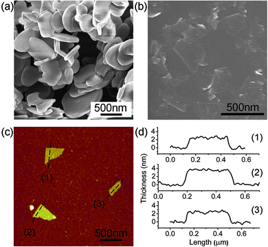 | ||
| Fig. 1 (a) SEM image of the initial hBN particles; (b) SEM image of BN nanosheets mechanically exfoliated by ball milling; (c) AFM image of three BN sheets on a Si substrate; and (d) the height trace curves indicating their thicknesses of 2.3, 2.4 and 3.7 nm and sizes of several hundred nanometres. | ||
The TEM image in Fig. 2a shows a BN nanosheet of ∼250 nm, along with a group of overlapping smaller sheets (upper part). The relatively straight edges of the big sheet indicate that it has mainly experienced tearing rather than vertical impact on the in-plane surface during ball milling, resulting in no major destructions of the crystal structure.19,24 The observed curled edge (lower part) is usually found on ultrathin graphite sheets or graphene, as curling can reduce the free surface and dangling bond energies.28,29 A typical electron diffraction (ED) pattern of the milled sheets is shown in Fig. 2b. This pattern, with the presence of several sets of dots with six-fold symmetry, has contributions from several sheets. A high-resolution TEM image (Fig. 2c) confirms the highly crystalline structure of the milled sheets. The distance between the adjacent white dots in Fig. 2c is ∼0.25 nm, estimated from the intensity profile. This distance is that between the centres of two adjacent hexagonal rings or the lattice spacing of hBN (Fig. 2d).19,30 Accordingly, the calculated distance between the nearest B and N atoms is ∼0.144 nm. Fig. 2e and f show three sheets with ∼3, ∼4 and ∼5 BN layers. The edges of a total of 22 sheets investigated by TEM were all less than 4 nm thick or fewer than 10 in layer number (Fig. 2g).
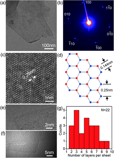 | ||
| Fig. 2 (a) TEM image of the BN sheets; (b) a typical electron diffraction pattern from several milled sheets; (c) HRTEM of a sheet; (d) a representative crystal structure of the basal plane of hBN; (e) and (f) TEM images of three sheets with 3, 4 and 5 layers of BN; and (g) statistics of the number of layers for 22 sheets. | ||
The quality or density of local defects of the nanosheets, i.e. point defects, possibly caused by ball milling was analyzed using NEXAFS spectroscopy. Fig. 3 compares the NEXAFS spectra, of the B K-edge in the π* resonance region, of the initial hBN particles and the 15 h milled sheets. Both spectra show typical character of hBN with a dominant peak at ∼192 eV and three weak peaks at 192.6, 193.3 and 194.1 eV. The 192 eV peak corresponds to the B 1s–π* transition characteristics of the p-type bonding between layers of hBN with each B atom bonded to three N atoms in a planar configuration.31,32 The strong 192 eV peak indicates that the milled sheets are still predominantly of hexagonal boron nitride structure. There is no noticeable broadening of the 192 eV peak for the milled sheets, suggesting no dramatic increase in disordered structures or carbon bonds. The three small peaks located at higher energies can be attributed to nitrogen vacancies or the decoration of nitrogen vacancies by oxygen atoms.32,33 In general, the intensity of these peaks is related to the level of defects in the material. Therefore, the observed small increase in the intensities of these peaks suggests only slightly more point defects or local impurities after milling, such as oxygen, which may be due to the oxygen absorption on the newly created dangling bonds on the edge of the sheets when exposed to air.33 The NEXAFS results indicate that the milling under the low-energy conditions used had little damage to the in-plane structure.
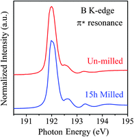 | ||
| Fig. 3 The NEXAFS spectra of the un-milled hBN particles and the 15 h milled nanosheets in the region of B K-edge near the π* resonance. | ||
XRD was used to investigate the peeling of the hBN particles with different ball milling times (Fig. 4a). For this reason, the samples directly taken from the milling vial were used without centrifugation treatment. The XRD spectra of the un-milled powder and the 2 h and 25 h milled samples are compared in Fig. 4b to see the changes in peak intensity. It can be seen that after 2 h and 25 h of ball milling, the intensities of the (004) and (006) peaks had only slightly decreased. The (004) peak still existed after 25 h of milling and the (006) peak was present until 15 h of milling. These indicate that the milling did not greatly influence the short range order of the BN crystals in the c-direction.34 In other words, the in-plane layers were little affected under the tailored milling conditions, in agreement with the NEXAFS results. The (100), (101), (102), (110) and (112) peaks, in contrast, almost disappeared after 2 h milling. As the short range order of the crystals was mostly intact, the disappearance of these peaks should be caused by the preferential orientation of the milled BN sheets into substrates with the (002) basal plane parallel to the substrate surface, due to both the reduced thickness and the large diameter to thickness ratio of the milled sheets. This preferential orientation was not observed on the un-milled hBN particles (Fig. 1a), but clearly shown on the nanosheets (Fig. 1b and 2a). Overall, according to XRD, the most efficient exfoliation happened in the first several hours of milling and most particles were cleaved into thin sheets within 15 h.
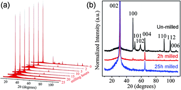 | ||
| Fig. 4 (a) Normalized XRD spectra of the initial hBN particles and the sheets ball milled for different times without centrifugation; (b) the enlarged XRD spectra of the un-milled and 2 h and 25 h ball milled samples. | ||
Efficient mechanical cleavage while retaining the in-plane crystal structure can only be achieved under the following selected milling conditions. First, a suitable type of ball mill needs to be chosen. Most types of high-energy ball mills employ strong collisions or vertical impacts to fracture particles and even destroy crystalline structures to amorphous or non-equilibrium phases.12,14,35 A planetary mill, on the other hand, allows to control balls in rolling actions that apply only shear force on the milling materials. Second, the use of small steel balls also helped to minimize the damage to the in-plane crystal structure and the relatively large number of these balls makes the milling more efficient. Third, a liquid controlling agent is essential in milling as it acts as a lubricant to make the shear force much gentler to further reduce the damage to the structures and also to prevent the welding effect.9,36 Under the gentle shear force, preferential cleavage happens mainly along the weak inter-plane bonds so that the thin BN layers were able to be mechanically peeled off from the hBN particles. Fig. 5 illustrates how the cleavage happens during milling by showing two intermediate stages. The laminated thin sheets peeling off the edge of an hBN particle (Fig. 5a) is likely to be caused by a milling ball colliding with the edge of the particle and then sliding over it (Fig. 5b). Sheets as thin as ten nanometres and exfoliated from the top of another particle (Fig. 5c) should be due to a ball rolling over the top surface of the particle which created a strong shear force (Fig. 5d).
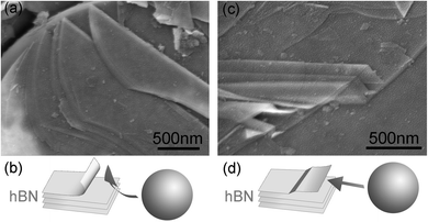 | ||
| Fig. 5 SEM images and corresponding diagrams illustrating two observed exfoliating mechanisms under the shear force created by milling balls: (a), (b) cleavage from the edge of an hBN particle; (c), (d) thin sheets peeling off the top surface of an hBN particle. | ||
Comparing other milling agents, i.e.water, ethanol and dodecane, benzyl benzoate gave the best peeling results because of the high viscosity of benzyl benzoate and its similar surface tension to hBN,37,38 which prevents the newly peeled-off BN sheets from agglomerating and also enhances exfoliation. Another advantage of benzyl benzoate is that it was found to greatly reduce the amount of steel contamination coming from the milling vial and balls. The Fe content in the 30 h benzyl benzoate milled hBN is only 0.26 at%, which is much less than those using dry milling, water (12.71 at% Fe), ethanol (8.95 at% Fe) or dodecane (1.17 at% Fe). This is due to both the higher viscosity of benzyl benzoate which is more effective at reducing the ball impacts and the lower reactivity of benzyl benzoate (an aromatic compound) with Fe than the other three solvents (dodecane has a more reactive straight chain structure). It has been previously reported that sonication in a liquid with a similar surface tension to graphite and hBN can also have quite good exfoliation effect,19,20,38 but ball milling is believed to be the main reason for the observed large scale cleavages. Compared to the previously reported solution exfoliation of BN,19–21 a much shorter sonication time was used, which was not enough for the observed exfoliation without milling treatment (see ESI†). Besides, when water and ethanol were used during milling and sonication, roughly similar exfoliation results can be achieved. It should be emphasized that, similar to the liquid exfoliation method,39 this low-energy ball milling method can be used to produce nanosheets from any layered materials.
Conclusions
Ball milling has been shown to be an effective and efficient way to mechanically cleave nanosheets under suitable milling conditions. After centrifugation, BN nanosheets with diameters of hundreds of nanometres and thicknesses of a few nanometres were harvested. In spite of the thickness reduction, the ball milling produced little damage to the in-planar structure and introduced a very small amount of point defects or impurities. This milling method is not only easily scalable but also applicable to other layered materials for producing nanosheets. It will definitely enhance the large scale application of 2D nanomaterials.Acknowledgements
L. H. Li thanks Peter Lamb and Gigi George of Deakin University for helpful discussions. We gratefully acknowledge financial support from the Australian Synchrotron Research Program and the Centre of Excellence awards from Australian Research Council.Notes and references
- K. S. Novoselov, A. K. Geim, S. V. Morozov, D. Jiang, M. I. Katsnelson, I. V. Grigorieva, S. V. Dubonos and A. A. Firsov, Nature, 2005, 438, 197 CrossRef.
- Y. B. Zhang, Y. W. Tan, H. L. Stormer and P. Kim, Nature, 2005, 438, 201 CrossRef CAS.
- H. B. Zeng, C. Y. Zhi, Z. H. Zhang, X. L. Wei, X. B. Wang, W. L. Guo, Y. Bando and D. Golberg, Nano Lett., 2010, 10, 5049 CrossRef CAS.
- C. Lee, X. D. Wei, J. W. Kysar and J. Hone, Science, 2008, 321, 385 CrossRef CAS.
- A. A. Balandin, S. Ghosh, W. Z. Bao, I. Calizo, D. Teweldebrhan, F. Miao and C. N. Lau, Nano Lett., 2008, 8, 902 CrossRef CAS.
- K. S. Novoselov, A. K. Geim, S. V. Morozov, D. Jiang, Y. Zhang, S. V. Dubonos, I. V. Grigorieva and A. A. Firsov, Science, 2004, 306, 666 CrossRef CAS.
- D. Pacile, J. C. Meyer, C. O. Girit and A. Zettl, Appl. Phys. Lett., 2008, 92, 133107 CrossRef.
- C. Lee, Q. Y. Li, W. Kalb, X. Z. Liu, H. Berger, R. W. Carpick and J. Hone, Science, 2010, 328, 76 CrossRef CAS.
- R. Janot and D. Guerard, Carbon, 2002, 40, 2887 CrossRef CAS.
- M. V. Antisari, A. Montone, N. Jovic, E. Piscopiello, C. Alvani and L. Pilloni, Scr. Mater., 2006, 55, 1047 CrossRef CAS.
- W. F. Zhao, M. Fang, F. R. Wu, H. Wu, L. W. Wang and G. H. Chen, J. Mater. Chem., 2010, 20, 5817 RSC.
- T. D. Shen, W. Q. Ge, K. Y. Wang, M. X. Quan, J. T. Wang, W. D. Wei and C. C. Koch, Nanostruct. Mater., 1996, 7, 393 CrossRef CAS.
- Y. Chen, J. D. Fitz Gerald, L. T. Chadderton and L. Chaffron, Appl. Phys. Lett., 1999, 74, 2782 CrossRef CAS.
- Y. Chen, J. D. Fitz Gerald, J. S. Williams and S. Bulcock, Chem. Phys. Lett., 1999, 299, 260 CrossRef CAS.
- L. H. Li, Y. Chen and A. M. Glushenkov, Nanotechnology, 2010, 21, 105601 CrossRef.
- L. Song, L. Ci, H. Lu, P. B. Sorokin, C. Jin, J. Ni, A. G. Kvashnin, D. G. Kvashnin, J. Lou, B. I. Yakobson and P. M. Ajayan, Nano Lett., 2010, 10, 3209 CrossRef CAS.
- A. Nag, K. Raidongia, K. P. S. S. Hembram, R. Datta, U. V. Waghmare and C. N. R. Rao, ACS Nano, 2010, 4, 1539 CrossRef CAS.
- W. Q. Han, L. J. Wu, Y. M. Zhu, K. Watanabe and T. Taniguchi, Appl. Phys. Lett., 2008, 93, 223103 CrossRef.
- C. Y. Zhi, Y. Bando, C. C. Tang, H. Kuwahara and D. Golberg, Adv. Mater., 2009, 21, 2889 CrossRef CAS.
- J. H. Warner, M. H. Rummeli, A. Bachmatiuk and B. Buchner, ACS Nano, 2010, 4, 1299 CrossRef CAS.
- Y. Lin, T. V. Williams, T.-B. Xu, W. Cao, H. E. Elsayed-Ali and J. W. Connell, J. Phys. Chem. C, 2011, 115, 2679 CrossRef CAS.
- Y. Lin, T. V. Williams and J. W. Connell, J. Phys. Chem. Lett., 2010, 1, 277 Search PubMed.
- S. Stankovich, D. A. Dikin, G. H. B. Dommett, K. M. Kohlhaas, E. J. Zimney, E. A. Stach, R. D. Piner, S. T. Nguyen and R. S. Ruoff, Nature, 2006, 442, 282 CrossRef CAS.
- V. C. Tung, M. J. Allen, Y. Yang and R. B. Kaner, Nat. Nanotechnol., 2009, 4, 25 CrossRef CAS.
- X. L. Li, G. Y. Zhang, X. D. Bai, X. M. Sun, X. R. Wang, E. Wang and H. J. Dai, Nat. Nanotechnol., 2008, 3, 538 CrossRef CAS.
- N. Alem, R. Erni, C. Kisielowski, M. D. Rossell, W. Gannett and A. Zettl, Phys. Rev. B: Condens. Matter Mater. Phys., 2009, 80, 155425 CrossRef.
- C. Suryanarayana, Prog. Mater. Sci., 2001, 46, 1 CrossRef CAS.
- L. M. Viculis, J. J. Mack and R. B. Kaner, Science, 2003, 299, 1361 CrossRef CAS.
- T. J. Booth, P. Blake, R. R. Nair, D. Jiang, E. W. Hill, U. Bangert, A. Bleloch, M. Gass, K. S. Novoselov, M. I. Katsnelson and A. K. Geim, Nano Lett., 2008, 8, 2442 CrossRef CAS.
- D. Golberg, Y. Bando, M. Eremets, K. Kurashima, T. Tamiya, K. Takemura and H. Yusa, J. Electron Microsc., 1997, 46, 281 CAS.
- B. M. Davies, F. Bassani, F. C. Brown and C. G. Olson, Phys. Rev. B: Condens. Matter Mater. Phys., 1981, 24, 3537 CrossRef CAS.
- A. Bozanic, M. Petravic, L. J. Fan, Y. W. Yang and Y. Chen, Chem. Phys. Lett., 2009, 472, 190 CrossRef CAS.
- M. Petravic, R. Peter, I. Kavre, L. H. Li, Y. Chen, L. J. Fan and Y. W. Yang, Phys. Chem. Chem. Phys., 2010, 12, 15349 RSC.
- H. Hermann, T. Schubert, W. Gruner and N. Mattern, Nanostruct. Mater., 1997, 8, 215 CrossRef CAS.
- N. J. Welham, V. Berbenni and P. G. Chapman, J. Alloys Compd., 2003, 349, 255 CrossRef CAS.
- F. SalverDisma, C. Lenain, B. Beaudoin, L. Aymard and J. M. Tarascon, Solid State Ionics, 1997, 98, 145 CrossRef CAS.
- N. Rathod and S. G. Hatzikiriakos, Polym. Eng. Sci., 2004, 44, 1543 CrossRef CAS.
- Y. Hernandez, V. Nicolosi, M. Lotya, F. M. Blighe, Z. Sun, S. De, I. T. McGovern, B. Holland, M. Byrne, Y. K. Gun'Ko, J. J. Boland, P. Niraj, G. Duesberg, S. Krishnamurthy, R. Goodhue, J. Hutchison, V. Scardaci, A. C. Ferrari and J. N. Coleman, Nat. Nanotechnol., 2008, 3, 563 CrossRef CAS.
- J. N. Coleman, M. Lotya, A. O'Neill, S. D. Bergin, P. J. King, U. Khan, K. Young, A. Gaucher, S. De, R. J. Smith, I. V. Shvets, S. K. Arora, G. Stanton, H. Y. Kim, K. Lee, G. T. Kim, G. S. Duesberg, T. Hallam, J. J. Boland, J. J. Wang, J. F. Donegan, J. C. Grunlan, G. Moriarty, A. Shmeliov, R. J. Nicholls, J. M. Perkins, E. M. Grieveson, K. Theuwissen, D. W. McComb, P. D. Nellist and V. Nicolosi, Science, 2011, 331, 568 CrossRef CAS.
Footnote |
| † Electronic supplementary information (ESI) available: HeIM images of the initial hBN particles and BN sheets produced by ball milling, TEM studies of the initial hBN particles, yield estimation method, exfoliation effect solely from sonication and results from dry milling. See DOI: 10.1039/c1jm11192b |
| This journal is © The Royal Society of Chemistry 2011 |
