Nanostructured silicon for high capacity lithium battery anodes†
Jeannine R.
Szczech
* and
Song
Jin
*
Department of Chemistry, University of Wisconsin—Madison, 1101 University Avenue, Madison, Wisconsin 53706, USA. E-mail: szczech@chem.wisc.edu; jin@chem.wisc.edu; Web: jin.chem.wisc.edu
First published on 16th November 2010
Abstract
Nanostructured silicon is promising for high capacity anodes in lithium batteries. The specific capacity of silicon is an order of magnitude higher than that of conventional graphite anodes, but the large volume change of silicon during lithiation and delithiation and the resulting poor cyclability has prevented its commercial application. This challenge could potentially be overcome by silicon nanostructures that can provide facile strain relaxation to prevent electrode pulverization, maintain effective electrical contact, and have the additional benefits of short lithium diffusion distances and enhanced mass transport. In this review, we present an overview of rechargeable lithium batteries and the challenges and opportunities for silicon anodes, then survey the performance of various morphologies of nanostructured silicon (thin film, nanowires/nanotubes, nanoparticles, and mesoporous materials) and their nanocomposites. Other factors that affect the performance of nanostructured silicon anodes, including solvent composition, additives, binders, and substrates, are also examined. Finally, we summarize the key lessons from the successes so far and offer perspectives and future challenges to enable the applications of silicon nanoanodes in practical lithium batteries at large scale.
 Jeannine R. Szczech | Jeannine Szczech studied chemistry at the University of WI—Madison, graduating with a B.S. degree in 2005. She remained at the UW—Madison to continue her studies in the Song Jin research group, earning a Ph.D. in Materials Chemistry in 2010. Her research interests include nanoscale materials with applications in thermoelectric and electrochemical devices. |
 Song Jin | Song Jin received his B.S. from Peking University in 1997 and his Ph.D. from Cornell University in 2002. He has been at the University of Wisconsin-Madison since 2004 and is currently an associate professor of chemistry. He is interested in the chemistry and physics of nanomaterials. Dr Jin studies the fundamental formation mechanisms of nanowires, their novel physical properties, and applications in renewable energy such as photovoltaic and thermoelectric energy conversion, and energy storage. |
Broader contextRechargeable lithium batteries have become the ubiquitous power source for portable electronics such as cell phones and laptop computers. They may soon find widespread usage in hybrid and electric vehicles and become an important part of the energy storage solutions in renewable energy technologies. To meet the ever increasing power requirements of these applications, new electrode materials are needed to increase the energy density beyond currently available lithium batteries. Although silicon anode materials are known to have high lithium storage capacity, they cannot be used in their bulk form due to the extreme structural degradation that occurs during use. This challenge may be overcome by utilizing nanostructures, such as thin films, nanowires or nanotubes, and nanoparticles, which are more resistant to structural degradation by virtue of their small nanoscale sizes. In this review, we survey the impressive progresses recently made in this active research area, describe the pressing issues currently facing nanostructured silicon electrodes, and discuss how these challenges may be overcome. |
1. Introduction
Lithium ion secondary batteries are attractive energy storage devices with high gravimetric and volumetric capacity and the ability to deliver high rates of power.1–9 They have become ubiquitous power sources for mobile applications such as personal electronics and laptop computers, but current lithium battery technology cannot meet the ever increasing power requirements for applications such as electric and hybrid electric vehicles and power storage to accommodate the intermittent nature of certain renewable energy sources. This has spurred intense interest in developing high gravimetric and volumetric capacity battery electrodes to surpass the energy density of the current generation of lithium batteries. Significant research challenges and opportunities exist for all aspects of battery materials:2,5 cathode, anode, electrolyte, and separators. We will focus on the anode materials in this discussion.Based on energy density considerations, lithium metal is the best anode material. However, the electroplating of dendritic lithium during charging can lead to short circuit, posing severe safety concerns for lithium metal anodes. The most frequently used material for commercial secondary lithium ion battery anodes is graphite, in which a maximum of one lithium can intercalate for every six carbon atoms.10 The volumetric expansion during lithium intercalation between the planar graphite layers is just over 10%, resulting in high reversibility and stable capacity over repeated cycling.11 Nonetheless, the theoretical capacity of graphite (372 mAhg−1) is low compared to other possible anode materials, such as the lithium alloys of silicon or tin, limiting the power density. Development of high capacity anodes capable of sustaining high power rates is therefore necessary.
Silicon is a promising high capacity alternative to graphite anodes. It has a low discharge potential (∼ 370 mV vs. Li/Li+),12 which makes it suitable for high-power applications when paired with common cathode materials such as LiCoO2 or LiMn2O4. It is abundant and non-toxic, and can be alloyed with up to 4.4 lithium atoms per silicon atom to create an alloy with high electrochemical capacity.13 The theoretical capacity of the fully lithiated alloy Li4.4Si is 4212 mAhg−1, an order of magnitude higher than graphite. Similar to graphite, silicon exhibits a long plateau over much of its discharge curve, providing a stable voltage during cycling, and silicon does not suffer from solvent co-intercalation, presenting an additional advantage over graphite.14
However, the commercial use of silicon in lithium cells has been limited by the low cycling stability of bulk silicon. The large volume change (> 300%)15 during lithiation leads to high internal stress, electrode pulverization and subsequent loss of electrical contact between the active material and current collector, leading to poor reversibility and rapidly declining capacity. Moving from bulk to nanoscale morphologies has the potential to solve this limitation by managing the large stresses associated with the expansion and contraction of alloy anodes during electrochemical alloying. This potential is being explored by academic and commercial researchers alike; in recent years, the number of patents granted for Si or Si-based composite electrodes with nanostructured morphologies has increased markedly.16–29
A number of nanoscale morphologies have been investigated to minimize electrode pulverization and capacity loss in silicon anodes, including thin films,13,30–53nanowires and nanotubes,54–67 and nanoparticles.61,68–114 These morphologies improve cycling stability by minimizing the total volumetric expansion, incorporating pores or voids to accommodate expansion, or by exploiting high surface-to-volume ratios to manage material stress.57 Nanostructured materials also offer other benefits, including short lithium diffusion distances within the electrode, high rate capability due to the large surface area, and enhanced diffusion along surfaces and grain boundaries.
Nanostructured silicon anodes face some important challenges as well. High surface-to-volume ratios can facilitate efficient transfer of lithium from the solvent to the active material to achieve high rates, but the potential for uncontrolled reaction and thermal runaway is greater for high surface area electrodes. Although there have not yet been reports in the literature to suggest thermal runaway in nanostructured silicon anodes poses a serious problem, morphological optimization to achieve a balance between high rates and safety is needed. The high surface area of nanostructured electrodes may also present a challenge for limiting irreversible capacity (the difference between the charge and discharge capacity) caused by formation of a passivation layer, or solid electrolyte interface (SEI) layer, on the electrode surface. High irreversible capacities have been reported for silicon anodes, thus the formation of a stable self-limiting SEI layer is expected to be a formidable challenge.
In this review, we will first present a broad overview of secondary (rechargeable) lithium batteries and explain the basic operation of a secondary lithium battery. Then we will detail the advantages of using nanostructured silicon as the anode and the challenges that must be overcome before it can be used as the anode in a practical cell. A survey of recent work in this area will follow, and additional factors that can negatively impact electrode performance will be presented. Unless otherwise noted, all cycling capacities discussed herein are reported as the specific delithiation capacity of the active material (either pure Si or a Si-based nanocomposite).
2. Lithium battery operation and challenges for silicon anodes
Lithium batteries consist of one or more electrochemical cells connected in parallel or in series to obtain the desired current and voltage characteristics, comprised of a positive electrode (the cathode) and a negative electrode (the anode), which are separated from one another by a lithium ion permeable membrane, and an electrolyte that conducts lithium ions. Fig. 1 shows a schematic of a lithium battery with a silicon anode and a lithium metal oxide (LiMxOy) intercalation cathode. The anode and cathode are connected through an external circuit. During charging (Fig. 1a), electrons driven by an external power source flow from the cathode (LiMxOy) through the external circuit to the anode (silicon), while lithium ions deintercalate from the cathode and move through the electrolyte to the anode to maintain charge neutrality. As lithium ions are alloyed with silicon, the anode expands until it has reached the desired state of charge. Discharging is simply the reverse of this process (Fig. 1b). The anode undergoes volume contraction as lithium ions are liberated. The ions shuttle back through the electrolyte and undergo insertion at the cathode, while electrons move towards the cathode through the external circuit, performing useful work in the process. | ||
| Fig. 1 Schematic of a lithium battery containing a silicon anode and lithium metal oxide cathode during a) charging and b) discharging. | ||
The open circuit voltage (VOC) represents the voltage between the two terminals when a load is not connected and is proportional to the difference between the cathode and anode electrochemical potentials  , where F is the Faraday constant. VOC is typically close to 3–4 V in lithium cells.
2.1 Electrolytes and SEI formation
A mixture of aprotic organic solvents is typically used in commercial lithium batteries, including cyclic and linear alkyl carbonates such as ethylene carbonate (EC), dimethyl carbonate (DMC), diethyl carbonate (DEC), ethyl methyl carbonate (EMC), and propylene carbonate (PC). The solvent composition is chosen to achieve a balance between viscosity, the ability of the solvent to form a stable passivation layer, and sufficiently high dielectric constant to dissolve lithium salts such as lithium hexafluorophosphate (LiPF6) or lithium perchlorate (LiClO4). The operating potential of the anode in lithium cells is close to the potential of metallic lithium, which lies outside of the thermodynamic stability region of organic electrolytes. Hence, the electrolyte solution undergoes electrochemical decomposition resulting in the formation of a passivating SEI layer, which inhibits electron transfer between the electrolyte and electrode, and provides kinetic stability outside of the solvent potential window.115Well-formed SEI layers are impermeable to the solvent, but allow migration of lithium ions between the solvent and active material. The SEI layer is thus self-limiting when electrode expansion is minimized. Nonetheless, exposure of fresh active material from electrode expansion during cycling encourages continual SEI growth and irreversible capacity loss. This is a difficult challenge to overcome in intermetallic alloy anodes, because the SEI layer does not undergo a similar expansion and cracking of the SEI layer can be severe.97 To minimize capacity loss, a uniform SEI layer should form during the first charge cycle and heal quickly from any cracking that may occur from expansion mismatches during lithiation/delithiation.116
The composition of the SEI layer, which contains electrolyte decomposition products in addition to products from side reactions between the electrolyte and active material, is important because it influences the kinetics of lithium ion transfer between the electrolyte and the electrode and thus the achievable rate of charge and discharge. If the SEI layer hinders mass transport, electrode polarization will increase, lowering the power density. The SEI layer on silicon electrodes in alkyl carbonate electrolytes typically consists of a heterogeneous mosaic of compounds including poly(ethylene) oxides (-[CH2-CH2-O]n-) (PEO), lithium alkyl carbonates (ROCO2Li), lithium alkoxides (ROLi), lithium carbonate (Li2CO3), lithium oxide (Li2O), and lithium fluoride (LiF), in addition to fluorinated carbon or silicon species.50,78,117,118 The composition differs slightly on silicon electrodes coated with carbon, to instead contain primarily siloxanes (-[SiORR′]n-), PEOs, ROCO2Li, ROLi, Li2CO3, and LiF.78
2.2 Challenges for silicon anodes
Unlike intercalation electrodes, such as graphite anodes and LiMxOy cathodes, intermetallic alloy electrodes experience large volume changes during lithiation and delithiation and may go through multiple crystallographic phase transitions, which shortens the cycle life and contributes to cell failure. According to the Li-Si phase diagram, four crystalline Li-Si phases exist: Li12Si7, Li7Si3, Li13Si4, and Li22Si5.119 Peaks in the polarization curve during lithiation of silicon are frequently assigned to these phases, and some evidence exists to indicate these phases may be formed during electrochemical cycling.66,120 In many cases, a single long voltage plateau is observed near 100 mV (vs. Li/Li+) during cathodic polarization, suggesting continual lithiation of an amorphous alloy rather than sequential formation of distinct lithium silicide phases.121–123 When silicon electrodes are charged to below 50 mV (vs. Li/Li+), a peak in the differential capacity curve due to the formation of a crystalline Li15Si4 phase has been reported.124In many cases, the initial charge capacity of both pure silicon and silicon composite anodes is near the theoretical capacity. An irreversible capacity loss due to SEI formation is seen in the first cycle, followed by more stable cycling with little capacity fade if mechanical fracture of the electrode can be avoided. Irreversible capacity loss is clearly tied to the degree of expansion during lithiation. Electrode pulverization during cycling can cause lithium trapping in the active material, loss of electrical contact, and progressive consumption of active material resulting from continual electrolyte exposure during expansion and contraction during cycling, all of which contribute to low Coulombic efficiency.
The crystallinity of pristine silicon anodes changes markedly after a single charge/discharge cycle. During the first lithiation cycle, crystalline silicon undergoes a phase transition to produce an amorphous alloy.125 Because amorphous materials experience isotropic material stress during volumetric changes, formation of an amorphous phase is beneficial for reducing the risk of stress fracture during electrochemical alloying. Therefore, by limiting the upper and lower voltage cut-offs, the amorphous-to-crystalline transitions can be avoided, increasing the reversibility and capacity of alloy electrodes.122–124 The depth of charge/discharge can additionally be controlled to limit the degree of lithiation and volumetric growth and thus mitigate electrode pulverization and delamination. These tactics have been successful in extending the cycle life of intermetallic alloy anodes, but comes at the cost of limiting the capacity. The use of inactive matrixes to buffer volume expansion and adding conductive additives can enhance cycling stability, but the presence of inactive material also decreases the energy density. Nevertheless, lowering the capacity to improve reversibility and cycle lifetime may be an acceptable trade-off, since it is the total battery capacity rather than the capacity of the anode alone that determines the energy density of the battery. The cell specific capacity (neglecting the weight contribution of the inactive components of the battery) can be calculated1 based on the specific capacity of the anode and cathode materials. The effect of anode capacity on energy density is illustrated in Fig. 2, which shows the theoretical capacity of a hypothetical cell comprised of a Si anode and LiCoO2 cathode (the theoretical capacity of LiCoO2 is 147 mAhg−1) based on only the active anode and cathode materials. The cell specific capacity increases as the anode specific capacity increases until the latter reaches about 2000 mAhg−1, after which cell capacity gains from further increasing the anode capacity level off. Thus, in the absence of significant improvement in cathode capacity, limiting the anode capacity to improve cycle life and stability will not appreciably reduce overall cell capacity.
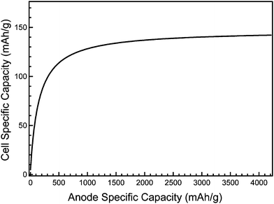 | ||
| Fig. 2 Theoretical cell specific capacity as a function of the anode specific capacity, considering only the active silicon (anode) and LiCoO2 (cathode) masses. | ||
3. Advantages of nanostructured or nanoscale electrodes
Nanostructured or nanoscale electrodes can be engineered with morphologies such as nanowire arrays or ordered mesoporous structures to provide the necessary volume of free space to accommodate expansion during alloying, thus minimizing material stress and electrode pulverization to achieve greater reversibility and cycling stability.4,7–9 The nature of the stress experienced by the active material during lithiation/delithiation is seen to depend on morphology. Thin silicon films, which can have strong adhesion to the substrate, have been shown to undergo anisotropic volume changes.30,36 Particles, on the other hand, are not constrained by substrate adhesion and therefore expand isotropically.108Nanoscale dimensions allow quick relaxation of stress, making nanoparticles more resistant to fracture than bulk particles. Comparison of the calculated misfit stress energy in partially delithiated particles (consisting of a lithiated core and delithiated shell) suggests fracture should not occur during cycling for particles having diameters of 10 nm or less.126 Other calculations focusing on the Li-Sn system, which undergoes a similar volume expansion during electrochemical alloying, suggest that particles with diameters less than 200 nm will resist fracture.127 Indeed, a reduction in particle diameter is correlated with an increase in cycling stability. For example, LixSn alloys with particle diameters ranging from 200–400 nm have been shown to resist fracture and demonstrate improved Coulombic efficiency compared to larger micron sized particles.88 Because both silicon and tin experience similar volumetric changes during lithiation, it can be expected that comparable improvements are possible for nanocrystalline Si anodes.
The use of nanoscale morphologies may also enhance the rate capability and specific capacity. As expected, the capacity of silicon electrodes decreases at high charge/discharge rates, due to low lithium ionic conductivity in silicon and sluggish mass transfer at the electrode interface.5 By reducing electrode dimensionality to increase the surface-to-volume ratio and provide shorter lithium diffusion distances, electrode polarization may be reduced, allowing high capacities to be realized. For emerging high capacity mobile energy storage applications (such as in plug-in electrical vehicles), the volumetric capacity is increasingly more important than the gravimetric capacity, as space is at premium when the total power demand is high. However, it is difficult to determine typical volumetric capacities of reported nanostructured silicon anodes, as so far very few published reports clearly state the volumetric capacity, instead favoring gravimetric capacity. To fully evaluate the potential advantages of nanostructured silicon anodes over conventional graphite in mobile applications, it will be useful to closely examine this metrics for comparison.
The capacity, reversibility, and cycling life can vary widely between nanostructured or nanoscale silicon anodes with similar morphology and particle size. These differences likely result from differences in reported synthesis; binder, additive and electrolyte composition; the ratio of active material, conductive additives and binder; processing parameters such as vacuum drying, annealing, and hydraulic pressing; and the depth of charge/discharge, voltage cut-offs, and charge/discharge rates during cycling. The wide variation in electrochemical performance reported for a given morphology makes it difficult to categorically state that any particular morphology is superior; hence, the focus of the survey section will be on general trends that emerge, along with some representative data.
3.1 Nanostructure morphologies—thin films
Thin silicon films have demonstrated the highest capacities and longest cycle lives due to the small amount of active material limiting total volumetric expansion. The performance of thin films improves as film thickness decreases, consistent with the Griffith-Irwin relation, which states that the critical fracture stress increases as film thickness decreases:126,127 | (1) |
The volumetric expansion during lithiation of thin films has been shown to occur anisotropically, with expansion occurring perpendicular to the film surface.30 On the other hand, contraction during delithiation occurs both perpendicular to and in plane with the substrate, leading to cracking of the film after the first discharge cycle. Scanning electron and optical microscope observation of electrochemically cycled thin films reveals that the cracked films, which form islands resembling mudflats, remain attached to the substrate after delithiation.30,32Fig. 3 shows the morphology of a thin silicon film after lithiation and delithiation.30 The copper substrate is visible through the larger cracks, and many smaller cracks can be seen in the film. Following the initial fracture, the active material can be cycled without additional film cracking, and in optimized anodes capacity loss after the first cycle is limited because electrical contact between the active material and the current collector is maintained.
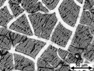 | ||
| Fig. 3 Optical micrograph of a cracked thin silicon film after lithiation and delithiation. Reproduced from Ref. 30 by permission of the Electrochemical Society. | ||
The main limitation of thin film electrodes derives from the small mass of active material and the resultant low cell capacity. Nonetheless, silicon thin film anodes have demonstrated that high capacities using silicon anodes are possible if we can manage material stress during cycling.
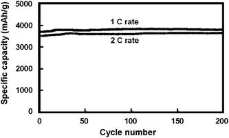 | ||
| Fig. 4 Specific capacity of a 50 nm thick amorphous silicon electrode at 1C and 2C rates. Reproduced from Ref. 13 by permission from Elsevier. | ||
Silicon anode capacities sometimes increase over the first few cycles before a stable capacity is maintained. Such increasing capacity during initial cycling has been reported to result from ‘activation’ of crystalline silicon as it becomes amorphous during cycling, because higher lithium mobility in amorphous silicon allows lithium insertion into larger portions of the electrode as cycling progresses.54 In the above case, the films were amorphous prior to cycling, suggesting additional causes exist. An additional cause of activation may derive from enhanced diffusion known to occur in nanocrystalline solids as a consequence of the high density of grain boundaries. If micro-cracking occurs during the initial cycles to form new internal surfaces that are not exposed to the electrolyte and therefore do not increase irreversible reactions, enhanced lithium diffusion along the crack surfaces may occur, reducing polarization. By the Griffith-Irwin relation, the active material is predicted to become resistant to further cracking after a sufficient crack density has been achieved (i.e. the grains become sufficiently small), thus resulting in a leveling-off of material activation after a few charge/discharge cycles.
Intrinsic silicon films exhibited lower reversible capacities, as seen in a 50 nm intrinsic silicon film that had a reversible capacity near 1850 mAhg−1 after 5 cycles,13 suggesting that dopant concentrations must play an important role in improving capacity and stability. Enhanced reversibility and capacity in doped electrodes has been reported in carbon-based electrodes with substitutional boron or phosphorus doping, due to an increase in the interlayer spacing with dopant substitution to permit more facile lithium insertion.129–131 In the case of alloy anodes, it is not expected that doping would increase reversibility via a similar mechanism, because low concentrations of dopants will not alter the degree of volumetric expansion appreciably. It is clear there must be an alternative explanation for enhanced performance in doped silicon anodes. The high capacities seen in the n-type films compared to intrinsic silicon may arise from reduced ohmic polarization or more uniform alloying of the anode during cycling. Since unlithiated intrinsic silicon is a rather poor electrical conductor, it may be more favorable to further lithiate regions containing the lower lithium alloys before fresh silicon is lithiated. If this is the case, large stress gradients resulting from localized expansion gradients could lead to fracture and lowered capacities. For doped silicon, higher electrical conductivity would be expected both before and after lithiation, which could encourage more uniform lithiation of the electrode and minimize stress gradients, providing more reversible cycling at higher capacities.
High initial capacities are possible for moderately thick silicon films, but the reversible capacity and cycling lifetime decreases with increasing films thickness. A survey of the literature reveals that the reversible capacities of silicon films up to 250 nm thick are typically near 3000 mAhg−1, and capacities between 1000–2500 mAhg−1 are reported for thicknesses higher than this. Radio frequency magnetron sputtered 250 nm thick amorphous silicon films demonstrated reversible capacity as high as 3800 mAhg−1 over 29 cycles, before a rapid decline was observed.31,32 In contrast, the reversible capacity of a 1 μm thick film could be maintained at 3000 mAhg−1 for only 13 cycles, followed by quick decline. The marked capacity fade began during lithiation for both electrodes, initiated by delamination of the film from the copper substrate, as verified by SEM examination of cycled anodes.
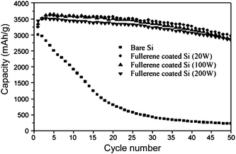
Silicon thin films have shown improved performance when the surface exposed to the electrolyte was coated with polymerized fullerenes to improve SEI layer formation.33 Reversible capacities as high as 3000 mAhg−1 were reported for 300 nm thick silicon films, higher than typically seen for uncoated films with comparable thickness. The degree of polymerization was controlled by varying the plasma power during plasma evaporation of the coating. Fig. 5 shows that the stabilizing effect of the fullerene layer increases as the degree of polymerization is increased. The capacity of uncoated thin films declines rapidly, before it stabilizes at a value lower than conventional graphite electrodes. The capacities of the fullerene-coated films declined more slowly, and all showed capacities between 2500–3000 mAhg−1 at the 50th cycle.
The cycling lifetime of thin SiMox alloy films with an average thickness of 4 μm increased as the molybdenum content increased.35 The uneven morphology of these films (Fig. 6a), which reflected the rough copper surface used as the current collector, may have contributed to the cycling stability of the films by allowing more isotropic expansion near the film's surface. The capacity of the films increased over the first 20 cycles, indicating activation of the films, then began to decline. Although the initial discharge capacity of the optimal composition SiMo0.79 was lower than that of a pure silicon film, the reversible capacity of the alloy was higher than the pure silicon film after 100 cycles, delivering 1180 mAhg−1 compared to 1000 mAhg−1 for silicon (Fig. 6b).
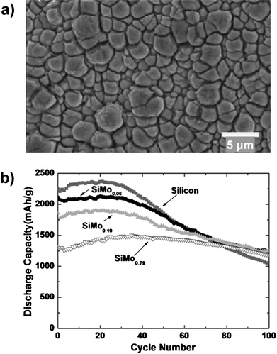 | ||
| Fig. 6 a) Plan-view SEM image of SiMo0.79 thin film after 50 cycles. b) Specific capacity of SiMox (0 ≤ x ≤ 0.79) thin film electrodes. Reproduced from Ref. 35 by permission of Elsevier. | ||
Although good reversibility and high capacities are possible using silicon and silicon composite films, the requirement to use extremely thin films to achieve reasonable cycling lifetimes hinders the commercial application of batteries using silicon thin film anodes, due to the low quantity of active material and the resulting low capacity and power density in thin films.
3.2 Nanostructure morphologies—nanowires and nanotubes
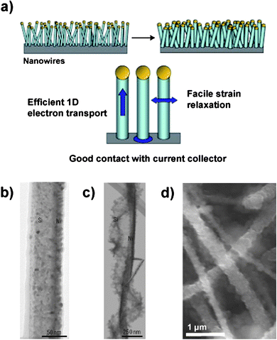 | ||
| Fig. 7 a) Schematic illustration of a silicon nanowire-based anode. The nanowires are deposited directly onto the current collector to provide a 1-D electron conduction pathway. b – c) TEM of a pristine Si nanowire partially coated with Ni b) before and c) after electrochemical cycling. d) SEM of Si nanowires after electrochemical cycling. Reproduced from Ref. 55 by permission of Nature Publishing Group. | ||
Because the surface-to-volume ratio is high for this morphology, the formation of a stable SEI layer is very important. Irreversible capacity losses as high as 38% in the first cycle have been reported in silicon nanowire-based anodes.59 The nanowire surfaces become rough during electrochemical cycling (Fig. 7b–7d) and porous structures resulting from slow diffusion of silicon atoms (the Kirkendall effect) have also been reported which could lead to significant SEI formation and increase the amount of active material consumed in irreversible reactions.55,56
The increase of electrode resistivity that accompanies the crystalline-to-amorphous transition can be minimized by utilizing crystalline/amorphous core/shell structures via partial lithiation of silicon nanostructures to create an amorphous shell on the crystalline nanowires.56 The lithiation of crystalline and amorphous silicon occur at approximately 120 and 200 mV (vs. Li/Li+), respectively, hence preferential lithiation of the amorphous shell can be carried out while preserving the higher conductivity crystalline core simply by controlling the potential during charging.56 Doping nanowires to increase their electrical conductivity has also been shown to improve capacity retention at high charge/discharge rates.66
Silicon nanotubes have demonstrated reversible capacities above 2600 and 2100 mAhg−1 over 50 cycles at rates of C/20 and C/5 respectively (Fig. 8).57Nanotubes undergo highly anisotropic expansion, exhibiting small (∼ 35%) axial expansion and markedly larger (∼ 120%) radial expansion. It has been proposed that the expansion anisotropy results from comparatively facile accommodation of expansion in the radial direction by the inner and outer free surfaces of the tube. Formation of an SEI layer on the inner surface of the nanotubes is believed to have been inhibited, although definitive evidence to support this has not been presented.
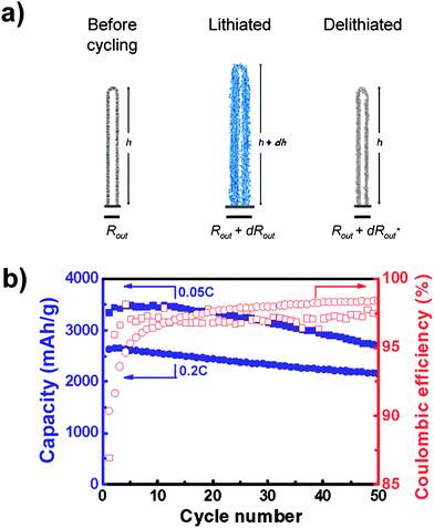 | ||
| Fig. 8 a) Schematic illustration of the anisotropic volume change in nanotubes during cycling. b) Specific capacity and Coulombic efficiency of silicon nanotubes cycled at rates of 0.05C (squares) and 0.2C (circles). Reproduced from Ref. 57 by permission of the American Chemical Society. | ||
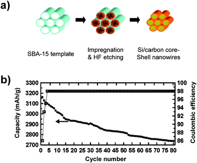 | ||
| Fig. 9 a) Schematic illustrating the synthesis of Si/carbon core/shell nanowires using mesoporous SBA-15 as the template. b) Specific capacity and Coulombic efficiency of carbon-coated silicon nanowires. Reproduced from Ref. 58 by permission of the American Chemical Society. | ||
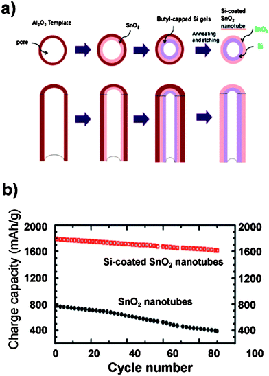 | ||
| Fig. 10 a) Schematic illustration of the synthesis of Si-coated SnO2 nanotubes using Al2O3 membranes as a template. b) Specific capacity of SnO2 nanotubes (filled circles) and silicon-coated SnO2 nanotubes (open squares). Reproduced from Ref. 61 by permission of the Royal Society of Chemistry. | ||
Si nanowires and related one-dimensional (1-D) nanostructures have demonstrated facile strain relaxation, suggesting this morphology may withstand the stresses during cycling and avoid pulverization. Deposition directly onto the current collector and the 1-D electrical conduction pathway further makes conductive additives unnecessary. However, significant challenges including low-throughput syntheses, high reactivity with the electrolyte, and low active material masses remain. Hence, it remains to be seen if nanowire-based batteries can be commercially viable for applications in large batteries using current technology.
3.3 Nanostructure morphologies—nanoparticles
Particle-based anodes combining electrochemically active silicon nanoparticles mixed with conductive additives and binders may have an advantage because the often simple particle syntheses can be easily scaled up. The capacity of particulate anodes containing conductive additives and either Si or Si-based composite nanoparticles is seen to increase as silicon content increases, however, higher silicon content and the concomitant expansion increase leads to lower reversible capacity. By decreasing the particle size, cycling stability can be enhanced compared to larger particles cycled under the same conditions, with less pulverization of particles observed in SEM micrographs of the cycled materials.88,89 Irreversible capacity losses in the first cycle are correlated with the nanoparticle diameter, with the irreversible capacity increasing as nanoparticle diameter decreases.114Nanoparticle size should therefore be optimized to achieve a balance between managing both material stress and SEI layer formation. A uniform distribution of silicon particles within the inactive matrix to provide isotropic volume expansion is also critical to minimizing the mechanical stress during lithiation.61![[thin space (1/6-em)]](https://www.rsc.org/images/entities/char_2009.gif) :
:![[thin space (1/6-em)]](https://www.rsc.org/images/entities/char_2009.gif) 1 weight ratio with carbon black showed a reversible capacity above 1700 mAhg−1 over ten cycles when the cycling voltage was limited to between 0.0–0.8 V to limit lithiation and volumetric expansion.89 Smaller silicon nanoparticles (with diameters ranging from 10–20 nm) showed reversible capacities over 2000 mAhg−1.114 In each of these reports, conductive additives were added to achieve good electrical conduction, and they may have buffered the volume expansion as well.
1 weight ratio with carbon black showed a reversible capacity above 1700 mAhg−1 over ten cycles when the cycling voltage was limited to between 0.0–0.8 V to limit lithiation and volumetric expansion.89 Smaller silicon nanoparticles (with diameters ranging from 10–20 nm) showed reversible capacities over 2000 mAhg−1.114 In each of these reports, conductive additives were added to achieve good electrical conduction, and they may have buffered the volume expansion as well.
The limited cycling lifetime of particulate-based anodes may be attributed to a combination of delamination of the particulate films with repeated expansion/contraction, irreversible reactions involving the electrolyte, and poor electrical conductivity resulting from a discontinuous current pathway. To address these possible causes, research has turned towards the use of composite nanoparticles.
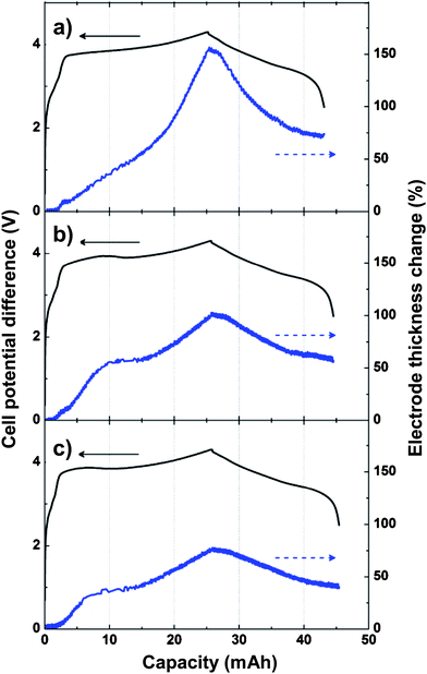 | ||
| Fig. 11 Change of electrode thickness during a single lithiation/delithiation cycle for a) Si/graphite composite electrode, b) Si/graphite composite electrode containing 5% polymer microspheres, and c) Si/graphite composite electrode containing 10% polymer microspheres. Reproduced from Ref. 77 by permission of Elsevier. | ||
A good matrix material should be an electronic and ionic conductor to facilitate charge transport between the silicon particles and current collector and assist lithium transport between the electrolyte and active material. Because exposure of silicon to the electrolyte results in progressive SEI formation during cycling, an elastic matrix that coats silicon conformally and resists fracture during cycling could improve SEI stability to reduce irreversible capacity and enhance cyclability.
The use of an silicon/inactive matrix was first demonstrated using a LixSi/Li2.6Sn composite.15 Preferential lithiation of the LixSi was achieved by restricting the upper and lower potentials within a voltage region in which Li2.6Sn is electrochemically inactive. Nickel/silicon, silver/silicon, and titanium carbide/silicon composites have since shown that stable cycling with small capacity decreases per cycle could be achieved, with reversible capacities 30–240% higher than graphite.79,86,87,93,94 However, the bulk of research into silicon composite anodes has focused on carbon matrixes because of carbon's abundance, well-understood chemistry, and the advantages that carbon can offer over other possible matrix materials.
The benefits of a carbon matrix are threefold: first, carbon is highly conductive, and provides efficient electron transport; second, carbon is lightweight and ductile, so it is able to accommodate volume expansion by the active material; and lastly, carbon is well known to form stable SEI layers in aprotic organic electrolytes, which may minimize capacity loss due to irreversible reactions. In addition, carbon coatings on silicon electrodes have been reported to modify the SEI morphology. For example, carbon-coated silicon electrodes exhibited smooth surfaces with limited pore structure, compared to the visibly cracked and porous morphology seen with pure silicon electrodes.78
Silicon/carbon composites are typically synthesized by mechanical milling of the active and matrix materials, or viapyrolysis of carbon and silicon precursors to yield silicon embedded in a carbonaceous matrix. The carbon matrix in nanocomposites often has limited insertion capacity relative to graphite, and does not contribute appreciably to the capacity of silicon nanocomposites. Nonetheless, this does not appear to be a detriment to composite electrodes, which have demonstrated better cycling and higher capacities when compared to silicon/graphite mixture anodes.64 The uniform carbon deposition during pyrolysis or prolonged ball milling in many composites results in intimate contact between carbon and silicon, enhancing conduction and surface passivation.
3.3.2.1 Nanocomposites synthesized viaball milling. The reversible capacities of ball milled nanocomposites typically range from 500–1000 mAhg−1.68–87,132–134 The high capacities of ball milled composites may arise from the small particle sizes (typically on the order of a few tens of nanometers), and may additionally benefit from efficient dispersal of highly conductive additives such as graphite, carbon blacks, and carbon nanotubes with the active material in ball milled composites. Furthermore, the abundant interparticle void spaces that can result from ball milling may help manage volume changes to provide improved cycling stability.
An anode based on silicon nanopowder ball milled with different types of carbon black and cellulose fibers demonstrated a reversible capacity of 2560 mAhg−1 in the second cycle and a reversible capacity of 1800 mAhg−1 after 50 cycles (Fig. 12).85 The capacity and reversibility were enhanced by the addition of the inactive carbons. The composite using XE2 carbon black achieved higher capacity than the composite using Super P carbon black, probably because the smaller XE2 particles could fill the void spaces more efficiently to provide better electrical contact with silicon. Nanocomposites synthesized by milling Si nanopowder with graphite and single-walled carbon nanotubes showed an initial discharge capacity above 1100 mAhg−1, with reversible capacities over 1000 mAhg−1 after 30 cycles.107 Even longer cycling lifetimes can be achieved by combining ball milling with pyrolysis of carbon-containing precursors to yield a protective carbon layer overcoating the nanosized electroactive silicon. This method has demonstrated reversible capacity as high as 650 mAhg−1 over 200 cycles and a small capacity loss (less than 0.05% per cycle) after the irreversible loss in the first cycle, behavior consistent with the formation of a stable SEI layer on carbon-based electrodes.72 Higher yet reversible capacities were reported for nanocomposites synthesized by ball milling of Si powder followed by pyrolysis of benzene.90 Reversible capacities of 1000 mAhg−1 were reported, although fewer cycles (55 cycles) were examined in this case.
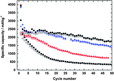 | ||
| Fig. 12 Specific capacities of electrodes using pure Si nanoparticles (n-Si) (squares), n-Si/cellulose (triangles), n-Si/cellulose/XE2 (circles); and n-Si/cellulose/Super P (stars), respectively. Open symbols correspond to discharge (delithiation) and closed symbols correspond to charge (lithiation). Reproduced from Ref. 85 by permission of Elsevier. | ||
3.3.2.2 Nanocomposites synthesized viapyrolysis. Silicon/carbon composites synthesized viapyrolysis of organic precursors mixed with nanoparticulate silicon78,80,81,83,84,95,97,102,103 or direct pyrolysis of single-source organosilicon precursors101,105 often display reversible capacities higher than graphite, but lower than those of ball milled silicon/carbon composites. The reversible capacities demonstrated typically range from about 300–700 mAhg−1 over a few dozen cycles,78,80,81,83,84,95,97,103,105,113,114,135 although a few notable exceptions using hierarchical composite structures will be discussed below. These relatively modest capacities may be due in part to the higher percentages of the inactive species that adds to the anode mass but does not contribute to the capacity. Other contributions to the lower capacities may include the larger size of silicon particles (100 nm or greater in diameter) which often agglomerate into even larger particles that are more vulnerable to fracture and pulverization during cycling, and formation of an oxide layer between the silicon and carbon coating during pyrolysis with oxygen-containing organic precursors.97 Nanocomposites synthesized using citric acid as the carbon source have shown moderately high reversible capacities, with the best nanocompsite showing a reversible capacity of 1120 mAhg−1 after 100 cycles.95 Similar reversible capacities over more limited cycling have also been reported for nanocomposites using various polymers as the carbon source.76
The pyrolysis or annealing temperature of carbon/silicon nanocomposites can have a marked influence on the capacity and cycling retention. Increasing the heat treatment temperature can reduce first cycle irreversible capacity loss by reducing the porosity of the carbon coating and decreasing the surface area available to react with the electrolyte.73 High temperature pyrolysis reduces the total carbon content.81Annealing at higher temperatures also results in thinner carbon layers, due to an increase of the degree of carbon layer ordering.95,136 The degree of layer ordering can be correlated with the capacity, due to the limited lithium insertion into ordered carbon than in disordered carbons.96
High reversible capacities have been reported for hierarchical porous nanocomposites synthesized using pyrolysis. A reversible capacity at 1C of 1530 mAhg−1 after 100 cycles with a per cycle capacity loss just over 0.5% was achieved using a hierarchical silicon/carbon composite synthesized by silicon and subsequent carbon deposition onto an annealed carbon black scaffold to obtain a carbon black/silicon/amorphous carbon structure (Fig. 13).100 Even after 100 cycles, the capacity was quite stable and the Coulombic efficiency was near 100%. This rather impressive performance may be the result of the interesting hierarchical and porous nature of the silicon/carbon composite. The annealed carbon black scaffold, which has only limited electroactivity (100mAhg1),100 is not expected to fracture due to expansion during lithiation, and the continuous electron current path provided by the scaffold may also reduce ohmic polarization. The second carbon coating process likely serves to protect the electroactive silicon from side reactions by facilitating the formation of a stable SEI layer.
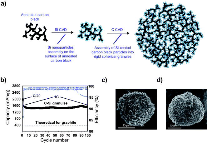 | ||
| Fig. 13 a) Schematic drawing of a hierarchical composite comprised of silicon particles deposited onto an annealed carbon black framework, and b) The specific capacity of the hierarchical silicon/carbon composite. Reproduced from Ref. 100 by permission of Nature Publishing Group. | ||
3.4 Nanostructure morphologies—mesoporous electrodes
Some notable examples of high capacity particulate composite electrodes are found with porous morphologies that address both the volumetric expansion and irreversible reactions following electrolyte exposure.9 Stable cycling with enhanced capacity has been reported for mesoporous carbon or metal oxides electrodes,137–140 suggesting this morphology could successfully manage volumetric changes in silicon anodes if SEI formation can be controlled. Macroporous crystalline silicon particles coated with < 10 nm of amorphous carbon demonstrated a reversible capacity of 2780 mAhg−1 after 100 cycles, with an irreversible capacity of 11% in the first cycle.110 The macroporous structure, which was preserved during cycling, enhances cycling lifetime and reversibility by acting as an expansion buffer to prevent electrode pulverization and subsequent loss of electrical conductivity. The irreversible capacity loss is lower in this composite than the best performing silicon nanowire anodes, suggesting that the porous structure can successfully manage the stresses associate with expansion. Additionally, coating the silicon microstructure with sufficiently thick carbon layers may lead to the formation of a stable SEI layer, reducing electrolyte decomposition at the surface.Nanocomposites that use mesoporous carbon frameworks to support silicon nanoparticles have exhibited high capacity and reversibility.100,111Carbon inverse-opals coated with amorphous silicon (carbon/silicon inverse-opal) synthesized via templating with ordered colloidal spheres and subsequent silicon deposition (Fig. 14) showed a capacity above 2100 mAhg−1 after 145 cycles, whereas the capacity of a silicon inverse-opal coated with amorphous carbon (silicon/carbon inverse-opal) was completely lost by the 11th cycle.111 The capacity retention and Coulombic efficiency increased with increasing pore size (Table 1), presumably due to the greater ability to buffer the volume expansion with increasing pore volume. The drastic difference in cycling stability resulted from the highly different mechanical stability of these nanostructures. Carbon provides a stable framework for the composite due to its low volume expansion during lithiation. SEM images revealed that the framework of the carbon/silicon inverse-opal, which undergoes less volume expansion, remained intact after electrochemical cycling. On the other hand, the cycled silicon/carbon inverse-opal collapsed completely, leading to the loss of capacity.
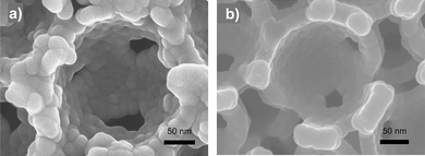 | ||
| Fig. 14 A carbon inverse-opal coated with amorphous silicon a) before cycling, and b) after 145 lithiation/delithiation cycles. Reproduced from Ref. 111 with permission from Wiley-VCH Verlag GmbH & Co. | ||
| Cycle | Sphere size (nm) | 250 | 480 | 890 | |||||
|---|---|---|---|---|---|---|---|---|---|
| Film thickness (μm) | 5 | 10 | 5 | 10 | 15 | 5 | 10 | 15 | |
| 1 | Capacity (mAh/g) | 2406 | 1890 | 1905 | 2557 | 1736 | 2165 | 2195 | 2374 |
| Coulombic efficiency (%) | 71.2 | 67.3 | 75.5 | 76.5 | 75.7 | 78.1 | 79.5 | 77.5 | |
| 145 | Capacity (mAh/g) | 88.6 | 56.2 | 82.7 | 86.9 | 72.4 | 87.6 | 84.1 | 91.0 |
| Coulombic efficiency (%) | 97.6 | 95.6 | 98.2 | 98.8 | 98.4 | 98.2 | 96.8 | 97.8 | |
3.5 Summary of nanoscale and nanostructured silicon anode performance
As we have discussed, high capacities and reversible cycling can be achieved using nanoscale and nanostructured silicon anodes. However, the performance for a given morphology varies from report to report. Data Tables ESI-1 to ESI-7 in the electronic supplementary information† summarize the morphology, composition, and method of preparation of those nanoscale and nanostructured silicon anodes reported in the recent literature, along with their electrochemical performance when the data have been clearly and reliably presented or can be estimated. When the appropriate electrochemical data was given in the report, we use the data directly. In all other cases, we have estimated the values from the information provided. For full details of the electrochemical performance, the reader is referred to the original report. In the tables, Qd1 corresponds to the first discharge (delithiation) capacity. The irreversible capacity in the first cycle (Qirr1) is calculated as the difference between the first charge (lithiation) and discharge capacities. The reversible capacity (Qr,N) is the discharge capacity in the Nth cycle.Each of the morphologies we have reviewed has unique advantages and challenges to be overcome. Using current synthetic techniques, the low throughput synthesis of thin films, nanowires and nanotubes, and other nanostructured morphologies could lead to high initial costs, at least until more scalable and inexpensive preparation techniques are developed. The hope is that the increased costs of these nanomaterials may be offset by their high capacities, though the very low cost of battery-grade graphite is actually quite hard to compete with. Nanoparticulate morphologies synthesized viaball milling or pyrolysis have lower cost, high-throughput syntheses, although more modest capacities have been demonstrated by active materials synthesized using these methods thus far. An additional challenge facing many nanoscale morphologies is the lower amount of active material in nanostructured electrodes when compared to bulk materials, which could result in lower actual total capacity for per unit area of the electrodes. When moving from bulk to nanostructured morphologies, we need to make sure that the increase in capacity gained by nanostructuring will indeed improve the total cell capacity. Additionally, more attention needs to be paid to the volumetric capacity, as opposed to just the gravimetric capacity, since the former is the limiting factor for high energy density batteries in practical applications.
4. Other factors influencing stability and performance
In addition to structure and morphology, several other factors influence the capacity and cycling lifetime of nanoscale and nanostructured silicon anodes, including solvent, additive, and binder compositions, as well as substrate effects, which determine the nature of the passivation layer and mechanical properties of the electrode. For nanoscale morphologies with large surface-to-volume ratios, surface passivation is perhaps the most challenging to control. Understanding how these factors influence the composition and morphology of the SEI layer is therefore essential.The difficulty in forming a stable passivation layer on nanostructured silicon electrodes in particular is caused by the expansion mismatch between silicon and the SEI layer. This mismatch can lead to cracking of the SEI layer and further reduction of the electrolyte on freshly exposed silicon surface and continuous capacity loss. Focus has therefore turned towards modifying the electrolytes, either by replacing carbonate-based electrolytes with new solvent compositions, or through the use of additives to facilitate healing when fracture does occur.
Less is known about the composition of the SEI layer that forms in other electrolytes, such as those based on room temperature ionic liquids (RTILs) and mixtures of RTILs with polymers that are being considered as alternatives to organic-based electrolytes due to their low flammability and larger solvent stability window. While there are no studies detailing the SEI composition on silicon electrodes in RTILs, it appears that a passivating layer does exist. The lower potential limit of RTILs and RTIL/polymer mixtures typically ranges from 0 to 1.5 V (vs.Li/Li+) and depends on the both the ionic liquid and any co-solvents present.5 The electrochemical potential of silicon therefore lies outside the window of thermodynamic stability for some RTIL solvent compositions. Studies of graphite electrodes cycled in RTILs show SEI formation can occur both in neat RTILs, and in RTILs combined with molecular additives such as EC or vinylene carbonate (VC).144,145
Stable cycling of amorphous silicon has been reported using 1-methyl-1-propylpiperidinium bis(trifluoromethylsufonyl)imide (MPPpTFSI) with the lithium bis(trifluoromethylfulfonyl)imide salt (LiTFSI).44 A detailed study of the passivation layer was not included, however, the large irreversible capacity in the first cycle (approximately 28%) suggests electrode passivation from electrolyte decomposition may have occurred.
Lithium bis(oxalato) borate (LiBOB), which undergoes reductive decomposition at the silicon surface at higher potentials than commonly-used EC and LiPF6, is proposed to improve cycling stability by encouraging the formation of a less porous SEI layer, thus minimizing the formation of electrochemically inactive silicon-containing reaction products on the electrode surface.43LiBOB may block surface reactions with in situ generated HF to prevent the formation of inactive SiF62− or SiPF5.43,146 However, the addition of LiBOB may increase concentration polarization due to lower ionic conductivity in LiBOB-based electrolytes compared to LiPF6.147
The relationship between electrolyte ionic conductivity, interfacial resistance, and cell impedance is complex. LiBOB has shown promise for reducing the cell impedance when combined with other lithium salts. For example, LiBF4-based electrolytes have demonstrated lower charge transfer resistance at graphite electrodes than LiPF6-based electrolytes, but cycling stability is poor due to the poor ability to form a stable SEI layer.148 The addition of LiBOB to LiBF4-PC based electrolytes has been shown to enable stable SEI formation on graphite electrodes and improve cycling stability.148 It is a point of dispute at this time whether the impedance of cells containing LiBOB are greater or less than those containing LiPF6; the conflicting trends reported may be due to different salt concentrations used in the individual studies.142,147
The cycling stability possible in cells using LiBOB has been demonstrated for a 200 nm thick amorphous silicon film that achieved a reversible capacity as high as 3000 mAhg−1 over 100 cycles.43 Such high reversible capacity in silicon films with thicknesses greater than 100 nm have only been demonstrated over several dozens of charge/discharge cycles in electrolytes without LiBOB.31,32,41X-ray photoelectron spectroscopy (XPS) and Fourier transform infrared spectroscopy (FTIR) analysis have shown that the SEI layer on electrodes cycled in electrolytes containing LiBOB are similar to those formed in LiPF6-based electrolytes, although lower signal intensity corresponding to Li2CO3, LiOH, and Li2O was found using LiBOB electrolyte. Electrodes cycled with LiBOB electrolytes additionally have lithium oxalate (Li2C2O4) incorporated into the SEI layer, which may be better at protecting against further electrolyte reaction after the initial SEI formation.
VC is reduced at higher potential than EC, thus it can greatly influence SEI composition directly on the electrode surface.142 When studied as an additive for graphite-based electrodes, VC was found to yield reduction products that exhibit lower lithium ion conductivity than EC reduction products, increasing the cell impedance.142 Increased interfacial resistance has been reported previously to result from electrochemical polymerization during cycling.116,147 Despite this apparent drawback, the addition of VC has improved both the Coulombic efficiency and cycling retention of silicon electrodes in at least one study, with the electrode maintaining 50% of the initial capacity after 500 cycles.116 In the absence of VC, the capacity dropped markedly before the 100th cycle, and the electrode failed before the 200th cycle. SEM imaging revealed that the electrode cycled with VC had a smooth surface with small cracks believed to form during delithiation, compared to a much rougher surface with protruding crystallites and an inhomogeneous appearance without VC. In addition, the impedance of the SEI layers were reported to remain constant for the electrode cycled with VC but increased with each cycle without VC.
The addition of fluoroethylene carbonate (FEC) to alkyl carbonate solvents with LiPF6 has also been shown to enhance capacity retention and increase Coulombic efficiency.42 The discharge capacity retention of 200 nm thick silicon after 80 cycles was 88.5% and 67.9% for electrodes cycled with and without FEC respectively. A smoother passivation layer was observed on the surface of the electrode cycled in FEC, suggesting that the additive may encourage formation of a more stable or faster healing SEI layer. Investigation of the differential capacity suggests that FEC is reduced at higher potentials than EC, altering the SEI composition to include fluorinated silicon species and forming a more stable passivation layer. It has been suggested that fluorine can shorten the length of oligomer chains present in the SEI layer, leading to compact passivation films.142
Silane-based additives such as monomethoxy trimethyl silane (CH3OSi(CH3)3), dimethoxy dimethyl silane ((CH3O)2Si(CH3)2), and trimethoxy methyl silane ((CH3O)3SiCH3), have been demonstrated to decrease the extent of SEI formation and improve cycle life of thin silicon films by reducing the consumption of active material.48,50,52 The SEI mass was determined by using an electrochemical quartz crystal microbalance to measure the mass change prior to the onset of lithiation. The alkoxy silane functionalites are believed to protect the anode surface by reacting with the silicon surface hydroxyls to form stable ![[triple bond, length as m-dash]](https://www.rsc.org/images/entities/char_e002.gif) Si–O–Si
Si–O–Si![[triple bond, length as m-dash]](https://www.rsc.org/images/entities/char_e002.gif) bonds, making the surfaces less conducive to electrolyte reduction and SEI layer formation.48FTIR investigation revealed that silane addition encouraged formation of stable alkyl carbonate salts (R–OCO2−Mn+, R = alkyl and M = Li or Si), carboxylic acid metal salt functionalities (R–CO2−Mn+, M = Li or Si), and PF-containing species, in contrast to the primarily PF-containing species layer formed in the absence of silane.50 The enhanced cycling lifetime suggests that alkyl carbonates and carboxylic acid metal salt functionalities effectively passivate the silicon surface. Smooth films were seen on electrode surfaces after cycling when silane additive was present, whereas the surface morphology after cycling without silane was visibly rougher.
bonds, making the surfaces less conducive to electrolyte reduction and SEI layer formation.48FTIR investigation revealed that silane addition encouraged formation of stable alkyl carbonate salts (R–OCO2−Mn+, R = alkyl and M = Li or Si), carboxylic acid metal salt functionalities (R–CO2−Mn+, M = Li or Si), and PF-containing species, in contrast to the primarily PF-containing species layer formed in the absence of silane.50 The enhanced cycling lifetime suggests that alkyl carbonates and carboxylic acid metal salt functionalities effectively passivate the silicon surface. Smooth films were seen on electrode surfaces after cycling when silane additive was present, whereas the surface morphology after cycling without silane was visibly rougher.
4.2 Substrate influence
Delamination of the active layer from the current collector contributes to anode capacity degradation. Modification of the metal surface and the addition of buffer layers to provide greater adhesion could therefore improve capacity retention and cycling lifetimes of thin film silicon anodes. Electrochemical roughening of nickel or copper substrate surfaces has been used to improve adhesion of silicon films to the substrate.38,41,46,49,51 Surface modification could create anchor points for the deposited active material to adhere to, thus allowing electrical contact with the substrate to be maintained even if the active film itself shows cracking. This technique has been successful for attaining reversible capacities near 1000 mAhg−1 over 20 cycles for a thick 6 μm silicon film.49 Despite this improvement, the capacity is still lower than nanoparticle composite electrodes, which have shown twice this capacity for 100 or more cycles.110,111 Improved film adhesion has also been reported for silicon thin films sputtered onto copper foils that had been pretreated using lanthanum Plasma Immersion Ion Implantation (PIII).149 Deposition of thin Ni layers on roughened copper substrates was reported to improve initial capacity and reduce the irreversible capacity loss in silicon thin film electrodes, although rapid deterioration of the capacity after the first cycle still occurred due to delamination of the buffer layer from the copper substrate.46 Heat treatments could improve binder adhesion to both the substrate and active material and have additionally been shown to increase cycling lifetimes.41,150Annealing silicon films sputtered onto roughened copper substrates has been reported to increase capacity retention from 61.3% to 78.5% for 500 cycles by promoting interdiffusion of silicon and copper at the interface to improve the film adhesion strength.514.3 Binder influence
The type of binder used in particulate electrodes can greatly influence the cycling lifetime. Poly(vinylidene) difluoride (PVdF) has been the most frequently used binder in bulk powder electrodes, but this thermoplastic binder cannot sustain the elongation that occurs during volumetric expansion, leading to rapid capacity fade. Electrode polarization has been found to increase during cycling when using PVdF, suggesting degrading electrical contact after repeated electrode expansion/contraction.90 The ability of PVdF to maintain cycling stability can be enhanced by heat treatment prior to electrochemical cycling, although severe capacity fade is still seen within a few tens of cycles.150Poly(acrylic) acid (PAA) has been shown to improve cycle life by enhancing the adhesion of graphite electrodes to copper current collectors.151PAA also improved cycling stability of a silicon/carbon composite, both when used alone and when mixed with sodium carboxymethylcellulose (SCMC).152 This enhancement may result from the formation of chemical linkages between the composite and these acidic binders. Both carbon and silicon surfaces contain hydroxyl functionalities that can react with carboxylic acid functionalized binders in an esterification reaction to ‘tether’ the active material to the binder.153
Sodium carboxymethylcellulose (SCMC) is a water soluble elastomeric binder that can be blended with styrene butadiene rubber (SBR) to achieve high elongation without tearing. The elastomeric nature combined with the ability of SCMC to tether to the active material are proposed to extend cycling lifetimes in silicon powder electrodes.91,154Electrodes using nanoscale (∼ 100 nm) silicon powder processed in buffered solution (pH = 3.0) with SBR-SCMC demonstrated a reversible capacity of 960 mAhg−1 over 700 cycles, a cycling lifetime unprecedented in powder-based silicon anodes without SBR-SCMC.91Ester linkages confirmed using FTIR measurements suggest that tethering was responsible for the marked improvement in the cyclability of the alloy electrodes. Silicon and carbon-coated silicon electrodes using SBR/SCMC in a 1![[thin space (1/6-em)]](https://www.rsc.org/images/entities/char_2009.gif) :
:![[thin space (1/6-em)]](https://www.rsc.org/images/entities/char_2009.gif) 1 weight ratio demonstrated enhanced cycling stability compared to electrodes using PVdF, with stable capacities of approximately 600 and 1000 mAhg−1 respectively over 55 cycles.90 A control electrode using PVdF failed after 5 cycles, with the capacity quickly dropping to zero.
1 weight ratio demonstrated enhanced cycling stability compared to electrodes using PVdF, with stable capacities of approximately 600 and 1000 mAhg−1 respectively over 55 cycles.90 A control electrode using PVdF failed after 5 cycles, with the capacity quickly dropping to zero.
4.4 Conductive additives
The choice of the conductive additive can have a significant impact on electrochemical performance. To reduce polarization, a continuous electron-conducting pathway must be formed. The addition of carbon nanotubes, which have smaller diameters compared to the active material, was shown to enhance both capacity and cycling stability by forming a more efficient percolation pathway compared to when larger carbon black particles were used (Fig. 15).63 However, CNT-containing composites can suffer high irreversible capacity loss to SEI formation, due to the high surface area available to react with the electrolyte.107 The reversible capacity has also been shown to increase as the carbon black particle size decreases, suggesting better interparticle contact can be achieved using smaller carbon black particles.85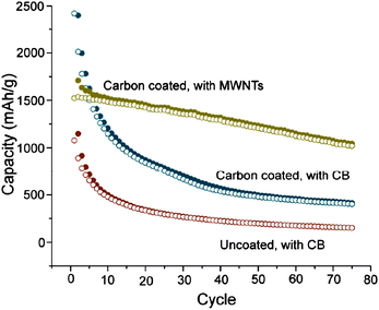 | ||
| Fig. 15 Specific capacity of uncoated and carbon-coated Si nanowires using either carbon black (red and blue circles) or multi-walled carbon nanotubes (gold circles) as the conductive additive. Reproduced from Ref. 63 by permission of the Americal Chemical Society. | ||
5. Summary and perspective
The discussion in this review has illustrated that silicon anodes have advantages over conventional graphite anodes in lithium batteries, but significant challenges need to be overcome before silicon anodes can be utilized in practical lithium batteries. Morphology can have a major impact on the performance and cyclability of the silicon anode. Bulk electrodes fail within a few charge/discharge cycles due to the extremely large volumetric change that occurs during lithiation and delithiation. Nanoscale morphologies have the potential to achieve long cycling lifetimes and good reversibility if challenges such as stress management and formation of a stable passivation layer during cycling can be overcome. Over the last decade, tremendous progress has been made in addressing these challenges by using nanoscale or nanostructured silicon anodes, such as thin films, 1-D nanowires or nanotubes, nanoparticles, mesoporous nanostructures, and their respective nanocomposites. Despite the variations of reported performance, a consistent trend has been emerging that storage capacities as high as 2000–2500 mAhg−1 for thin film silicon anodes and 1000–2000 mAhg−1 in other silicon nanostructure morphologies with rather impressive cycling lifetimes up to a couple hundred cycles at practical charge/discharge rate can be reproducibly achieved. Long cycling lifetimes have most frequently been observed when four critical factors were properly addressed: i) use of nanoscale-dimension silicon to allow the relaxation of the strain and stress during the volume expansion/contraction associated with lithiation/delithiation; ii) incorporation of void/free space or softer inactive material matrices or additives to accommodate the volume expansion; iii) efficient electronic and ionic conduction from silicon to the current collectors that can be maintained during cycling; and iv) furthermore, the formation of a stable and non-porous passivating SEI layer that can tolerate the silicon expansion and avoid cracking, or can be healed readily so that continual capacity loss can be minimized.These lessons suggest that future research should explore more structurally and compositionally complex hierarchical composite nanostructures with internal void/pore space, in addition to the simple one-component silicon nanostructures already extensively investigated. Considering the potential large-scale energy applications of rechargeable lithium batteries, such as in hybrid and plug-in electric vehicles or electrical power storage, the scalability, manufacturability, and cost of the nanomaterials will also be important to the eventual success in their practical applications. Although the volumetric capacity has not often been reported for nanostructured silicon anodes so far, more attention should be paid to this important parameter in future research. Particulate hierarchical composite nanostructures that can both manage strain/stress and the surface passivation may be the most promising direction for large-scale applications. For example, composite mesoporous particulate anodes could be attractive: the strain/stress can be addressed by the nanoscale dimension and the volume expansion accommodated by the void space, although the ability to form a stable SEI layer without high irreversible capacity in the first cycle has not been well studied with mesoporous electrodes and may be difficult to achieve due to the extremely high surface-to-volume ratio. Composites in which silicon is conformally coated with an amorphous carbon layer could facilitate the formation of a stable SEI layer. The expansion mismatch between silicon and the SEI layer during cycling and resultant cracking of the SEI layer causes capacity degradation, therefore methods to limit SEI layer cracking, such as designing the proper nanostructure geometry and controlling the degree of lithiation to minimize the expansion, and using additives to encourage quick healing of the layer during cycling need to be further investigated. It is quite promising that continual development of these and other strategies and diverse varieties of silicon anode nanomaterials will lead to the practical applications of silicon anodes in practical lithium batteries at a large scale.
Acknowledgements
We thank the University of Wisconsin-Madison graduate school, the Sloan Research Fellowship, the Research Corporation through a Cottrell Scholar Award, the ACS ExxonMobil Solid State Chemistry Fellowship, and the DuPont Young Professor Grant for support. We thank Prof. Y.-M. Chiang for helpful discussions. S. J. also thanks the support of his research by NIH, DOE, and NSF.References
-
D. Linden, Handbook of Batteries, 2nd edn, McGraw-Hill, New York, 1985 Search PubMed
.
- J. R. Owen, Chem. Soc. Rev., 1997, 26, 259–268 RSC
.
- D. Larcher, S. Beattie, M. Morcrette, K. Edstroem, J.-C. Jumas and J.-M. Tarascon, J. Mater. Chem., 2007, 17, 3759–3772 RSC
.
- Y. Wang and G. Cao, Adv. Mater., 2008, 20, 2251–2269 CrossRef CAS
.
- J. B. Goodenough and Y. Kim, Chem. Mater., 2010, 22, 587–603 CrossRef CAS
.
- U. Kasavajjula, C. Wang and A. J. Appleby, J. Power Sources, 2007, 163, 1003–1039 CrossRef CAS
.
- A. S. Arico, P. Bruce, B. Scrosati, J.-M. Tarascon and W. van Schalkwijk, Nat. Mater., 2005, 4, 366–377 CrossRef CAS
.
- H. Li, Z. Wang, L. Chen and X. Huang, Adv. Mater., 2009, 21, 4593–4607 CrossRef CAS
.
- J. Cho, J. Mater. Chem., 2010, 20, 4009–4014 RSC
.
- N. Kambe, M. S. Dresselhaus, G. Dresselhaus, S. Basu, A. R. McGhie and J. E. Fischer, Mater. Sci. Eng., 1979, 40, 1–4 CrossRef CAS
.
- D. Billaud, E. McRae and A. Herold, Mater. Res. Bull., 1979, 14, 857–864 CrossRef CAS
.
- H. Jung, M. Park, Y.-G. Yoon, G.-B. Kim and S.-K. Joo, J. Power Sources, 2003, 115, 346–351 CrossRef CAS
.
- S. Ohara, J. Suzuki, K. Sekine and T. Takamura, J. Power Sources, 2004, 136, 303–306 CrossRef CAS
.
- J. O. Besenhard, J. Yang and M. Winter, J. Power Sources, 1997, 68, 87–90 CrossRef CAS
.
- B. A. Boukamp, G. C. Lesh and R. A. Huggins, J. Electrochem. Soc., 1981, 128, 725–729 CAS
.
- WO Pat., 2009–IB53920 2010032159, 2010
.
- WO Pat., 2008–KR6420 2010035919, 2010
.
- US Pat., 2009–558454 2010062338, 2010
.
- US Pat., 2009–397629 2010051856, 2010
.
- US Pat., 2008–212580 2009075173, 2009
.
- WO Pat., 2009–US52511 2010014966, 2010
.
- US Pat., 2009–319812 2010176337, 2010
.
- WO Pat., 2008–KR3670 2009005247, 2009
.
- US Pat., 2008–181586 2009117468, 2009
.
- WO Pat., 2008–US70818 2009015175, 2009
.
- US Pat., 2008–130145 2009169994, 2009
.
- US Pat., 2007–808435 2008003503, 2008
.
- US Pat., 2006–387205 2007020521, 2007
.
- US Pat., 2005–106225 2006057463, 2006
.
- L. Y. Beaulieu, K. W. Eberman, R. L. Turner, L. J. Krause and J. R. Dahn, Electrochem. Solid-State Lett., 2001, 4, A137–A140 CrossRef CAS
.
- J. P. Maranchi, A. F. Hepp and P. N. Kumta, Electrochem. Solid-State Lett., 2003, 6, A198–A201 CrossRef CAS
.
- J. P. Maranchi, A. F. Hepp, A. G. Evans, N. T. Nuhfer and P. N. Kumta, J. Electrochem. Soc., 2006, 153, A1246–A1253 CrossRef CAS
.
- A. A. Arie, J. O. Song and J. K. Lee, Mater. Chem. Phys., 2009, 113, 249–254 CrossRef CAS
.
- M. D. Fleischauer, J. M. Topple and J. R. Dahn, Electrochem. Solid-State Lett., 2005, 8, A137–A140 CrossRef CAS
.
- C.-M. Hwang, C.-H. Lim, J.-H. Yang and J.-W. Park, J. Power Sources, 2009, 194, 1061–1067 CrossRef CAS
.
- L. Y. Beaulieu, T. D. Hatchard, A. Bonakdarpour, M. D. Fleischauer and J. R. Dahn, J. Electrochem. Soc., 2003, 150, A1457–A1464 CrossRef CAS
.
- J. Graetz, C. C. Ahn, R. Yazami and B. Fultz, Electrochem. Solid-State Lett., 2003, 6, A194–A197 CrossRef CAS
.
- M. Uehara, J. Suzuki, K. Tamura, K. Sekine and T. Takamura, J. Power Sources, 2005, 146, 441–444 CrossRef CAS
.
- J.-B. Kim, B.-S. Jun and S.-M. Lee, Electrochim. Acta, 2005, 50, 3390–3394 CrossRef CAS
.
- M. S. Park, G. X. Wang, H. K. Liu and S. X. Dou, Electrochim. Acta, 2006, 51, 5246–5249 CrossRef CAS
.
- T. Moon, C. Kim and B. Park, J. Power Sources, 2006, 155, 391–394 CAS
.
- N.-S. Choi, K. H. Yew, K. Y. Lee, M. Sung, H. Kim and S.-S. Kim, J. Power Sources, 2006, 161, 1254–1259 CrossRef CAS
.
- N.-S. Choi, K. H. Yew, H. Kim, S.-S. Kim and W.-U. Choi, J. Power Sources, 2007, 172, 404–409 CrossRef CAS
.
- V. Baranchugov, E. Markevich, E. Pollak, G. Salitra and D. Aurbach, Electrochem. Commun., 2007, 9, 796–800 CrossRef CAS
.
- E. Pollak, G. Salitra, V. Baranchugov and D. Aurbach, J. Phys. Chem. C, 2007, 111, 11437–11444 CrossRef CAS
.
- B. K. Lee, G. B. Cho, K. K. Cho and K. W. Kim, Diffus. Defect Data, Pt. B, 2007, 124–126, 1011–1014 Search PubMed
.
- J. O. Song, H. T. Shim, D.j. Byun and J. K. Lee, Diffus. Defect Data, Pt. B, 2007, 124–126, 1063–1066 Search PubMed
.
- Y.-G. Ryu, S. Lee, S. Mah, D. J. Lee, K. Kwon, S. Hwang and S. Doo, J. Electrochem. Soc., 2008, 155, A583–A589 CrossRef CAS
.
- T. Zhang, H. P. Zhang, L. C. Yang, B. Wang, Y. P. Wu and T. Takamura, Electrochim. Acta, 2008, 53, 5660–5664 CrossRef CAS
.
- S.-W. Song and S.-W. Baek, Electrochem. Solid-State Lett., 2009, 12, A23–A27 CrossRef CAS
.
- L. B. Chen, J. Y. Xie, H. C. Yu and T. H. Wang, J. Appl. Electrochem., 2009, 39, 1157–1162 CrossRef CAS
.
- C. C. Nguyen and S.-W. Song, Electrochim. Acta, 2010, 55, 3026–3033 CrossRef CAS
.
- H.-J. Ahn, Y.-S. Kim, W. B. Kim, Y.-E. Sung and T.-Y. Seong, J. Power Sources, 2006, 163, 211–214 CrossRef CAS
.
- M. Green, E. Fielder, B. Scrosati, M. Wachtler and J. S. Moreno, Electrochem. Solid-State Lett., 2003, 6, A75–A79 CrossRef CAS
.
- C. K. Chan, H. Peng, G. Liu, K. McIlwrath, X. F. Zhang, R. A. Huggins and Y. Cui, Nat. Nanotechnol., 2007, 3, 31–35
.
- L.-F. Cui, R. Ruffo, C. K. Chan, H. Peng and Y. Cui, Nano Lett., 2009, 9, 491–495 CrossRef CAS
.
- T. Song, J. Xia, J.-H. Lee, D. H. Lee, M.-S. Kwon, J.-M. Choi, J. Wu, S. K. Doo, H. Chang, W. I. Park, D. S. Zang, H. Kim, Y. Huang, K.-C. Hwang, J. A. Rogers and U. Paik, Nano Lett., 2010, 10, 1710–1716 CrossRef CAS
.
- H. Kim and J. Cho, Nano Lett., 2008, 8, 3688–3691 CrossRef CAS
.
- R. Huang, X. Fan, W. Shen and J. Zhu, Appl. Phys. Lett., 2009, 95, 133119–133113 CrossRef
.
- L.-F. Cui, Y. Yang, C.-M. Hsu and Y. Cui, Nano Lett., 2009, 9, 3370–3374 CrossRef CAS
.
- W. J. Lee, M.-H. Park, Y. Wang, J. Y. Lee and J. Cho, Chem. Commun., 2010, 46, 622–624 RSC
.
- M.-H. Park, M. G. Kim, J. Joo, K. Kim, J. Kim, S. Ahn, Y. Cui and J. Cho, Nano Lett., 2009, 9, 3844–3847 CrossRef CAS
.
- C. K. Chan, R. N. Patel, M. J. O'Connell, B. A. Korgel and Y. Cui, ACS Nano, 2010, 4, 1443–1450 CrossRef CAS
.
- W. Xu and J. C. Flake, J. Electrochem. Soc., 2010, 157, A41–A45 CrossRef CAS
.
- J. W. Choi, J. McDonough, S. Jeong, J. S. Yoo, C. K. Chan and Y. Cui, Nano Lett., 2010, 10, 1409–1413 CrossRef CAS
.
- K. Kang, H.-S. Lee, D.-W. Han, G.-S. Kim, D. Lee, G. Lee, Y.-M. Kang and M.-H. Jo, Appl. Phys. Lett., 2010, 96, 053110–053113 CrossRef
.
- W. Wang and P. N. Kumta, ACS Nano, 2010, 4, 2233–2241 CrossRef CAS
.
- C. S. Wang, G. T. Wu, X. B. Zhang, Z. F. Qi and W. Z. Li, J. Electrochem. Soc., 1998, 145, 2751–2758 CAS
.
- Z. P. Guo, E. Milin, J. Z. Wang, J. Chen and H. K. Liu, J. Electrochem. Soc., 2005, 152, A2211–A2216 CrossRef
.
- Z. P. Guo, J. Z. Wang, H. K. Liu and S. X. Dou, J. Power Sources, 2005, 146, 448–451 CrossRef CAS
.
- S.-H. Ng, J. Wang, D. Wexler, K. Konstantinov, Z.-P. Guo and H.-K. Liu, Angew. Chem., Int. Ed., 2006, 45, 6896–6899 CrossRef CAS
.
- T. Morita and N. Takami, J. Electrochem. Soc., 2006, 153, A425–A430 CrossRef CAS
.
- M. K. Datta and P. N. Kumta, J. Power Sources, 2007, 165, 368–378 CrossRef CAS
.
- J. Saint, M. Morcrette, D. Larcher, L. Laffont, S. Beattie, J.-P. Peres, D. Talaga, M. Couzi and J.-M. Tarascon, Adv. Funct. Mater., 2007, 17, 1765–1774 CrossRef CAS
.
- S. Cahen, R. Janot, L. Laffont-Dantras and J. M. Tarascon, J. Electrochem. Soc., 2008, 155, A512–A519 CrossRef CAS
.
- Y. Liu, Z. Y. Wen, X. Y. Wang, A. Hirano, N. Imanishi and Y. Takeda, J. Power Sources, 2009, 189, 733–737 CrossRef CAS
.
- S. S. Hwang, C. G. Cho and H. Kim, Electrochim. Acta, 2010, 55, 3236–3239 CrossRef CAS
.
- Y.-C. Yen, S.-C. Chao, H.-C. Wu and N.-L. Wu, J. Electrochem. Soc., 2009, 156, A95–A102 CrossRef CAS
.
- H. Kim, D. Im and S. G. Doo, J. Power Sources, 2007, 174, 588–591 CrossRef CAS
.
- Y. Eker, K. Kierzek, E. Raymundo-Pinero, J. Machnikowski and F. Beguin, Electrochim. Acta, 2010, 55, 729–736 CrossRef CAS
.
- P. Gu, R. Cai, Y. Zhou and Z. Shao, Electrochim. Acta, 2010, 55, 3876–3883 CrossRef CAS
.
- L. Su, Z. Zhou and M. Ren, Chem. Commun., 2010, 46, 2590–2592 RSC
.
- H. S. Kim, K. Y. Chung and B. W. Cho, Bull. Korean Chem. Soc., 2008, 29, 1965–1968 CrossRef CAS
.
- K. Wang, X. He, L. Wang, J. Ren, C. Jiang and C. Wan, Solid State Ionics, 2007, 178, 115–118 CrossRef CAS
.
- J. L. Gomez Camer, J. Morales, L. Sanchez, P. Ruch, S. H. Ng, R. Koetz and P. Novak, Electrochim. Acta, 2009, 54, 6713–6717 CrossRef CAS
.
- X. Yang, Z. Wen, X. Xu, Z. Gu and S. Huang, Electrochem. Solid-State Lett., 2007, 10, A52–A55 CrossRef CAS
.
- J. H. Song, W. K. Han, Y. K. Sun and S. G. Kang, Diffus. Defect Data, Pt. B, 2007, 124–126, 1035–1038 Search PubMed
.
- J. Yang, M. Winter and J. O. Besenhard, Solid State Ionics, 1996, 90, 281–287 CrossRef CAS
.
- H. Li, X. Huang, L. Chen, Z. Wu and Y. Liang, Electrochem. Solid-State Lett., 1999, 2, 547–549 CrossRef CAS
.
- W.-R. Liu, M.-H. Yang, H.-C. Wu, S. M. Chiao and N.-L. Wu, Electrochem. Solid-State Lett., 2005, 8, A100–A103 CrossRef CAS
.
- D. Mazouzi, B. Lestriez, L. Roue and D. Guyomard, Electrochem. Solid-State Lett., 2009, 12, A215–A218 CrossRef CAS
.
- M. Holzapfel, H. Buqa, W. Scheifele, P. Novak and F.-M. Petrat, Chem. Commun., 2005, 1566–1588 RSC
.
- W.-R. Liu, N.-L. Wu, D.-T. Shieh, H.-C. Wu, M.-H. Yang, C. Korepp, J. O. Besenhard and M. Winter, J. Electrochem. Soc., 2007, 154, A97–A102 CrossRef CAS
.
- Z. Y. Zeng, J. P. Tu, X. H. Huang, X. L. Wang and J. Y. Xiang, Thin Solid Films, 2009, 517, 4767–4771 CrossRef CAS
.
- S. H. Ng, J. Wang, D. Wexler, S. Y. Chew and H. K. Liu, J. Phys. Chem. C, 2007, 111, 11131–11138 CrossRef CAS
.
- Y. Kwon and J. Cho, Chem. Commun., 2008, 1109–1111 RSC
.
- Y. S. Jung, K. T. Lee and S. M. Oh, Electrochim. Acta, 2007, 52, 7061–7067 CrossRef CAS
.
- P. Zuo, G. Yin and Y. Ma, Electrochim. Acta, 2007, 52, 4878–4883 CrossRef CAS
.
- S. Y. Chew, Z. P. Guo, J. Z. Wang, J. Chen, P. Munroe, S. H. Ng, L. Zhao and H. K. Liu, Electrochem. Commun., 2007, 9, 941–946 CrossRef CAS
.
- A. Magasinski, P. Dixon, B. Hertzberg, A. Kvit, J. Ayala and G. Yushin, Nat. Mater., 2010, 9, 353–358 CrossRef CAS
.
- A. M. Wilson and J. R. Dahn, J. Electrochem. Soc., 1995, 142, 326–332 CAS
.
- J. Yang, B. F. Wang, K. Wang, Y. Liu, J. Y. Xie and Z. S. Wen, Electrochem. Solid-State Lett., 2003, 6, A154–A156 CrossRef CAS
.
- L. Chen, X. Xie, B. Wang, K. Wang and J. Xie, Mater. Sci. Eng., B, 2006, 131, 186–190 CrossRef CAS
.
- H. Guo, H. Zhao, C. Yin and W. Qiu, J. Alloys Compd., 2006, 426, 277–280 CrossRef CAS
.
- T. Kim, Y. H. Mo, K. S. Nahm and S. M. Oh, J. Power Sources, 2006, 162, 1275–1281 CrossRef CAS
.
- H. Ma, F. Cheng, J. Chen, J. Zhao, C. Li, Z. Tao and J. Liang, Adv. Mater., 2007, 19, 4067–4070 CrossRef CAS
.
- W. Wang and P. N. Kumta, J. Power Sources, 2007, 172, 650–658 CrossRef CAS
.
- A. Timmons and J. R. Dahn, J. Electrochem. Soc., 2007, 154, A444–A448 CrossRef CAS
.
- A. Timmons, A. D. W. Todd, S. D. Mead, G. H. Carey, R. J. Sanderson, R. E. Mar and J. R. Dahn, J. Electrochem. Soc., 2007, 154, A865–A874 CrossRef CAS
.
- H. Kim, B. Han, J. Choo and J. Cho, Angew. Chem., Int. Ed., 2008, 47, 10151–10154 CrossRef CAS
.
- A. Esmanski and G. A. Ozin, Adv. Funct. Mater., 2009, 19, 1999–2010 CrossRef CAS
.
- C. Martin, M. Alias, F. Christien, O. Crosnier, D. Belanger and T. Brousse, Adv. Mater., 2009, 21, 4735–4741 CAS
.
- Y. H. Xu, G. P. Yin, Y. L. Ma, P. J. Zuo and X. Q. Cheng, J. Mater. Chem., 2010, 20, 3216–3220 RSC
.
- H. Kim, M. Seo, M.-H. Park and J. Cho, Angew. Chem., Int. Ed., 2010, 49, 2146–2149 CrossRef CAS
(S2146/2141–S2146/2144).
- D. Aurbach, Y. Ein-Eli, O. Chusid, Y. Carmeli, M. Babai and H. Yamin, J. Electrochem. Soc., 1994, 141, 603–611 CAS
.
- L. Chen, K. Wang, X. Xie and J. Xie, J. Power Sources, 2007, 174, 538–543 CrossRef CAS
.
- Y. M. Lee, J. Y. Lee, H.-T. Shim, J. K. Lee and J.-K. Park, J. Electrochem. Soc., 2007, 154, A515–A519 CrossRef CAS
.
- C. K. Chan, R. Ruffo, S. S. Hong and Y. Cui, J. Power Sources, 2009, 189, 1132–1140 CrossRef CAS
.
-
Binary Alloy Phase Diagrams, 2nd edn, ASM International, Materials Park, Ohio, 1990 Search PubMed
.
- N. Ding, J. Xu, Y. X. Yao, G. Wegner, X. Fang, C. H. Chen and I. Lieberwirth, Solid State Ionics, 2009, 180, 222–225 CrossRef CAS
.
- P. Limthongkul, Y.-I. Jang, N. J. Dudney and Y.-M. Chiang, J. Power Sources, 2003, 119–121, 604–609 CrossRef CAS
.
- M. N. Obrovac and L. Christensen, Electrochem. Solid-State Lett., 2004, 7, A93–A96 CrossRef CAS
.
- T. D. Hatchard and J. R. Dahn, J. Electrochem. Soc., 2004, 151, A838–A842 CrossRef CAS
.
- M. N. Obrovac and L. J. Krause, J. Electrochem. Soc., 2007, 154, A103–A108 CrossRef CAS
.
- G. W. Zhou, H. Li, H. P. Sun, D. P. Yu, Y. Q. Wang, X. J. Huang, L. Q. Chen and Z. Zhang, Appl. Phys. Lett., 1999, 75, 2447–2449 CrossRef CAS
.
- K. E. Aifantis and S. A. Hackney, Nanostruct. Mater. Electrochem., 2008, 319–347 Search PubMed
.
- R. A. Huggins and W. D. Nix, Ionics, 2000, 6, 57–63 CrossRef CAS
.
- E. M. Pell, Phys. Rev., 1960, 119, 1222–1225 CrossRef CAS
.
- B. M. Way and J. R. Dahn, J. Electrochem. Soc., 1994, 141, 907–912 CAS
.
- Y. Wu, S. Fang and Y. Jiang, J. Mater. Chem., 1998, 8, 2223–2227 RSC
.
- G. Yin, Y. Gao, P. Shi, X. Cheng and A. Aramata, Mater. Chem. Phys., 2003, 80, 94–101 CrossRef CAS
.
- Z. Chen, Y. Cao, J. Qian, X. Ai and H. Yang, J. Phys. Chem. C, 2010, 114, 15196–15201 CAS
.
- M.-S. Park, S. Rajendran, Y.-M. Kang, K.-S. Han, Y.-S. Han and J.-Y. Lee, J. Power Sources, 2006, 158, 650–653 CrossRef CAS
.
- G. X. Wang, L. Sun, D. H. Bradhurst, S. Zhong, S. X. Dou and H. K. Liu, J. Alloys Compd., 2000, 306, 249–252 CrossRef CAS
.
- A. M. Wilson, J. N. Reimers, E. W. Fuller and J. R. Dahn, Solid State Ionics, 1994, 74, 249–254 CrossRef CAS
.
- Y. Kwon, G.-S. Park and J. Cho, Electrochim. Acta, 2007, 52, 4663–4668 CrossRef CAS
.
- H. Zhou, S. Zhu, M. Hibino, I. Honma and M. Ichihara, Adv. Mater., 2003, 15, 2107–2111 CrossRef CAS
.
- F. Jiao and P. G. Bruce, Adv. Mater., 2007, 19, 657–660 CrossRef CAS
.
- F. Jiao, J. Bao, A. H. Hill and P. G. Bruce, Angew. Chem., Int. Ed., 2008, 47, 9711–9716 CrossRef CAS
.
- M. Mancini, P. Kubiak, M. Wohlfahrt-Mehrens and R. Marassi, J. Electrochem. Soc., 2010, 157, A164–A170 CrossRef CAS
.
- H. Ota, Y. Sakata, A. Inoue and S. Yamaguchi, J. Electrochem. Soc., 2004, 151, A1659–A1669 CrossRef CAS
.
- D. P. Abraham, M. M. Furczon, S. H. Kang, D. W. Dees and A. N. Jansen, J. Power Sources, 2008, 180, 612–620 CrossRef CAS
.
- M.-Q. Li, M.-Z. Qu, X.-Y. He and Z.-L. Yu, Electrochim. Acta, 2009, 54, 4506–4513 CrossRef CAS
.
- M. Holzapfel, C. Jost and P. Novak, Chem. Commun., 2004, 2098–2099 RSC
.
- A. Fernicola, F. Croce, B. Scrosati, T. Watanabe and H. Ohno, J. Power Sources, 2007, 174, 342–348 CrossRef CAS
.
- D. Aurbach, B. Markovsky, A. Shechter, Y. Ein-Eli and H. Cohen, J. Electrochem. Soc., 1996, 143, 3809–3820 CrossRef CAS
.
- S. S. Zhang, K. Xu and T. R. Jow, Electrochim. Acta, 2006, 51, 1636–1640 CrossRef CAS
.
- S. S. Zhang, K. Xu and T. R. Jow, J. Power Sources, 2006, 156, 629–633 CrossRef CAS
.
- H. X. Deng, C. Y. Chung, Y. T. Xie, P. K. Chu, K. W. Wong, Y. Zhang and Z. K. Tang, Surf. Coat. Technol., 2007, 201, 6785–6788 CrossRef CAS
.
- J. Li, L. Christensen, M. N. Obrovac, K. C. Hewitt and J. R. Dahn, J. Electrochem. Soc., 2008, 155, A234–A238 CrossRef CAS
.
- J.-H. Lee, U. Paik, V. A. Hackley and Y.-M. Choi, J. Power Sources, 2006, 161, 612–616 CrossRef CAS
.
- L. Chen, X. Xie, J. Xie, K. Wang and J. Yang, J. Appl. Electrochem., 2006, 36, 1099–1104 CrossRef CAS
.
- W. G. Collier and T. P. Tougas, Anal. Chem., 1987, 59, 396–399 CrossRef CAS
.
- N. S. Hochgatterer, M. R. Schweiger, S. Koller, P. R. Raimann, T. Woehrle, C. Wurm and M. Winter, Electrochem. Solid-State Lett., 2008, 11, A76–A80 CrossRef CAS
.
Footnote |
| † Electronic supplementary information (ESI) available: Data Tables summarizing the morphology, composition, and method of preparation of those nanoscale and nanostructured silicon anodes reported in the recent literature, along with their electrochemical performance. See DOI: 10.1039/c0ee00281j |
| This journal is © The Royal Society of Chemistry 2011 |

