PMMA/mesoporous silica nanocomposites: effect of framework structure and pore size on thermomechanical properties
Fa-Ai
Zhang
ab,
Dong-Keun
Lee
a and
Thomas J.
Pinnavaia
*a
aDepartment of Chemistry, Michigan State University, East Lansing, MI 48824, USA. E-mail: pinnavaia@chemistry.msu.edu; Fax: +517-432-1225; Tel: +517-432-1222
bLaboratory of Nonferrous Materials and New Processing Technology, Ministry of Education, College of Material Science and Engineering, Guilin University of Technology, Guilin, Guangxi 541004, P. R. China
First published on 11th December 2009
Abstract
Mesoporous forms of silica (MS) with different framework structures and pore sizes, including hexagonal MCM-41 (2.4 nm), cubic MCM-48 (1.9 nm), hexagonal SBA-15 (7.0 nm) and mesocellular silicafoam MSU-F (24.8 nm), were examined as functional additives in the preparation of poly(methyl methacrylate) (PMMA)/mesoporous silica nanocomposites made by in situemulsion polymerization and compression molding. All of the composites at 5 wt% loadings of MS, exhibit improved thermal stability, an elevated glass transition temperature, and an enhanced storage modulus in comparison to the pristine polymer. MSU-F silica with the largest framework pore size provides the composite with the best improvement in thermomechanical properties. In general, the improvements in thermal stability and modulus diminish with decreasing framework pore size of the silica additive. For composites made from MCM-41 and MCM-48 silicas with similar pore sizes, the 3D MCM-48 structure provided superior benefits. The improvements in thermomechanical properties for the composite are attributed to the confinement of polymer in large pore channels, especially those with a 3D structure.
1. Introduction
Polymer/inorganic nanoparticle composites have received substantial industrial and academic interest in recent years. Commonly used inorganic additives include clays,1–4colloidal SiO2,5 and carbon nanotubes,6,7 among others. Although mesostructured forms of silica have been recognized as potentially important catalysts, absorbents, and chemical sensor materials, they receive relatively little attention as polymer additives.8Polypropylene confined in MCM-41 silica mesopores exhibits a smaller crystallite size, a lower molecular weight, and an improvement in tensile properties in comparison to the pure polymer.9,10 Large-pore (5.3 nm) mesostructured silica with a wormhole framework increases the tensile modulus, strength, toughness and extension-at-break of the rubbery or glassy epoxy without sacrificing the optical transparency or thermal stability.11,12 Aminopropyl-functionalized mesostructured silica is an effective reinforcing agent for a rubberepoxypolymer.13 The addition of silylated poly(vinyl acetate) MCM-48 particles to a PVAc matrix enhances the mechanical performance.14 Also, silylated forms of mesoporous silica improve the thermal stability, mechanical properties, moisture absorption, and dielectric constant of polyimide.15Mesoporous silica with many different pore sizes and structures are candidates for the preparation of polymer nanocomposites, including hexagonal MCM-41,9,10,16,17 cubic MCM-48,14,18 hexagonal SBA-15,19,20 wormhole framework MSU-J,11–13 two-dimensional, hexagonally ordered MSU-H,21,22 and mesocellular silicafoam MSU-F23 silicas. The incorporation of these silicas into a polymer matrix can be achieved by direct compounding,11–13,24 or by in situpolymerization of monomer.9,25,26 Direct compounding is easy to implement provided the thermoplastic polymer and mesoporous silica are compatible for mixing. In situpolymerization is effective in providing thermoset composites, as well as certain thermoplastic composites, including, for example, polyaniline,20,25,27–30polystyrene,31–33poly(methyl methacrylate),32,34–38polyethylene,17,39 and poly(N-isopropylacrylamide)40 composites. The silica can also be surface functionalized to covalently link the matrix to the silica particles.41
As we recently demonstrated for PMMA,42in situemulsion polymerization and compression molding is an effective method for forming PMMA–mesoporous silica nanocomposites. Unlike PMMA composites made from nanoclays, the mesoporous silica composites provide improvements in both thermal stability and mechanical reinforcement. For instance, at a 5.0 wt% loading of MSU-F silica with a mesocellular foam structure, the onset decomposition temperature and the temperature at 10% weight loss increased 41 °C and 50 °C, respectively, in comparison to pure PMMA. Also, the glass transition temperature of the nanocomposite increased 9.3 °C, as determined by differential scanning calorimetry. In addition, the storage modulus increased 17% to 80%, depending on temperature.
The thermo-mechanical improvements recited above for PMMA–mesoporous MSU-F silica composites are attributable in part to the scavenging of the radicals formed during thermal decomposition by the silica and, more importantly, to the intrinsic confinement of the polymer chains that occurs in the interphase region between the silica particles and the polymer matrix. The purpose of the present study is to elucidate the role of the silica framework structure and pore size on the interphase region as manifested in the thermo-mechanical properties of the composites. Accordingly, we include in this study MCM-41 silica with a 1D hexagonal framework pore structure and an average pore size of 2.4 nm, a 2D hexagonal SBA-15 silica with a 7.0 nm pore size and cubic MCM-48 and mesocellular silicafoam silica with 3D pore structures but with differing average pore sizes of 1.9 and 24.8 nm, respectively.
2. Experimental
2.1 Materials
Methyl methacrylate (MMA, 99%), reagent grade (98%) ammonium persulfate (APS), sodium dodecyl sulfate (SDS), and nonionic surfactantTERGITOL NP-9 were purchased from Sigma-Aldrich Co. J. T. Baker chemical Co. provided analytical reagent grade aluminium sulfate. Sodium bicarbonate (reagent grade) was from Spectrum Quality Products Inc. MMA was distilled under reduced pressure before use. The remaining reagents were used as received. Deionized water was used in all the experiments. Hexagonal MCM-41 and cubic MCM-48 were prepared from tetraethylorthosilicate (TEOS, Aldrich), cetyltrimethylammonium chloride (C16H33(CH3)3NCl) surfactant at surfactant/Si ratios of 0.6 and 1.0, respectively, according to literature methods.43,44 The as-made products were calcined at 540 °C for 1 h in flowing nitrogen followed by 6 h in flowing air. Hexagonal SBA-15 was prepared from poly(alkylene oxide)triblock copolymersP123 (EO20PO70EO20) as structure-directing agent, TMB as a swelling agent, and tetraethylorthosilicate (TEOS) or tetramethoxysilane (TMOS) as silica sources. The triblock copolymer was removed by heating at 140 °C for 3 h according to literature methods.45 Prior to use in nanocomposite formation, the mesoporous silica was dried under vacuum at 100 °C for 24 h to remove residual pore water.2.2 Preparation of PMMA/MS nanocomposites by emulsion polymerization and compression molding
Emulsion polymerization reactions were carried out in a 250 ml glass reactor equipped with a reflux condenser, stainless-steel stirrer, and thermometer. The polymer content of the emulsion was ∼40% by weight. For the in situ batch emulsion polymerization procedure, water (90.0 g), TERGITOL NP-9 (1.20 g), SDS (1.20 g), MMA (60.0 g), sodium bicarbonate (0.20 g), APS (0.18 g) and mesoporous silica (3.0 g) were charged in the reactor in the order stated. At the beginning of the polymerization, the reaction vessel was sonicated for 20 min, followed by purging with nitrogen for 20 min, and then the system was heated to 75 °C for 3 h. The emulsion was demulsified by the addition of a 10% aqueous solution of Al2(SO4)3. The solid products were filtered, washed thoroughly with water, and then dried at 60 °C in a vacuum oven for 24 h. The final PMMA/MS nanocomposites were formed by compression molding at 250 °C and 170 MPa pressure as reported in our previous paper.422.3 Physical measurements
N2 adsorption–desorption isotherms were obtained at 77 K on a TRISTAR 3000 volumetric adsorption analyzer. Calcined MCM-41, MCM-48 and SBA-15 samples were degassed at 150 °C overnight. The pore size of the mesoporous silica was determined by applying the BJH model to the adsorption isotherms. The standard deviations of the surface area values obtained by fitting the BET equation to the adsorption data were in the range 1.0–3.0% IR spectra of compression molded thin film samples were obtained on a Perkin Elmer FT-IR spectrometer equipped with a universal ATR sampling accessory. A PerkinElmer Pyris analyzer operated in air over the temperature range 30–600 °C provided thermogravimetric analysis (TGA) curves in analog and differential mode. The heating rate was 10 °C min−1. A TA Q100 differential scanning calorimeter (DSC) afforded the glass transition temperatures of the nanocomposites under a nitrogen atmosphere. The scan rate was 10 °C min−1 over the temperature range 30 to 180 °C. The Tg values for pure PMMA and PMMA/MS nanocomposites were obtained from the second scan of the DSC curve. The Tg values obtained for two independent samples agreed to within 0.2 °C. TA dynamic mechanical analyzer DMA Q800 V20.8 Build 26 operated at a fixed frequency of 1 Hz was used to obtain values of Tan δ and the storage modulus (E′). The heating rate was set as 3 °C min−1 over the range 30 to 180 °C. The morphology of film specimens was observed using a JEOL JEM-100CX II transmission electron microscope (TEM) operated at an accelerating voltage of 120 kV. The samples for TEM imaging were embedded in an epoxy resin (Poly/Bed 812), and then thin-sectioned to 80–100 nm thickness on a Power Tome XL ultra-microtome. The thin sections were supported on 200 mesh Formvar-coated copper grids.3. Results
3.1 Mesoporous silica
The nitrogen absorption–desorption isotherms along with the pore-size distribution curves for calcined forms of MCM-48, MCM-41, SBA-15 and MSU-F42silica are presented in Fig. 1 and the textural properties derived from these isotherms are listed in Table 1. Three-dimensional cubic MCM-48 and one-dimensional hexagonal MCM-41 possess smaller pore sizes (1.9 and 2.4 nm, respectively) but larger surface area (1593 and 1105 m2 g−1, respectively) in comparison with two-dimensional hexagonal SBA-15 silica, which exhibits larger pore size 7.0 nm and BET surface area 765 m2 g−1. All three silicas have almost the same pore volume. However, the mesocellular foam MSU-F silica affords a much lower specific BET surface area of 393 m2 g−1, much larger pores corresponding to average window and cavity sizes of 18.4 and 24.8 nm and a pore volume of 2.2 cm3 g−1. That is, MSU-F possesses the largest pore size and pore volume, and the smallest surface area among the four forms of mesoporous silica. | ||
| Fig. 1 N2 absorption and desorption isotherms (left) and the pore size distributions (right) for mesoporous silicananoparticles. | ||
| Silica | Pore size (BJH), nm | Surface area (BET), m2 g−1 | Pore volume, cm3 g−1 |
|---|---|---|---|
| MCM-48 | 1.9 | 1593 | 0.96 |
| MCM-41 | 2.4 | 1105 | 0.98 |
| SBA-15 | 7.0 | 765 | 1.02 |
| MSU-F | 24.8 | 393 | 2.2 |
3.2 Fourier transform infrared spectroscopy (FTIR) studies
FTIR spectra for pristine PMMApolymer and the PMMA nanocomposites are provided in Fig. 2. The four nanocomposites show spectra analogous to the spectrum of pure PMMA, except for the slight broadening of the C–C–O stretching peak at around 1149 cm−1 due to the overlapping Si–O stretching band of silica. The absence of new absorption peaks in the vibrational spectra is consistent with the retention the polymer integrity upon compression molding.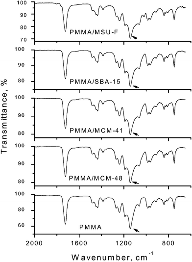 | ||
| Fig. 2 FTIR spectra of PMMA and PMMA/mesoporous silica nanocomposites containing 5.0% mesoporous silica made by in situemulsion polymerization and compression molding. The arrow points to the 1149 cm−1 C–C–O stretching band of PMMA which is slightly broadened in the nanocomposites due the overlapping Si–O stretching band of silica. | ||
3.3 Thermogravimetric analysis (TGA)
The thermogravimetric curves of PMMA and PMMA/mesoporous silica nanocomposites made by emulsion polymerization and compression molding are shown in Fig. 3. The thermal stabilities are improved upon the introduction of mesoporous silica into the PMMA matrix, regardless of pore size and structure of the mesoporous silica. As shown in Table 2, the temperature at 10% (T10) and 50% (T50) weight loss, the temperature at maximum weight loss rate (Tmax) and the end decomposition temperature (Tend) are all increased. For example, the T10, T50 and Tend values for the nanocomposite containing 5% MCM-48 silica increased by 10 °C, 17 °C and 25 °C, respectively, in comparison to pure PMMA. In the case of the pure polymer, which shows an additional small weight loss (<3 wt%) above 360 °C the Tend value was obtained by the intersection of the tangents to the maximum decomposition segment of the TGA curve and the small weight loss segment. The composite containing 5% MSU-F silica with the largest pore size of 24.8 nm provides the greatest in T10, T50 and Tend increases of 50 °C, 38 °C and 36 °C, respectively.42 | ||
| Fig. 3 Thermogravimetric (TG) analyses of PMMA and PMMA/mesoporous silica nanocomposites made by emulsion polymerization and compression molding; the upper panel provides the mass loss curves and the lower panel provides the corresponding derivative curves. | ||
| Mesoporous silica type | T 10 °C | T 50 °C | T max °C | T end °C |
|---|---|---|---|---|
| None | 299 | 333 | 297,323,350 | 360 |
| MCM-41 | 301 | 350 | 367 | 385 |
| MCM-48 | 309 | 350 | 306,363 | 385 |
| SBA-15 | 322 | 350 | 361 | 373 |
| MSU-F | 349 | 371 | 366 | 396 |
3.4 Differential scanning calorimetry (DSC)
The glass transition behavior of pure PMMA and PMMA/mesoporous silica nanocomposites as measured by DSC is described in Fig. 4. The glass transition temperature (Tg) of the pure PMMA is 107.3 °C, whereas all the PMMA nanocomposites show substantially higher Tg values. The PMMA/MCM-48, PMMA/SBA-15 and PMMA/MSU-F42 nanocomposites containing 5% mesoporous silica increases the Tg by 8.2, 9.0, and 9.3 °C, respectively, in comparison to pure PMMA. However, the Tg of the PMMA/MCM-41 nanocomposite is increased by only 4.6 °C. | ||
| Fig. 4 DSC curves of PMMA and PMMA/mesoporous silica nanocomposites by emulsion polymerization and compression molding. | ||
3.5 Dynamic mechanical analysis (DMA)
DMA and tan![[hair space]](https://www.rsc.org/images/entities/char_200a.gif) δ curves for PMMA and PMMA/mesoporous silica nanocomposites at 5% loading of mesoporous silica over the temperature range 30 to 180 °C are shown in Fig. 5. In comparison to the pristine polymer, all the PMMA/mesoporous silica nanocomposites exhibit higher storage modulus and Tg, as determined from the maximum in the tanδ plots). Moreover, the PMMA/MSU-F nanocomposite exhibits the greatest improvement in modulus. For example, the storage modulus for PMMA/MSU-F nanocomposite42 increases from 3584 MPa for PMMA to 4195 MPa for PMMA/MSU-F the nanocomposite at 50 °C (a 17% increase) and from 1408 MPa to 2528 MPa at 100 °C (an 80% increase). Also, the maximum in the tanδ plots shifts from 123.7 °C for pure PMMA to 139.4 °C for the PMMA/MSU-F nanocomposite.
δ curves for PMMA and PMMA/mesoporous silica nanocomposites at 5% loading of mesoporous silica over the temperature range 30 to 180 °C are shown in Fig. 5. In comparison to the pristine polymer, all the PMMA/mesoporous silica nanocomposites exhibit higher storage modulus and Tg, as determined from the maximum in the tanδ plots). Moreover, the PMMA/MSU-F nanocomposite exhibits the greatest improvement in modulus. For example, the storage modulus for PMMA/MSU-F nanocomposite42 increases from 3584 MPa for PMMA to 4195 MPa for PMMA/MSU-F the nanocomposite at 50 °C (a 17% increase) and from 1408 MPa to 2528 MPa at 100 °C (an 80% increase). Also, the maximum in the tanδ plots shifts from 123.7 °C for pure PMMA to 139.4 °C for the PMMA/MSU-F nanocomposite.
 | ||
| Fig. 5 DMA and tanδ curves of PMMA and PMMA/mesoporous silica nanocomposites by emulsion polymerization and compression molding. | ||
3.6 Transmission electron microscopy (TEM) images
The low and high magnification TEM images in Fig. 6 show the morphology of PMMA/mesoporous silica composites made by emulsion polymerization and compression molding. With the exception of composites made from MCM-48 silica with the smallest framework pore size, the higher magnification images clearly show the framework pore structure of the silica remains intact during the compression molding process. The domain sizes of the silica particles are in the range 200–1000 nm with SBA-15 exhibiting the smallest domain size of 200–300 nm (cf., Fig. 6e) and MCM-41 exhibiting the largest domain size of 500–1000 nm (cf., Fig. 6a). The low contrast between the silica walls and most of the framework pores is indicative of the penetration of PMMA into those framework pores under melt processing conditions.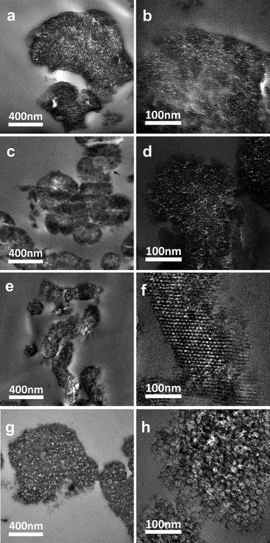 | ||
| Fig. 6 TEM images for thin sectioned specimens of (a) and (b) PMMA/MCM-41, (c) and (d) PMMA/MCM-48, (e) and (f) PMMA/SBA-15, and (g) and (h) PMMA/MSU-F composites. | ||
4. Discussion
Regardless of the framework structure and pore size of the silica component used to form the PMMA/mesoporous silica nanocomposites, the thermomechanical properties achieved at 5 wt% loadings are uniformly improved in comparison to the pure PMMApolymer. However, the performance properties are strongly correlated with the pore structure of the silicananoparticles. Mesoporous MSU-F silica with the largest pore size and pore volume shows the greatest enhancement in properties, whereas MCM-48 and 41 with the smallest framework pores provide the smallest benefits. For instance, the Tg values of the polymer and polymer nanocomposites (cf., Fig. 5) increase in the order of PMMA (123.7 °C) < PMMA/MCM-41 (126.0 °C) < PMMA/MCM-48 (127.6 °C) < PMMA/SBA-15 (135.0 °C) < PMMA/MSU-F (139.4 °C). The thermal stabilities (cf., Fig. 3) and storage moduli (cf., Fig. 5) also increase in the same order of composition. Thus, the pore size and pore volume of the silicananoparticles play a much more important role in determining the thermomechanical properties of the composites than other factors, such as surface area (largest for MCM-41 and -48) or particle domain size (smallest for SBA-15). However, for particles with approximately the same framework pore size and pore volume, as in the case of MCM-41 and -48 (cf., Table 1), the 3D pore structure of MCM-48 provides somewhat better benefits than the 1D pore structure of MCM-41.The confinement of the polymer in the mesopores of the silica particles undoubtedly plays a major role in the enhancement of the thermomechanical properties. On the basis of the framework pore volume of MSU-F silica, which has the largest pore volume of the mesostructures investigated, no more than 13.4% of the total PMMApolymer can be confined in the pores of the silica component of the composite at 5 wt% loading. Nevertheless the influence of the interphase phase region is sufficient to substantially restrict the segmental motions of the remaining unconfined polymer and boost Tg by as much as 9.3 °C, as determined by DSC. Even smaller fractions of polymer are confined to mesopores in the case of the composites made from MCM-41, MCM-48 and SBA-15 silicas with smaller framework volumes. Accordingly, composites made from these latter mesostructures provide corresponding lower levels of thermomechanical benefit.
The restricted segmental motions of the polymer chains most likely also contribute to the improved thermal stability of the polymer composites. The thermal degradation of pure PMMA in air is reported to occur in two main stages.46 The lower temperature stage involves chain unzipping starting at both the vinylidene end groups and the weaker head-to-head linkages, whereas the higher temperature process occurs through random scission of the polymer chains and the formation of peroxy radical intermediates.47 Pure PMMA clearly displays these two reaction stages, whereas the PMMA–mesoporous silica nanocomposites display mainly the second higher temperature decomposition stage (cf., Fig. 3). Analogous behavior is reported for the thermal decomposition of PMMA composites made from montmorillonite clay and synthetic zeolites. In these latter cases it is suggested that the radical intermediates involved in the decomposition process are trapped by the silicate phase, thus contributing to an improvement in thermal stability.48,49 The silica component of the composites formed in the present work also may play a radical scavenging role toward improving the thermal stability of the polymer matrix.
The observed improvements in thermomechanical properties for polymer/PMMA nanocomposites complement the findings of previous literature reports. For example, improved thermal stability was obtained for a PMMA/MCM-48 composite prepared by MMA bulk polymerization in the presence of mesoporous MCM-48.26 This was attributed to the interpenetrating organic polymer chain with an inorganic scaffold, and the improvement of interface interaction between the surface of inorganic particles and polymer resin.26 Also, a conducting polyaniline (PANI)/mesoporous aluminosilicate (Na–AlMCM-41) composite is reported to exhibit higher thermal stability because of the confinement effect in the channel system.25 The confinement of epoxypolymer in mesoporous SBA-15 silica also provided an improvement in thermal stability.19
With regard to the effect of polymer confinement on thermal properties, it is noteworthy that linear PS polymer chains in the pores of the zeolite 13X adopt a more extended, one dimensionally oriented conformation and thus does not exhibit a Tg value characteristic of a bulk polymer phase50 The confinement prevents the long-range motions that would otherwise occur at the normal glass transition. In addition, PMMA strands trapped within the 0.6–3.5 nm pores of MCM-41 and MCM-48 hosts do not show a characteristic glass transition behavior.37 In both cases, the polymer was confined entirely inside of the channels of the silica host and no polymer was found outside of the channel. In the present work only 5 wt% mesoporous silica was used to form the composites. Thus, the maximum amount of pore-confined polymer (13.4%) is realized for the MSU-F composite, assuming complete pore filling. Hence, interfacial interactions extend substantially into the bulk polymer, hindering segmental molecular motions and increasing the Tg of the matrix.
The improvements observed for the polymer composites of the present study complement earlier studies that report mesoporous silicas as polymer reinforcement agents. For example, MCM-41 nanoparticle dispersed in polypropylene provide some strengthening and toughening benefits.10 Also, mesoporous silica containing amino functional groups grafted to the pore walls improved both the thermal and the mechanical properties of a polyimide matrix.15,51 Furthermore, organofunctional mesoporous silica improves the mechanical properties of epoxypolymers.12,13 In most cases, however, the improvements are not comparable to those provided by organoclay reinforcing agents. Although these earlier studies provide insights into the benefits of mesoporous silica with different structure properties, they do not provide information relating composite properties to the pore structure of the silica. In this work, we demonstrate for the first time that the pore size of the mesoporous silica plays a significant role in the improvement of polymer properties.
5. Conclusion
The thermomechanical properties of PMMA/mesoporous silica nanocomposites are substantially influenced by the pore size and structure of the silica framework. In general, 3D framework structures and large mesopore sizes such as those provided by MSU-F and SBA-15 silicas are preferred over smaller and lower dimensional pore structures (e.g., MCM-41) because they provide a greater degree of polymer confinement and interfacial interactions that lead to improved thermal stability, higher glass transition temperatures and greater stiffness.Acknowledgements
Faai Zhang gratefully acknowledges the support of the State Scholarship Fund from the China Scholarship Council.References
- Y. S. Choi, M. H. Choi, K. H. Wang, S. O. Kim, Y. K. Kim and I. J. Chung, Macromolecules, 2001, 34, 8978–8985 CrossRef CAS.
- M. Z. Xu, Y. S. Choi, Y. K. Kim, K. H. Wang and I. J. Chung, Polymer, 2003, 44, 6387–6395 CrossRef CAS.
- Y. C. Chua and X. Lu, Langmuir, 2007, 23, 1701–1710 CrossRef.
- D. J. Voorn, W. Ming and A. M. van Herk, Macromolecules, 2006, 39, 2137–2143 CrossRef CAS.
- A. R. Mahdavian, M. Ashjari and A. B. Makoo, Eur. Polym. J., 2007, 43, 336–344 CrossRef CAS.
- C. Luo, X. Zuo, L. Wang, E. Wang, S. Song, J. Wang, C. Fan and Y. Cao, Nano Lett., 2008, 8, 4454–4458 CrossRef CAS.
- Y. Ma, P. L. Chiu, A. Serrano, S. R. Ali, A. M. Chen and H. He, J. Am. Chem. Soc., 2008, 130, 7921–7928 CrossRef CAS.
- J. L. Shi, Z. L. Hua and L. X. Zhang, J. Mater. Chem., 2004, 14, 795–806 RSC.
- H. Nakajima, K. Yamada, Y. Iseki, S. Hosoda, A. Hanai, Y. Oumi, T. Teranish and T. Sano, J. Polym. Sci., Part B: Polym. Phys., 2003, 41, 3324–3332 CrossRef CAS.
- N. Wang, M. T. Li and J. S. Zhang, Mater. Lett., 2005, 59, 2685–2688 CrossRef CAS.
- I. Park, H. G. Peng, D. W. Gidley, S. Q. Xue and T. J. Pinnavaia, Chem. Mater., 2006, 18, 650–656 CrossRef CAS.
- J. Jiao, X. Sun and T. J. Pinnavaia, Polymer, 2009, 50, 983–989 CrossRef CAS.
- J. Jiao, X. Sun and T. J. Pinnavaia, Adv. Funct. Mater., 2008, 18, 1067–1074 CrossRef CAS.
- J. He, Y. B. Shen, J. Yang, D. G. Evans and X. Duan, Chem. Mater., 2003, 15, 3894–3902 CrossRef CAS.
- C. F. Cheng, H. H. Cheng, P. W. Cheng and Y. J. Lee, Macromolecules, 2006, 39, 7583–7590 CrossRef CAS.
- M. J. MacLachlan, M. Ginzburg, N. Coombs, N. P. Raju, J. E. Greedan, G. A. Ozin and I. Manners, J. Am. Chem. Soc., 2000, 122, 3878–3891 CrossRef CAS.
- X. C. Dong, L. Wang, J. J. Wang, J. F. Zhou and T. X. Sun, J. Phys. Chem. B, 2006, 110, 9100–9104 CrossRef CAS.
- J. He, Y. B. Shen and D. G. Evans, Microporous Mesoporous Mater., 2008, 109, 73–83 CrossRef CAS.
- J. J. Lin and X. D. Wang, Eur. Polym. J., 2008, 44, 1414–1427 CrossRef CAS.
- M. Sasidharan, N. K. Mal and A. Bhaumik, J. Mater. Chem., 2007, 17, 278–283 RSC.
- Y. Jung, S. Kimb, S. J. Park and J. M. Kim, Colloids Surf., A, 2008, 313–314, 162–166 CrossRef.
- K. Maeda, K. Ichinose, T. Yamazaki and T. Suzuki, Microporous Mesoporous Mater., 2008, 112, 603–611 CrossRef CAS.
- I. Park and T. J. Pinnavaia, Adv. Funct. Mater., 2007, 17, 2835–2841 CrossRef CAS.
- M. Fujiwara, K. Kojima, Y. Tanaka and R. Nomura, J. Mater. Chem., 2004, 14, 1195–1202 RSC.
- O. A. Anunziata, M. B. G. Costa and R. D. Sanchez, J. Colloid Interface Sci., 2005, 292, 509–516 CrossRef CAS.
- M. T. Run, S. Z. Wu, D. Y. Zhang and G. Wu, Mater. Chem. Phys., 2007, 105, 341–347 CrossRef CAS.
- A. G. Pattantyus-Abraham and M. O. Wolf, Chem. Mater., 2004, 16, 2180–2186 CrossRef CAS.
- C. G. Wu and T. Bein, Science, 1994, 264, 1757–1759 CrossRef CAS.
- Q. L. Cheng, V. Pavlinek, C. Z. Li, A. Lengalova, Y. He and P. Saha, Mater. Chem. Phys., 2006, 98, 504–508 CrossRef CAS.
- M. Nandi, R. Gangopadhyay and A. Bhaumik, Microporous Mesoporous Mater., 2008, 109, 239–247 CrossRef CAS.
- T. Uemura, S. Horike, K. Kitagawa, M. Mizuno, K. Endo, S. Bracco, A. Comotti, P. Sozzani, M. Nagaoka and S. Kitagawa, J. Am. Chem. Soc., 2008, 130, 6781–6788 CrossRef CAS.
- P. Valsesia, M. Beretta, S. Bracco, A. Comotti and P. Sozzani, J. Mater. Chem., 2008, 18, 5511–5517 RSC.
- M. Lenarda, G. Chessa, E. Moretti, S. Polizzi, L. Storaro and A. Talon, J. Mater. Sci., 2006, 41, 6305–6312 CrossRef CAS.
- J. S. Jang, B. Lim, J. Lee and T. Hyeon, Chem. Commun., 2001, 83–84 RSC.
- X. F. Ni, Z. Q. Shen and H. Yasuda, Chin. Chem. Lett., 2001, 12(9), 821–822 CAS.
- K. Moller, T. Bein and R. X. Fischer, Chem. Mater., 1999, 11, 665–673 CrossRef CAS.
- K. Moller, T. Bein and R. X. Fischer, Chem. Mater., 1998, 10, 1841–1852 CrossRef CAS.
- S. M. Ng, S. Ogino, T. Aida, K. A. Koyano and T. Tatsumi, Macromol. Rapid Commun., 1997, 18, 991–996 CrossRef CAS.
- K. Kageyama, J. Tamazawa and T. Aida, Science, 1999, 285, 2113–2115 CrossRef CAS.
- B. S. Tian and C. Yang, Acta Chim. Sinica, 2008, 66(5), 505–510 Search PubMed.
- L. Wei and Y. Zhang, J. Polym. Sci., Part A: Polym. Chem., 2009, 47, 1393–1402 CrossRef CAS.
- F. A. Zhang, D. K. Lee and T. J. Pinnavaia, Polymer, 2009, 50, 4768–4774 CrossRef CAS.
- C. T. Kresge, M. E. Leonowicz, W. J. Roth, J. C. Vartuli and J. S. Beck, Nature, 1992, 359, 710–712 CrossRef CAS.
- J. C. Vartuli, K. D. Schmitt, C. T. Kresge, W. J. Roth, M. E. Leonowicz, S. B. McCullen, S. D. Hellring, J. S. Beck, J. L. Schlenker, D. H. Olson and E. W. Sheppard, Chem. Mater., 1994, 6, 2317–2326 CrossRef CAS.
- D. Y. Zhao, J. L. Feng, Q. S. Huo, N. Melosh, G. H. Fredrickson, B. F. Chmelka and G. D. Stucky, Science, 1998, 279, 548–552 CrossRef CAS.
- T. Hirata, T. Kashiwagi and J. E. Brown, Macromolecules, 1985, 18, 1410–1418 CrossRef CAS.
- T. Kashiwagi, A. Inaba, J. E. Brown, K. Hatada, T. Kitayama and E. Masuda, Macromolecules, 1986, 19, 2160–2168 CrossRef CAS.
- D. H. Solomon and J. D. Swift, J. Appl. Polym. Sci., 1967, 11, 2567 CrossRef CAS.
- K. J. Hwang and D. S. Kim, J. Appl. Polym. Sci., 2008, 110, 2957–2960 CrossRef CAS.
- H. L. Frisch and J. E. Mark, Chem. Mater., 1996, 8, 1735–1738 CrossRef CAS.
- C. K. Min, T. B. Wu, W. T. Yang and C. L. Chen, Compos. Sci. Technol., 2008, 68, 1570–1578 CrossRef CAS.
| This journal is © The Royal Society of Chemistry 2010 |