Electrodeposition of thermally stable gold and silver nanoparticle ensembles through a thin alumina nanomask
Yukina
Takahashi
a and
Tetsu
Tatsuma
*ab
aInstitute of Industrial Science, The University of Tokyo, Komaba, Meguro-ku, Tokyo, 153-8505, Japan
bPRESTO, Japan Science and Technology Agency (JST), Honcho, Kawaguchi-shi, Saitama, 332-0012, Japan
First published on 29th June 2010
Abstract
Hemispheric gold or silver nanoparticle (Au and AgNP) ensembles were electrodeposited on a smooth ITO electrode through a thin Al2O3 nanomask. The nanomask reduced the deviation in the particle size and interparticle distance. The absorption peak based on localized surface plasmon resonance (LSPR) of the AuNP ensemble redshifted with increasing environmental refractive index, suggesting that the ensemble would be used as a LSPR sensor for chemical analysis and bioanalysis. The Al2O3 nanomask prevented the Au and AgNPs from thermal coalescence even at 500 °C, and consequently, it improved thermal stabilities of nanoparticle ensembles. The ensembles exhibit LSPR-based absorption peak in the visible region, even after annealing. The nanomask allowed AgNPs, which are thermally and chemically less stable than AuNPs, to be coated with sintered TiO2. The ITO/AgNP/TiO2 electrode thus obtained functions as a photocathode on the basis of photoinduced electron transfer from silver nanoparticles to TiO2.
1. Introduction
Arrays and ensembles of metal nanoparticles, such as gold and silver, prepared on solid substrates have been studied in various fields.1–8 Ensembles of metal nanoparticles can be used as nanoelectrode ensembles, which are characterized by low non-Faradaic currents, and those are applied to electrochemical analyses with high signal/background and signal/noise ratios.9,10 On the other hand, nanoparticles of noble metals are known to absorb light due to localized surface plasmon resonance (LSPR), and the resonance wavelength redshifts with an increasing local dielectric constant. The nanoparticle ensembles are therefore applied to chemical analysis and bioanalysis as LSPR sensors.11–13 We have recently developed LSPR-based photoelectrodes by coupling gold nanoparticle (AuNP) ensembles with TiO2. The photoelectrodes give photoelectrochemical responses on the basis of photoinduced charge separation at the AuNP–TiO2 interface.14–18There are several methods to prepare nanoparticle arrays and ensembles. Although nanolithography such as electron beam lithography provides finely tailored nanoparticle arrays,19,20 it is not for large area fabrication due to its slow and expensive processes. On the other hand, deposition of metal nanoparticles in a nanoporous template is a more convenient and less expensive method. Many different materials and preparation methods have been employed to fabricate templates with controlled pore size and interpore spacing.1–6 Masuda et al.1–3 prepared highly ordered deep nanowell arrays on Al2O3 films by anodic oxidation of aluminium. They studied plasmon resonance properties of AuNPs deposited in the templates. Thus far, most of the nanoporous templates are around 100–500 nm thick.5 Deposited metal nanoparticles are therefore nanowires or nanorods in general, of which plasmon resonance wavelengths are mostly in a far red or near infrared region. This could be a drawback in application to LSPR sensors and LSPR photoelectrodes. In addition, if the nanoparticles are deposited at the bottom of the deep nanowells, the template must be removed for the LSPR applications, because otherwise the template hinders the contact between the nanoparticles and a sample solution or electrolyte.
Grosso et al.5,6 prepared thin metal oxide (TiO2, Al2O3 and ZrO2) films of <10 nm thickness with nanopores of <50 nm diameter and spacing. It is expected that less anisotropic metal nanoparticles would be electrodeposited on an electrode through the thin nanoporous Al2O3 film as a nanomask. Since the deposited nanoparticles are anticipated to be resonant in the visible region and highly exposed and accessible, the resultant nanoparticle ensembles would be suitable to LSPR sensors and photoelectrodes without removal of the nanomask. In addition, the thin nanomask would prevent the deposited nanoparticles from coalescing into larger ones even when the ensemble is heated. Although nanosphere lithography7 is also a convenient method to prepare size-controlled nanoparticle arrays, the particles in the arrays would coalesce with each other at high temperatures. Thermal stability is an essential characteristic for a nanoparticle ensemble when it is covered with a semiconductor layer and annealed to prepare, for instance, an ITO/AuNP/TiO2 photoelectrode.18 By using the present nanomask, silver nanoparticles (AgNPs), which are thermally and chemically less stable than AuNPs, would also be applicable to LSPR-based photoelectrodes. It would be possible to develop cost-effective photovoltaic cells. In this study, we electrodeposited AuNPs or AgNPs through an Al2O3 nanomask on an ITO electrode and examined their plasmon resonance properties and photoelectrochemical responses.
2. Experimental
A smooth indium tin oxide (ITO) coated glass plate (Ra = ca. 0.3 nm), which was purchased from Kuramoto Co., Ltd., was cleaned by sonication in a detergent solution for 1 h. The substrate was rinsed with water and wiped dry with a tissue soaked with ethanol just before dip-coating. Al2O3 nanomasks were prepared according to literature.6 A solution consisting of 0.16 g of PS-b-PEO (polystyrene-b-polyethyleneoxide, P4750-SEO, Polymersource; Mw PS = 40![[thin space (1/6-em)]](https://www.rsc.org/images/entities/char_2009.gif) 000 g mol−1, Mw PEO = 36000 g mol−1), 18 g of ethanol and 22 g of tetrahydrofuran was added to another solution consisting of 1.0 g of AlCl3·6H2O and 1.34 g of 15 wt% NH3 aqueous solution that had been aged for 2 weeks. Dip-coating was carried out at a constant withdrawal rate, 0.7 mm s−1, at 22% relative humidity at room temperature, followed by annealing at 500 °C for 1 h.
000 g mol−1, Mw PEO = 36000 g mol−1), 18 g of ethanol and 22 g of tetrahydrofuran was added to another solution consisting of 1.0 g of AlCl3·6H2O and 1.34 g of 15 wt% NH3 aqueous solution that had been aged for 2 weeks. Dip-coating was carried out at a constant withdrawal rate, 0.7 mm s−1, at 22% relative humidity at room temperature, followed by annealing at 500 °C for 1 h.
Gold nanoparticles (AuNPs) were electrodeposited cathodically on the ITO electrode coated with the Al2O3 nanomask at −0.5 to −2.0 V for 10 or 20 s from a 2 mM NaAuCl4 aqueous solution containing 0.5 M H2SO4 and 0.125 mM L-cysteine under nitrogen atmosphere.21 The electrode potential was controlled with a digital potentiostat (1280Z, Solartron). A Ag|AgCl and a Pt wire were used as the reference and counter electrodes, respectively. Electrodeposition of silver nanoparticles (AgNPs) on the nanomask-coated ITO electrode was performed at −2.0 V for 60 s from a 2 mM AgNO3 aqueous solution containing 0.5 M H2SO4 under nitrogen atmosphere using a Ag|Ag+ (not to precipitate AgCl in the solution) and a Pt wire as the reference and counter electrodes, respectively. If necessary, TiO2 coating was carried out by a spray-pyrolysis technique,22 in which a solution containing 0.38 M titanium diisopropoxide bis(acetylacetonate) in 2-propanol was sprayed for 1 s with 0.12 MPa nitrogen gas to the substrate kept at 500 °C. This coating was repeated 8 times at 1 min intervals. The temperature was kept for another 0.5 h in air after the spray processes.
%Absorption spectra were obtained by subtracting transmittance and reflectance from 100% by using a UV-Vis spectrophotometer (V-670, JASCO) with an integrating sphere, so as to eliminate effects of scattering and reflection. For measurements of spectrophotometric responses of an electrode with AuNPs to refractive index, liquids of different refractive indices (water (1.33), 60 wt% aqueous glucose solution (1.42),23 toluene (1.496) and diiodomethane (1.73)) were used. After each measurement the electrode was rinsed thoroughly with distilled water and dried. Surface morphology of the samples was observed by field emission scanning electron microscopy (FE-SEM; JSM-7500A, JEOL) at an acceleration voltage of 15.0 kV and atomic force microscopy (AFM; SP-400, SII Nanotechnology) in tapping mode with driving frequency of 110–150 kHz at a scan rate of ∼0.4 Hz by using a silicon cantilever (SI-DF20, SII Nanotechnology) with a normal spring constant of 15 N m−1 and tip curvature radius of 10 nm. The particle and hole sizes were calculated from AFM images taking the tip size into account using “morphology filter” (SII Nanotechnology). Photoelectrochemical measurements were carried out using a sandwich cell with the photoelectrode and a gold-sputtered ITO counter electrode. The gap between the electrodes (0.5 mm) was filled with a N2-saturated aqueous electrolyte containing 1 M Na2SO4, 0.1 M FeSO4 and 0.025 M Fe2(SO4)3. The visible light source was a Xe lamp (LA-251Xe, Hayashi Tokei) with a UV (λ < 420 nm) cut-off filter.
3. Results and discussion
3.1 Electrodeposition of AuNP ensembles through the Al2O3 nanomask
An Al2O3 nanomask was prepared according to literature6 on a smooth ITO electrode. Fig. 1a and b show AFM and SEM images of the surface and cross-section of the prepared nanomask. The depth and the diameter of the pores were ca. 8.6 nm and 34.0 ± 0.2 nm, respectively (mean ± standard error, n = 296). The density of the pores was 3.0 × 102 µm−2.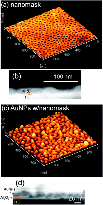 | ||
| Fig. 1 (a) AFM surface image and (b) SEM cross-sectional image of the Al2O3 nanomask on a smooth ITO electrode and (c) AFM and (d) SEM images of AuNPs electrodeposited at −2.0 V vs. Ag|AgCl for 10 s through the nanomask. | ||
Gold nanoparticles (AuNPs) were electrodeposited on the smooth ITO electrodes with and without the Al2O3 nanomask at −0.5 V vs. Ag|AgCl for 20 s. At this potential, nucleation of gold is superior to growth of gold nuclei,21 so that AuNPs deposit even on a bare electrode without the nanomask. The size and the density of AuNPs deposited without the nanomask were 38.7 ± 1.0 nm (n = 214) and 3.6 × 102 µm−2, respectively (Fig. 2a). On the other hand, more anisotropic and fewer AuNPs (1.6 × 102 µm−2) were deposited on the nanomask-coated ITO at the same potential. The density of the nanoparticles was much lower than that of the pores. Ratio of the number of the AuNPs deposited through the nanomask to that of the nanoparticles deposited on a bare ITO is 44%, which is comparable to ratio of the total area of the pores to the overall substrate area, 30%. These results suggest that the number of nuclei is roughly in proportion to the active electrode area and that nucleation density must be raised to increase the number of particles deposited through the nanomask.
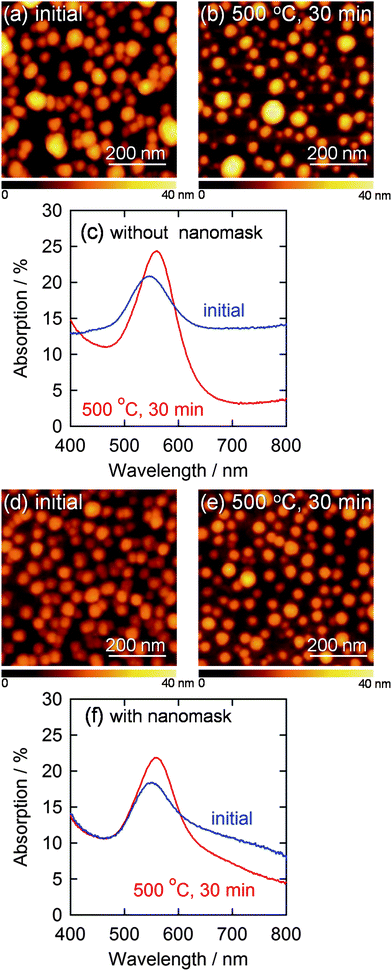 | ||
| Fig. 2 AFM images of AuNPs electrodeposited on a bare ITO at −0.5 V vs. Ag|AgCl for 20 s (a) before and (b) after annealing at 500 °C for 30 min and (c) corresponding visible absorption spectra. AFM images of AuNPs deposited through the Al2O3 nanomask at −2.0 V vs. Ag|AgCl for 10 s (d) before and (e) after annealing at 500 °C for 30 min are also shown with (f) corresponding visible absorption spectra. | ||
We therefore deposited AuNPs through the nanomask at more negative potentials, since a higher overpotential (e.g., more negative potential) promotes nucleation of nanoparticles. If the deposition was performed at −2.0 V vs. Ag|AgCl for 10 s, the size and the density of the resultant nanoparticles were 33.5 ± 0.6 nm (n = 302) and 3.0 × 102 µm−2, respectively (Fig. 2d). These values are in good agreement with the size (34.0 nm) and the density (3.0 × 102 µm−2) of the pores in the nanomask. Incidentally, all the nanoparticles are in the pores since Al2O3 is insulating. Ratio of the standard error to the average particle diameter (0.6/33.5 = 0.018) is smaller than that for the AuNPs deposited on a bare ITO at −0.5 V vs. Ag|AgCl for 20 s (1.0/38.7 = 0.030), suggesting that the nanomask suppresses the deviation of the particle diameter. The diameter histograms of the AuNPs shown in Fig. 3 confirm the trend. The AFM and SEM images (Fig. 1c and d) show that the electrodeposited AuNPs are hemispheric and their height (ca. 20 nm) is greater than the depth of the pores (8.6 nm). In the following experiments, characteristics of the AuNPs deposited at −2.0 V vs. Ag|AgCl for 10 s through the Al2O3 nanomask are compared with those of the AuNPs deposited at −0.5 V vs. Ag|AgCl for 20 s on a bare ITO.
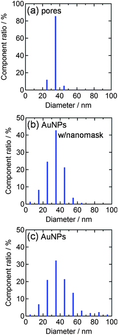 | ||
| Fig. 3 Diameter histograms obtained from AFM images (1 µm2 each) for (a) nanopores of the Al2O3 nanomask (3.0 × 102 µm−2), (b) AuNPs deposited through the nanomask at −2.0 V vs. Ag|AgCl for 10 s (3.0 × 102 µm−2) and (c) AuNPs deposited on a bare ITO at −0.5 V vs. Ag|AgCl for 20 s (3.6 × 102 µm−2). | ||
The AuNPs deposited through the nanomask exhibited an absorption peak due to localized surface plasmon resonance (LSPR) at 559 nm (Fig. 2f). The peak overlaps with interband transitions of gold, absorption of which monotonically increases as the wavelength decreases from about 500 nm. Here we use %absorption spectra instead of absorbance spectra, to eliminate the effects of scattering and reflection (see Experimental section). Although AuNPs deposited on a bare ITO electrode without the nanomask exhibited a similar peak intensity, absorption was larger in the longer wavelength region (≥600 nm) (Fig. 2c). This absorption could be explained in terms of interparticle plasmon coupling24,25 between closely deposited particles. In the case of the electrodeposition through the nanomask, however, the nanoparticles are not located randomly, but placed in the pores, which are apart from each other,6 resulting in the suppressed plasmon coupling. On the basis of these results, we conclude that the Al2O3 nanomask allows to regulate the size and interparticle distance of electrodeposited AuNPs to obtain a well-distributed AuNP ensemble.
3.2 Thermal stability of the AuNP ensemble
Thermal stability is an essential characteristic for a AuNP ensemble when it is covered with a semiconductor layer and annealed to prepare a LSPR-based photoelectrode for photoelectrochemical devices such as photovoltaic cells.18 During annealing at 500 °C for 30 min, some of the AuNPs without the nanomask coalesced into larger ones (Fig. 2b), while the AuNPs with the nanomask showed no significant changes in morphology (Fig. 2e). This indicates that the nanomask inhibits thermal fusion of AuNPs on the substrate. Some of the annealed AuNPs are smaller in the lateral diameter than the as-deposited ones (i.e. the average lateral diameter of the bottom 10% AuNPs decreased from 22 nm to 14 nm), likely because the hemispherical particles become more spherical at high temperatures due to surface tension.The difference is also reflected by the spectroscopic changes shown in Fig. 2c and f; the AuNPs without the nanomask gave rise to larger spectral changes, i.e. the larger redshift and the greater drop in the absorption at longer wavelengths. These changes should be chiefly ascribed to growth of the particles26–29 and an increase in the interparticle distance,24,25 respectively, due to the coalescence of the AuNPs.
3.3 Response of the AuNP ensemble to refractive index changes
It is known that the plasmon absorption peak redshifts with increasing environmental refractive index.30,31 This property has been exploited for LSPR sensing, which is applicable to biosensors and chemical sensors.11–13 Thus, we measured the peak wavelengths of the prepared AuNP ensemble with the nanomask in some liquids with different refractive indices (Fig. 4). As a result, the peak wavelength (λmax) increased with the refractive index (n). The sensitivities Δλmax/Δn of the AuNP ensembles with and without the nanomask were 46 and 58 nm RIU−1 (refractive index unit), respectively. The lower sensitivity of the ensemble with the nanomask can be explained in terms of lower exposure to liquids of the partially buried AuNPs in the nanomask. However, the AuNP ensemble can be applied to LSPR sensors without removal of the nanomask. No degradation of the AuNPs was observed spectrophotometrically after each experiment. Incidentally, the average change in the absorbance in each measurement was less than 1% for the AuNPs with the nanomask.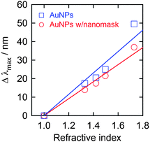 | ||
| Fig. 4 LSPR-based absorption peak shift (Δλmax = λmax(solvent) − λmax(air)) of AuNPs deposited on ITO with and without the Al2O3 nanomask (−0.5 V vs. Ag|AgCl for 20 s and −2.0 V vs. Ag|AgCl for 10 s, respectively) upon immersion in liquids with different refractive indices (water (1.33), 60 wt% aqueous glucose solution (1.42), toluene (1.496) and diiodomethane (1.73)). | ||
3.4 Electrodeposition of AgNP ensembles through the Al2O3 nanomask
We also tried to electrodeposit silver nanoparticles (AgNPs) through the Al2O3 nanomask on an ITO electrode at various potentials between −0.5 and −2.0 V vs. Ag|Ag+ from a 2 mM AgNO3 aqueous solution containing 0.5 M H2SO4 under nitrogen atmosphere. The electrode after electrodeposition at −0.5 V vs. Ag|Ag+ for 60 s exhibited no obvious absorption peak in the visible region. On the other hand, a brown sample with an absorption peak at 400 nm due to LSPR was obtained by electrodeposition at −2.0 V vs. Ag|Ag+ for 60 s. It was revealed by AFM that the size and anisotropy of AgNPs decreased as the applied potential shifted negatively, as was the case for AuNPs.21 A high overpotential promotes generation of a number of NP seeds, resulting in poor development in the particle size and anisotropy.3.5 Thermal stability of the AgNP ensemble
The AgNPs electrodeposited at −2.0 V vs. Ag|Ag+ for 60 s through the nanomask was annealed at 500 °C for 0.5 h for examination of their thermal stability (Fig. 5). It is expected that the morphology and optical properties of AgNPs are more sensitive to temperature changes than those of AuNPs because melting point of bulk silver (961 °C) is lower than that of gold (1063 °C) and Tamman temperature, at which atoms from the bulk may exhibit mobility, of silver (344 °C) is also lower than that of gold (395 °C).32 In addition, particle size of AgNPs effects more significantly on the plasmon peak shift than that of AuNPs.29,33 Actually, AgNPs electrodeposited on an ITO electrode without the nanomask extensively merged with each other, and the plasmon absorption peak in the visible region almost completely disappeared after annealing (Fig. 5c). On the other hand, AgNPs electrodeposited through the nanomask showed no dramatic changes in the morphology and in absorption spectrum in the visible region (Fig. 5f). Therefore, AgNPs can be covered with a dense and stable inorganic layer prepared by sintering, so that AgNPs, which are chemically less stable than AuNPs, would be protected from corrosive solutions.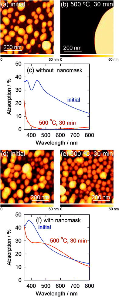 | ||
| Fig. 5 AFM images of AgNPs electrodeposited on a bare ITO at −1.5 V vs. Ag|Ag+ for 60 s (a) before and (b) after annealing at 500 °C for 30 min and (c) corresponding visible absorption spectra. AFM images of AgNPs deposited through the Al2O3 nanomask at −2.0 V vs. Ag|Ag+ for 60 s (d) before and (e) after annealing at 500 °C for 30 min are also shown with (f) corresponding visible absorption spectra. | ||
3.6 Photoelectrochemical responses of the TiO2-coated AgNP ensemble
We also examined photoelectrochemical responses of the AgNP ensemble covered with TiO2 (ITO/AgNP/TiO2). We have previously reported that TiO2 electrodes on which AuNPs were deposited (ITO/TiO2/AuNP)15 and TiO2-coated AuNP electrodes (ITO/AuNP/TiO2)18 showed anodic and cathodic photocurrents, respectively, under visible light irradiation on the basis of LSPR-based electron transfer from photoexcited AuNPs to TiO2. If the AuNPs can be replaced with AgNPs, more cost-effective and wide-wavelength-range photoelectrodes can be developed. However, since AgNPs are chemically and thermally less stable than AuNPs, the replacement has been difficult. ITO/TiO2/AgNP electrodes are short-lived because AgNPs on TiO2 are easily oxidized and dissolved in electrolyte under visible light by the LSPR-based electron transfer from AgNPs to TiO2.34,35 The oxidative dissolution would be prevented by coating the AgNPs with a dense TiO2 film to obtain ITO/AgNP/TiO2 electrodes. When AgNPs are covered with TiO2, however, their LSPR peak disappears from the visible light range because the AgNPs coalesce with each other into huge particles during the sintering process.However, the present, thermally stable AgNP ensemble with the nanomask retained sufficient light absorption in the visible range even after coating with a sintered TiO2 layer. The obtained ITO/AgNP/TiO2 electrode exhibited cathodic photocurrents under visible light as shown in Fig. 6a. The cathodic action spectrum of incident photon to current conversion efficiency (IPCE) was in relatively good agreement with an absorption spectrum of an annealed AgNP ensemble (Fig. 6b). These results indicate that AgNPs can also be used for stable photoelectrodes. The maximum IPCE value is 2.8-fold lower than that for the ITO/AuNP/TiO2 electrode,18 possibly because the AgNPs have broader size and shape distributions and broader absorption band than the AuNPs. Since non-resonant AgNPs might short-circuit between the ITO and TiO2, narrowing the size and shape distributions would improve the IPCE value. In any event, the present system would be promising from an economic point of view.
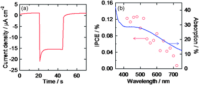 | ||
| Fig. 6 (a) Photocurrent under visible light irradiation (>420 nm, 100 mW cm−2) and (b) cathodic action spectrum under monochromatic light (5 × 10¹⁴ photons cm−2 s−1) of the ITO/AgNP/TiO2 electrode with the Al2O3 nanomask in an aqueous solution containing 0.1 M FeSO4, 0.025 M Fe2(SO4)3 and 1 M Na2SO4. Absorption spectrum of an ITO/AgNP electrode after annealing is also shown in (b). | ||
4. Conclusions
The Al2O3 nanomask allows to regulate size and interparticle distance of electrodeposited AuNPs and AgNPs. In addition, the nanomask enhances the thermal stabilities of the nanoparticle ensembles by preventing the nanoparticles from coalescing even at 500 °C. The prepared AuNP ensemble with the Al2O3 nanomask can be used as a LSPR sensor for refractive index, in which a good contact between nanoparticles and a test solution is necessary. In addition, the TiO2 coated AgNP ensemble with the Al2O3 nanomask on an ITO electrode can be used as a LSPR-based photocathode under visible light irradiation.Acknowledgements
The present work was supported in part by KAKENHI (Grant-in-Aid for Scientific Research, No. 19049008) on Priority Area “Strong Photons-Molecules Coupling Fields (No. 470)” from MEXT, JAPAN, JST and Asahi Glass Co., Ltd.References
- H. Masuda and M. Satoh, Jpn. J. Appl. Phys., 1996, 35, L126 CrossRef CAS.
- F. Matsumoto, M. Ishikawa, K. Nishio and H. Masuda, Chem. Lett., 2005, 508 CrossRef CAS.
- T. Kondo, F. Matsumoto, K. Nishio and H. Masuda, Chem. Lett., 2008, 466 CrossRef CAS.
- C. Langhammer, Z. Yuan, I. Zorić and B. Kasemo, Nano Lett., 2006, 6, 833 CrossRef CAS.
- C. Sanchez, C. Boissière, D. Grosso, C. Laberty and L. Nicole, Chem. Mater., 2008, 20, 682 CrossRef CAS.
- M. Kuemmel, J. Allouche, L. Nicole, C. Boissière, C. Laberty, H. Amentisch, C. Sanchez and D. Grosso, Chem. Mater., 2007, 19, 3717 CrossRef CAS.
- T. R. Jensen, M. D. Malinsky, C. L. Haynes and R. P. Van Duyne, J. Phys. Chem. B, 2000, 104, 10549 CrossRef CAS.
- C. A. Foss, Jr, G. L. Hornyak, J. A. Stockert and C. R. Martin, J. Phys. Chem., 1992, 96, 7497 CrossRef.
- C. R. Martin, Science, 1994, 266, 1961 CrossRef CAS.
- S. Guo and E. Wang, Anal. Chim. Acta, 2007, 598, 181 CrossRef CAS.
- N. Nath and A. Chikoti, Anal. Chem., 2002, 74, 504 CrossRef CAS.
- A. J. Haes, S. Zou, G. C. Schatz and R. P. Van Duyne, J. Phys. Chem. B, 2004, 108, 109 CrossRef CAS.
- C. Guo, P. Boullanger, L. Jiang and T. Liu, Biosens. Bioelectron., 2007, 22, 1830 CrossRef CAS.
- Y. Tian and T. Tatsuma, Chem. Commun., 2004, 1810 RSC.
- Y. Tian and T. Tatsuma, J. Am. Chem. Soc., 2005, 127, 7632 CrossRef CAS.
- K. Yu, Y. Tian and T. Tatsuma, Phys. Chem. Chem. Phys., 2006, 8, 5417 RSC.
- K. Yu, N. Sakai and T. Tatsuma, Electrochemistry, 2008, 76, 161 CAS.
- N. Sakai, Y. Fujiwara, Y. Takahashi and T. Tatsuma, ChemPhysChem, 2009, 10, 766 CrossRef CAS.
- B. Lamprecht, G. Schider, R. T. Lechner, H. Ditlbacher, J. R. Krenn, A. Leitner and F. R. Aussengg, Phys. Rev. Lett., 2000, 84, 4721 CrossRef CAS.
- W. Gotschy, K. Vonmetz, A. Leitner and F. R. Aussenegg, Appl. Phys. B: Lasers Opt., 1996, 63, 381 CAS.
- N. Sakai, Y. Fujiwara, M. Arai, K. Yu and T. Tatsuma, J. Electroanal. Chem., 2009, 628, 7 CrossRef CAS.
- Y. Tachibana, K. Umekita, Y. Otsuka and S. Kuwabata, J. Phys. D: Appl. Phys., 2008, 41, 102002 CrossRef.
- G. Steiner, M. T. Pham, Ch. Kuhne and R. Salzer, Fresenius’ J. Anal. Chem., 1998, 362, 9 CrossRef CAS.
- M. Gluodenis and C. A. Foss, Jr, J. Phys. Chem. B, 2002, 106, 9484 CrossRef CAS.
- M. Futamata, Y. Maruyama and M. Ishikawa, J. Phys. Chem. B, 2003, 107, 7607 CrossRef CAS.
- P. K. Jain, K. S. Lee, I. H. El-sayed and M. A. El-sayed, J. Phys. Chem. B, 2006, 110, 7238 CrossRef CAS.
- S. Link and M. A. El-Sayed, J. Phys. Chem. B, 1999, 103, 8410 CrossRef CAS.
- L. M. Lis-Marzan, Langmuir, 2006, 22, 32 CrossRef CAS.
- P. N. Njoki, I. S. Lim, D. Mott, H. Park, B. Khan, S. Mishra, R. Sujakumar, J. Luo and C. Zhong, J. Phys. Chem. C, 2007, 111, 14664 CrossRef CAS.
- L. B. Scaffardi and J. O. Tocho, Nanotechnology, 2006, 17, 1309 CrossRef CAS.
- J. J. Mock, D. R. Smith and S. Schultz, Nano Lett., 2003, 3, 485 CrossRef CAS.
- J. A. Moulijn, A. E. van Diepen and F. Kapteijn, Appl. Catal., A, 2001, 212, 3 CrossRef CAS.
- D. D. Evanoff, Jr and G. Chumanov, J. Phys. Chem. B, 2004, 108, 13948 CrossRef.
- Y. Ohko, T. Tatsuma, T. Fujii, K. Naoi, C. Niwa, Y. Kubota and A. Fujishima, Nat. Mater., 2003, 2, 29 CrossRef CAS.
- K. Naoi, Y. Ohko and T. Tatsuma, J. Am. Chem. Soc., 2004, 126, 3664 CrossRef CAS.
| This journal is © The Royal Society of Chemistry 2010 |