Crystalline nanoporous metal oxide thin films by post-synthetic hydrothermal transformation: SnO2 and TiO2†
Shaofeng
Shao
ab,
Momtchil
Dimitrov
bc,
Naijia
Guan
a and
Ralf
Köhn
*b
aLab of Functional Polymer Materials, College of Chemistry, Nankai University, Tianjin, People's Republic of China
bDepartment of Chemistry and Biochemistry, University of Munich, Butenandtstraße 11, 82377, Munich, Germany. E-mail: ralf.koehn@cup.uni-muenchen.de; Fax: +49 (0)89-218077622; Tel: +49 (0)89-218077808
cInstitute of Organic Chemistry, Bulgarian Academy of Sciences, Sofia, Bulgaria
First published on 15th July 2010
Abstract
Nanostructured and nanoporous metal oxide thin films are rarely accessible by standard synthetic approaches but highly desired for many applications, e.g. as electrodes, transparent conducting coatings, sensors or surface catalysts. Template based sol–gel chemistry combined with post-synthetic hydrothermal treatment allows now the synthesis of nanocrystalline mesostructured porous thin films of metal oxides, e.g. tin oxide and titania. Even in cases where the crystallization cannot be induced highly stable thin films can be achieved, e.g. niobium oxide thin films. We demonstrate how the size of the nanocrystallites influences and stabilizes the mesostructure at temperatures as low as 100 °C and thereby in the case of titania or tin dioxide even prevents it from deterioration at higher temperatures up to 400–600 °C.
Since the first reports of mesostructured and nanoporous silica thin films by evaporation-induced self-assembly (EISA)1–3 nanoporous metal or metalloid oxide materials have gained significant attention due to their characteristic sorption, catalytic, electronic, and optical properties which allows their application in adsorption, ion-exchange, catalysis, sensing, electronics, or host–guest chemistry.4–7 The structure directing agents (SDAs) induce the formation of the mesostructure and upon thermal removal generate nanopores. They are usually commercially available surfactants, e.g. neutral block-copolymers (Pluronics), poly(oxyethylene)alkyl ethers (Brij), or alkyltrimethylammonium halides (CTAB, CTAC).8–11 For the generation of nanoporous metal oxide thin films spin or dip coating is employed allowing the inorganic precursor to arrange and condense around the SDA replicating their structure in a cooperative mechanism.1,9
While the first synthetic attempts were focused on silica materials1,2,12,13 the procedures were successfully transferred to metal oxides to generate mesostructured metal oxide thin films.14,15 However, due to the flexibility of the amorphous pore walls in the silica phases the transformation was not completely successful. Many metal oxides do not even result in mesostructured thin films upon synthesis except with special templates. In cases where a mesostructure can be obtained the structure is not necessarily stable for the transformation into a mesoporous thin film. Most metal oxides crystallize during the thermal removal of the template or degrade upon extraction procedures. The reason is the lacking support of the structure director after its removal. The strong forces that occur during the nucleation and crystal growth in the pore walls are not compensated and lead to a complete loss of structure. Two possible direct solutions for this problem were introduced in the past: (i) the application of structure directors that are thermally more stable16–21 and are removed after the crystallization of the inorganic framework is completed and (ii) special post-synthetic treatments like the delayed humidity treatment (DHT)22,23 which are applied on thin films that do not exhibit a mesostructure directly after the spin or dip coating. The first approach only works for metal oxides that crystallize below the templates thermal decomposition temperature and has the disadvantage of very expensive and commercially not available templates. In contrast, the second approach utilizes commercially available templates but usually results in thermally less stable thin films. At elevated temperatures these films exhibit a significant shrinkage normal to the surface resulting in a strong distortion of the pores or total collapse and no crystallinity in the pore walls was observed. Another indirect but very elegant method to form mesoporous crystalline tin metal oxide has been introduced on the basis of preformed crystalline nanoparticles that are directly mesostructured around the template.24 It also allowed to obtain mesoporous crystalline tin dioxide with relatively thick and therefore very stable pore walls. A similar approach was also used for titania and ceria.21,25,26
We now introduce a way to maintain the advantages of both methods by the development of a post-synthetic hydrothermal treatment. This allowed us to crystallize and/or mesostructure various inorganic precursors around commercially available templates at relatively low temperatures. Scheme 1 depicts schematically how this process can be understood in the case of the delayed humidity treatment (DHT) and in comparison the advantageous post-synthetic hydrothermal treatment (psHT). In both processes a post-synthetic treatment induces the formation of a mesostructure. The main difference between the DHT and the psHT is the higher temperature in the latter. The psHT process is based on the hydrothermal transformation of the amorphous inorganic oxy-hydroxides into crystalline metal oxides with very small crystallites comparable to the transformation of silica gels into zeolites. Though the exact process is still unclear the fact that residual chloride in the amorphous thin film is removed upon psHT and crystallization is induced is proven. The crystallites continue to grow upon calcination for template removal and fabrication of the mesopores. In contrast to the DHT the psHT leads to a much smaller shrinkage of the pores and the thin film normal to the surface resulting in higher surface area, excellent pore accessibility and highly temperature stable mesoporous metal oxide thin films.
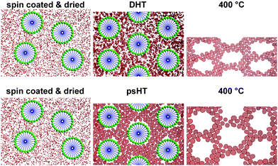 | ||
| Scheme 1 Directly after spin coating and drying at 60 °C (left) micelles are irregularly arranged and in between single precursor units are dispersed. Upon DHT the precursors condense to a loose network with partially very small crystallites but also many smaller precursor aggregates that are randomly arranged around the now ordered micelles (top middle). Upon calcination at 400 °C small nanocrystallites are formed and the whole film shrinks significantly perpendicular to the substrate (top right). In contrast during psHT at 100 °C the inorganic precursor condenses between the micelles arranging in a more ordered fashion. Small, uniformly sized crystalline nanoparticles are formed between the micelles stabilizing the structure (bottom middle). This process results in so much stability for the structure that upon template removal the crystalline particles slightly grow but only a small shrinkage of the pores normal to the surface can be observed (bottom right). The pores maintain their shape and are highly accessible for application. | ||
The thin films were prepared according to the following procedure:
The thin films were prepared on glass and silicon substrates of ca. 2 × 2 cm2. The cleaning included washing with an alkaline/soap solution, rinsing with distilled water and ultrasonic treatment in ethanol. Dust was removed directly before the final coating by spinning ethanol for a minute. 100 µl of each synthesis solution (for the exact compositions see ESI†) were spin-coated at 4000 rpm for half minute on the glass or silicon substrates at 10% relative humidity (RH). The low humidity was achieved by splitting dry nitrogen from a gas bottle in two paths. One was directed through a glass frit placed in distilled water. The final gas stream was pressed from the bottom into the spin coater and the humidity was adjusted by the gas flows of both streams. Every time after placing a substrate in the spin coater the coating was performed after a stable humidity value was reached. The fresh films were dried at 60 °C for one day; afterwards they were subjected to a water vapor atmosphere at 100 °C for four days at 90% RH. After the psHT, a thermal treatment at progressively higher temperature with a general increase (1 °C min−1) in temperature was employed.
In case of niobium oxide we were able to use either niobium(V) ethoxide or niobium(V) chloride as precursor. For the exact experimental conditions see ESI† (Methods). The as-synthesized thin film shows a peak in X-ray diffraction (XRD) measurements typical for mesostructured thin films with the employed template and inorganic material between the template micelles corresponding to Scheme 1. But as for most systems this structure is not stable for direct removal of the template neither by extraction nor calcination. Fig. 1A shows the X-ray diffraction pattern of the niobium oxide thin film after the psHT. During the psHT the mesostructure forms and solidifies as assumed in Fig. 1. The stabilization of the niobium oxide during the psHT then allows heating the sample with a ramp of 1 °C per minute up to 400 °C to remove the template. The small shift in the position of the first order peak in the XRD pattern in Fig. 1A depicts the extraordinary stability of this material after the psHT. No significant pore shrinkage is observed and Fig. 1B clearly exhibits a type IV isotherm of a mesoporous material with a porosity of up to 49% obtained in an ellipsometry porosimetry (EP) measurement.27,28 A thickness of 350 nm was derived from ellipsometric measurements for the thin film after psHT. Nitrogen sorption measurements on scratched of thin films revealed a BET surface area of 138 m2 g−1 and a mean pore sizes of 5.8 nm calculated by NLDFT. The thickness of the calcined thin film is reduced to about 290 nm, corresponding to 17% decrease, respectively. Fig. 1C shows the transmission electron microscopy (TEM) picture of a scratched piece of the thin film from the silicon substrate. It shows a layered pore arrangement at the phase boundary where the film is attached to the substrate and some disorder in the center. It is visible that the pores have kept an almost circular shape. This is in contrast to most literature reports where pores in thin films become strongly ellipsoidal15,29 upon template removal due to the distinct shrinkage of the thin film normal to the surface.
 | ||
| Fig. 1 Niobium oxide thin films: XRD pattern after psHT and after calcination at 400 °C (A); toluene physisorption measured by ellipsometry porosimetry on calcined thin film (B) and TEM micrograph (C) from the calcined porous thin film. | ||
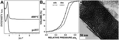
In case of titanium(IV) oxide the as-synthesized thin film shows the typical XRD pattern of a mesostructured material similar to the niobium oxide. Also this structure is not stable for the template removal without further treatments. The post-synthetic hydrothermal treatment of the unstructured thin film at the relatively low temperature of 100 °C leads to an almost complete crystallization of the titanium oxide around the mesophase. The XRD pattern of the titanium dioxide after the psHT and after calcination at 400 °C is depicted in Fig. 2A. Similar to the niobium oxide only a slight shift in the 2θ peak position is observed upon calcination proving the excellent crystallinity of the material before the calcination. Usually a strong shift for this step is reported in the literature.15,30,31 The Raman spectra (Fig. 2B) and the corresponding high resolution TEM (HRTEM) micrograph (Fig. 2C) of the sample after psHT show clearly the crystallinity of the titania (the corresponding wide angle XRD data are given in Fig. S1†). The crystallite sizes obtained by the Scherrer equation to the wide angle XRD data are 3.6 nm after the psHT and grow to 6.7 nm upon the heat treatment to 400 °C. The bands in the Raman spectra (Fig. 2B) correlate with the anatase modification of titania. The inset in Fig. 2C shows an electron diffraction pattern of a larger area as depicted in the corresponding HRTEM micrograph. The clearly visible rings are the 101, 004, 200, 211, 204, 215, and 224 corresponding to the anatase TiO2 structure (PDF no. 21-1272). XPS was carried out to investigate the surface compositions and chemical state of the calcined thin film (results are shown in Fig. S2†). The EP measurement depicted in Fig. 2D shows a typical type IV isotherm of a mesoporous material (comparable results were obtained for TiO2 powder scratched off from several thin films, Fig. S3(B)†). Evaluation of the EP measurements resulted in a surface area of about 150 m2 g−1, similar to the results obtained by the N2 physisorption measurements of the scratched off thin films of 138 m2 g−1. The pore size distribution revealed an apparent average pore diameter of about 8 nm, attributed to the shortest wall-to-wall distance in the distorted ellipsoidal mesopores. Pore size distributions (PSDs) have been calculated based on the desorption branch of the EP measurements of the isotherms (the corresponding PSD graphs for all discussed metal oxides are given in Fig. S4†). Comparable titania porosities from the synthesis with the special surfactant KLE were reported17 but were accompanied with a film shrinkage normal to the surface upon calcination of over 55% in comparison to less than 13% for our titania thin films. This reduced shrinkage and the optical transparency of our thin films (for transparency demonstration see Fig. S5†) is crucial for their application, e.g. in solar cell or as optical sensors.
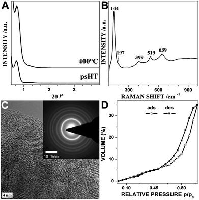 | ||
| Fig. 2 Titanium dioxide thin films: XRD pattern after psHT and after calcination at 400 °C (A); Raman spectra (B) and high resolution TEM micrograph (C) of the psHT treated thin film with anatase structure; the inset shows the anatase lattice planes in a selected area electron diffraction picture. (D) Ethanol ellipsometry porosimetry measurement of the thin film calcined at 400 °C. | ||
In contrast to the above discussed samples the synthesis of pure tin dioxide with F127 as structure director does not result in any mesostructure directly after spin coating. Just upon the post-synthetic hydrothermal treatment a structure is induced similar to the structure formation observed in the DHT process. On top of the structure formation at 100 °C a complete crystallization of the tin dioxide at this temperature can be observed. This crystallization leads to an excellent stability for high temperature treatment up to 600 °C which goes along with the crystallite growth without destroying the mesoporosity. Fig. 3A and B show the mesostructure formation and the temperature stability in the low angle region and the crystallization of the particles under psHT and the crystallite growth at 400 and 600 °C. Applying the Scherrer equation to the XRD data leads to particles sizes of 2.8 (psHT), 5.6 (400 °C), and 7.4 nm (600 °C) for the tin dioxide thin film. The isopropanol EP adsorption/desorption isotherm of the sample calcined at 400 °C depicted in Fig. 3C exhibits the typical type IV shape of a mesoporous material. It can be inferred that the excellent stability for the thermal removal of the structure director is based on the early crystallization of the tin dioxide in the post-synthetic hydrothermal treatment at 100 °C. The pore size distribution, obtained by applying the classical Kelvin equations for analysis of deformed spherical pores in combination with the desorption branch, reveals an average pore size of 7.8 nm (Fig. S4†). The corresponding nitrogen isotherm of the scratched off powders (Fig. S3(C)†) shows the typical type IV isotherm of cylindrical mesopores with sharp pore size distribution. The BET surface area for the scratched of material is 132 m2 g−1 and the pore size 7.3 nm is in good agreement with the results from the EP measurements. The HRTEM in Fig. 3D of the psHT thin film clearly shows the lattice fringes of the crystalline tin dioxide. It has cassiterite structure, the inset in Fig. 3D shows the corresponding lattice fringes. After the calcination the mesostructure is not only maintained but also the typical shrinkage of 30–50% normal to the surface of the thin films is reduced so significantly that the pores almost maintain their round shapes and order as can be easily seen in Fig. 3E. The HRTEM image in Fig. 3F illustrates the crystalline nature of the walls around the mesopores. The process of the crystallization around the mesopores around the micelles formed by the structure director is not restricted to the surfactant F127 or pure tin dioxide only. It can also be performed in the presence of dopants, e.g. Pd, Pt, and Cu (described elsewhere).
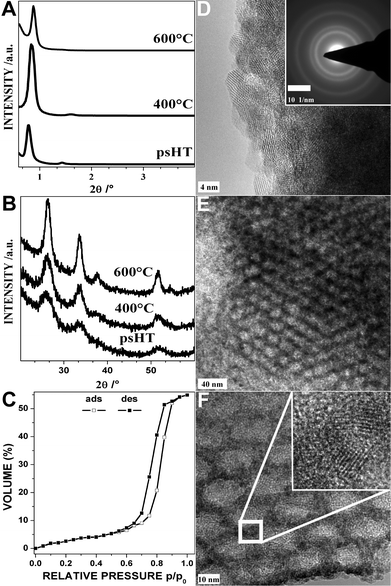 | ||
| Fig. 3 Tin dioxide thin films: XRD pattern after psHT, calcination at 400 °C and 600 °C (A and B). Isopropanol physisorption by ellipsometry porosimetry (C) of the thin film calcined at 400 °C. High resolution TEM micrograph of the psHT treated thin film before calcination (D) with an inset showing the corresponding selected area electron diffraction pattern. TEM micrographs with increasing resolution of the thin film calcined at 400 °C (E and F); the inset shows the lattice fringes of the nanocrystals forming the pore walls. | ||
In conclusion we show a new synthetic approach that overcomes the problems of the so far established methods. It allows the synthesis of metal oxide thin films with ordered nanopores at low temperatures. Furthermore, in the case of titania and tin dioxide crystalline pore walls can be achieved at unprecedented low temperatures of 100 °C allowing an easy thermal removal of the template by calcination without loss of mesostructure or significant shrinkage of the thin film normal to the substrate. This process will allow us to prepare new transparent thin film materials for semiconducting sensors and dye-sensitized solar cells and significantly enhance their desired properties.
Acknowledgements
We thank the University of Munich and especially Thomas Bein for his constant support. Special thanks to Jörg Schuster, Markus Döblinger, and Steffen Schmidt for their support on the TEM investigations. Shaofeng Shao thanks the Chinese Scholarship Council for financial support.Notes and references
- Y. F. Lu, R. Ganguli, C. A. Drewien, M. T. Anderson, C. J. Brinker, W. L. Gong, Y. X. Guo, H. Soyez, B. Dunn, M. H. Huang and J. I. Zink, Nature, 1997, 389, 364–368 CrossRef CAS.
- H. Yang, A. Kuperman, N. Coombs, S. MamicheAfara and G. A. Ozin, Nature, 1996, 379, 703–705 CrossRef CAS.
- C. J. Brinker, Y. F. Lu, A. Sellinger and H. Y. Fan, Adv. Mater., 1999, 11, 579–585 CrossRef CAS.
- N.-L. Wu, S.-Y. Wang and I. A. Rusakova, Science, 1999, 285, 1375–1377 CrossRef CAS.
- C. Sanchez, C. Boissiere, D. Grosso, C. Laberty and L. Nicole, Chem. Mater., 2008, 20, 682–737 CrossRef CAS.
- A. Schlossbauer, J. Kecht and T. Bein, Angew. Chem., Int. Ed., 2009, 48, 3092–12559 CrossRef CAS.
- R. Köhn and M. Fröba, Catal. Today, 2001, 68, 227–236 CrossRef CAS.
- C. T. Kresge, M. E. Leonowicz, W. J. Roth, J. C. Vartuli and J. S. Beck, Nature, 1992, 359, 710–712 CrossRef CAS.
- Q. S. Huo, D. I. Margolese, U. Ciesla, P. Y. Feng, T. E. Gier, P. Sieger, R. Leon, P. M. Petroff, F. Schuth and G. D. Stucky, Nature, 1994, 368, 317–321 CrossRef CAS.
- S. A. Bagshaw, E. Prouzet and T. J. Pinnavaia, Science, 1995, 269, 1242–1244 CrossRef.
- P. D. Yang, D. Y. Zhao, D. I. Margolese, B. F. Chmelka and G. D. Stucky, Nature, 1998, 396, 152–155 CrossRef CAS.
- D. Grosso, A. R. Balkenende, P. A. Albouy, M. Lavergne, L. Mazerolles and F. Babonneau, J. Mater. Chem., 2000, 10, 2085–2089 RSC.
- A. Gibaud, D. Grosso, B. Smarsly, A. Baptiste, J. F. Bardeau, F. Babonneau, D. A. Doshi, Z. Chen, C. J. Brinker and C. Sanchez, J. Phys. Chem. B, 2003, 107, 6114–6118 CrossRef CAS.
- N. Husing, B. Launay, D. Doshi and G. Kickelbick, Chem. Mater., 2002, 14, 2429–2432 CrossRef.
- E. L. Crepaldi, G. J. de Soler-Illia, D. Grosso, F. Cagnol, F. Ribot and C. Sanchez, J. Am. Chem. Soc., 2003, 125, 9770–9786 CrossRef CAS.
- D. Grosso, C. Boissiere, B. Smarsly, T. Brezesinski, N. Pinna, P. A. Albouy, H. Amenitsch, M. Antonietti and C. Sanchez, Nat. Mater., 2004, 3, 787–792 CrossRef CAS.
- B. Smarsly, D. Grosso, T. Brezesinski, N. Pinna, C. Boissiere, M. Antonietti and C. Sanchez, Chem. Mater., 2004, 16, 2948–2952 CrossRef CAS.
- T. Brezesinski, B. Smarsly, K.-I. Iimura, D. Grosso, C. Boissiere, H. Amenitsch, M. Antonietti and C. Sanchez, Small, 2005, 1, 889–898 CrossRef CAS.
- T. Brezesinski, A. Fischer, K.-I. Iimura, C. Sanchez, D. Grosso, M. Antonietti and B. M. Smarsly, Adv. Funct. Mater., 2006, 16, 1433–1440 CrossRef CAS.
- J. Lee, M. C. Orilall, S. C. Warren, M. Kamperman, F. J. DiSalvo and U. Wiesner, Nat. Mater., 2008, 7, 222–228 CrossRef CAS.
- T. Brezesinski, J. Wang, J. Polleux, B. Dunn and S. H. Tolbert, J. Am. Chem. Soc., 2009, 131, 1802–1809 CrossRef CAS.
- N. Urade Vikrant and W. Hillhouse Hugh, J. Phys. Chem. B, 2005, 109, 10538–10541 CrossRef CAS.
- J. H. Pan, S. Y. Chai, C. Lee, S.-E. Park and W. I. Lee, J. Phys. Chem. C, 2007, 111, 5582–5587 CrossRef CAS.
- J. Ba, J. Polleux, M. Antonietti and M. Niederberger, Adv. Mater., 2005, 17, 2509–2512 CrossRef CAS.
- A. Corma, P. Atienzar, H. Garcia and J.-Y. Chane-Ching, Nat. Mater., 2004, 3, 394–397 CrossRef CAS.
- A. S. Deshpande, N. Pinna, B. Smarsly, M. Antonietti and M. Niederberger, Small, 2005, 1, 313–316 CrossRef CAS.
- M. R. Baklanov, K. P. Mogilnikov, V. G. Polovinkin and F. N. Dultsev, J. Vac. Sci. Technol., B, 2000, 18, 1385–1391 CrossRef CAS.
- A. Bourgeois, A. B. Bruneau, S. Fisson, B. Demarets, D. Grosso, F. Cagnol, C. Sanchez and J. Rivory, Thin Solid Films, 2004, 447–448, 46–50 CrossRef CAS.
- X. Xu, B. Tian, J. Kong, S. Zhang, B. Liu and D. Zhao, Adv. Mater., 2003, 15, 1932–1936 CrossRef CAS.
- S. Y. Choi, B. Lee, D. B. Carew, M. Mamak, F. C. Peiris, S. Speakman, N. Chopra and G. A. Ozin, Adv. Funct. Mater., 2006, 16, 1731–1738 CrossRef CAS.
- D. Grosso, G. Soler-Illia, F. Babonneau, C. Sanchez, P. A. Albouy, A. Brunet-Bruneau and A. R. Balkenende, Adv. Mater., 2001, 13, 1085–1090 CrossRef CAS.
Footnote |
| † Electronic supplementary information (ESI) available: Methods—detailed description of applied synthesis and characterization methods, Fig. S1—XRD wide angle data for titania after psHT and calcination, Fig. S2—XPS spectra of mesoporous titania thin films, Fig. S3—nitrogen physisorption measurements of Nb2O5 (A), TiO2 (B), SnO2 (C) thin films scratched of wafers, Fig. S4—PSD from EP measurements of Nb2O5 (A), TiO2 (B), SnO2 (C) thin films, and Fig. S5—photo of glass slides with thin films of Nb2O5 (A), TiO2 (B), SnO2 (C), empty (D) for transparency comparison. See DOI: 10.1039/c0nr00079e |
| This journal is © The Royal Society of Chemistry 2010 |