Structured zeolitescatalysts with hierarchical channel structure†
Lijun
Gu
,
Ding
Ma
*,
Songdong
Yao
,
Chunlei
Wang
,
Wenjie
Shen
and
Xinhe
Bao
*
State Key Laboratory of Catalysis, Dalian Institute of Chemical Physics, Chinese Academy of Sciences, 116023, Dalian, China. E-mail: dma@dicp.ac.cn; xhbao@dicp.ac.cn; Fax: +86 411 8469 4447; Tel: +86 411 8437 9253
First published on 2nd February 2010
Abstract
Structured catalysts of mesoporous ZSM-5 matrixed over silicon carbide were successfully prepared and the obtained structured-zeolitic-catalyst has a multimodal porosity. This method also provided a means to immobilize catalytically active CNTs onto shape-tunable inorganic substrates.
Zeolitic materials are widely used in catalytic reactions and have industrial applications in oil refineries and petrochemical processes.1 In general, the zeolitic materials need to be properly shaped to meet the mechanical and mass transfer requirements of an industrial application. For reactions at relatively high temperatures of over 973 K, the way to shape the catalyst particles is an important consideration. The normal oxide binders such as α-Al2O3, ZrO2 or alumina–silica2 have the obvious defects of blocking catalytic active sites and hampering the diffusion of reactants/primary products in the zeolitic channels. Acidic binders can also cause severe carbonaceous deposition in high temperature reactions, which would result in rapid catalyst deactivation. The construction of structured zeolite/substrate catalysts is a current means to gain better control over the diffusion and hydrodynamics to give improved reaction performance. In addition to ceramics3 and metals4 that have been successfully matrixed for zeolites (via in situhydrothermal synthesis or pseudomorphic coating), silicon carbide, which has better chemical inertness, higher mechanical strength, and ease of shaping, is an attractive candidate for making structured zeolitic catalysts. Ivanova, Wine and Rebmann et al. have demonstrated that various types of zeolites can be grown in situ on silicon carbide. The resulting materials exhibited superior catalytic performances in important chemical reactions, such as the methanol-to-olefins process.5–7 This new generation of structured zeolitic catalyst gives innovative and exciting possibilities for applications in catalysis. Many works have also been performed in the construction of inorganic hierarchical structures, especially zeolites with multimodal porosity.8–12 Significantly, in a catalytic reaction, a hierarchically porous structure is vital in order for reactant molecules to have easy access to the active sites and products to diffuse away from the catalyst surface. Among the methods to fabricate zeolites with multimodal porosity, the hard template process has been shown to be the simplest and most efficient approach. Various organic moulds,9e.g., polystyrene spheres8 or one-dimensional nanomaterials (CNTs),12 have been reported to be effective hard templates, with which zeolitic structures containing a micropore/mesopore or micropore/macropore bimodal porosity were created.
In this work, a new approach to fabricate structured zeolitic catalysts with multimodal porosity is reported. Microporous ZSM-5 with a mesoporous structure has been made as a matrix on macroscopic SiC foam . This new catalyst material has a hierarchical pore system that can be very useful in catalytic reactions.
Scheme 1 gives a schematic diagram of the procedure to make structured ZSM-5 catalysts with hierarchical channel structure. The SiC supports (the SiC were prepared according to an improved method reported elsewhere.13 The SiC wafers were the commercial products of TanKeBlue Semiconductor Co. Ltd.) were first calcined at 1173 K for 4 h to give a nanoscopic layer of silica on its surface. Then, carbon nanotubes on SiC (CNTs@SiC) were prepared by a ferrocene-CVD method in an electrical furnace equipped with a quartz tube. SiC particles were dispersed on the quartz boat with a thickness of about 5 mm and the SiC wafer was placed directly on quartz boat. The furnace was heated up from room temperature to 973 K within 70 min at the N2 flow rate of 100 sccm. 10% H2 (N2 balanced, at 400 sccm) was switched into the reaction system when the temperature reached 973 K. Meanwhile, a ferrocene content of 0.02 g mL−1 in xylene was pumped into it with the flow rate of 0.1 mL min−1. After 40 min of reaction (5 min for SiC wafer), the temperature of the furnace was lowered to room temperature at the N2 flow rate of 100 sccm.
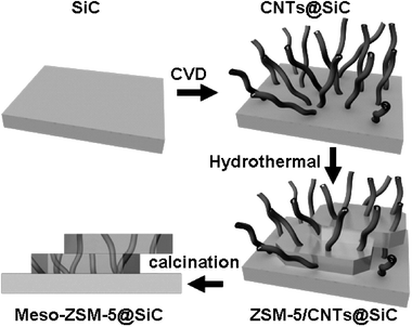 | ||
| Scheme 1 Carbon nanotube templated synthesis of novel structured catalysts of ZSM-5 on silicon carbide with hierarchical pore structure. | ||
After the CVD treatment, the color of the SiC support changed from dark grey for particles or green for wafer to black, which indicated that the surfaces of SiC were covered by CNTs. Scanning electron microscope (SEM) images showed that after the growth of CNTs on SiC (a SiC wafer in Fig. 1a, SiC particles in Fig. 1c), the morphology of the SiC support remained unchanged (Fig. S1† ). However, the entire surface was covered by a layer of CNTs with diameters between 20–60 nm. The length of the CNTs in the layer can be controlled by the CVD time. In this work, the length was around 20–30 μm on the SiC particles, and 5 μm on the SiC wafer.
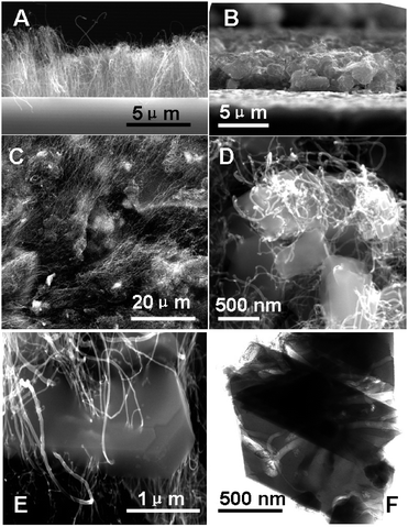 | ||
| Fig. 1 SEM images of (a) CNTs@SiC-wafer; (b) ZSM-5/CNTs@SiC-wafer; (c) CNTs@SiC; (d), (e) ZSM-5/CNTs@SiC and TEM image of (f) mesoporous zeolite crystals detached from the silica carbide support. | ||
An in situhydrothermal synthesis was employed to produce the CNTs in ZSM-5/SiC complex materials (ZSM-5/CNTs@SiC, if SiC wafer was used, then the product was denoted as ZSM-5/CNTs@SiC-wafer.). The molar ratios of the preparation solution were: TPAOH/TEOS/NaCl/NaAlO2/H2O 2.16![[thin space (1/6-em)]](https://www.rsc.org/images/entities/char_2009.gif) :5.62:3.43:0.22:1000. The mixture of 0.60 g NaCl, 54 mL H2O, 6.59 g TPAOH, 2.18 mL TEOS and 0.03 g NaAlO2 was stirred at 30 °C for 4 h. Then 60 mL mixture and 7 g CNT@SiC (or some CNTs@SiC-wafers) were put together into a Teflon-lined autoclave. Crystallization of ZSM-5 onto CNT@SiC was carried out at 443 K for 2 days. After crystallization, the solids were separated, washed with deionized water and dried at 393 K. The calcination was carried out at 823 K for 6 h to remove the template of TPAOH, and CNTs were eliminated by calcination at 973 K for 6 h. After the consecutive calcination, structured ZSM-5/SiC catalysts with mesopores (meso-ZSM-5@SiC and meso-ZSM-5@SiC-wafer) were successfully fabricated.
:5.62:3.43:0.22:1000. The mixture of 0.60 g NaCl, 54 mL H2O, 6.59 g TPAOH, 2.18 mL TEOS and 0.03 g NaAlO2 was stirred at 30 °C for 4 h. Then 60 mL mixture and 7 g CNT@SiC (or some CNTs@SiC-wafers) were put together into a Teflon-lined autoclave. Crystallization of ZSM-5 onto CNT@SiC was carried out at 443 K for 2 days. After crystallization, the solids were separated, washed with deionized water and dried at 393 K. The calcination was carried out at 823 K for 6 h to remove the template of TPAOH, and CNTs were eliminated by calcination at 973 K for 6 h. After the consecutive calcination, structured ZSM-5/SiC catalysts with mesopores (meso-ZSM-5@SiC and meso-ZSM-5@SiC-wafer) were successfully fabricated.
After the hydrothermal synthesis, it was interesting to see that ZSM-5 crystallites were grown on the surface of SiC despite the existing CNTs layer (Fig. 1b and d and Fig. S2† ). A close-up view by SEM (Fig. 1d) showed clearly that the zeolite crystals had CNTs inside them, i.e., they were actually penetrated by the CNTs. The directions of the pores inside the crystals were relatively random, except for some areas where the carbon nanotubes were aligned. The magnified image of single tubes of CNTs penetrating ZSM-5 on SiC is shown in Fig. 1e, which clearly reveals the complex structure of this material.
After the CNTs were totally removed, to leave ZSM-5 particles homogeneously deposited on the SiC substrate (Fig. S3† ), the existence of the zeolite on SiC was further confirmed by XRD characterization (Fig. 2a). These showed not only the characteristic reflections of silicon carbide, but also the signals of ZSM-5 on the meso-ZSM-5@SiC sample. This indicated that ZSM-5 crystals were coated onto the SiC particles, as seen in SEM images. The intense peak centered at ca. 21.8° of meso-ZSM-5@SiC and SiC was due to silica formed on the surface of SiC during the calcination at 1173 K before the synthesis. Fig. 1f shows a typical ZSM-5 crystal that had been peeled off from the SiC substrate. This showed that mesopores of size 20–60 nm were formed inside the crystal after the removal of the CNTs from the ZSM-5/CNTs@SiC complex by calcination. The weight percent of ZSM-5 zeolite of the final meso-ZSM-5@SiC was 11.7%. The adsorption–desorption isotherms of meso-ZSM-5@SiC and the free-standing ZSM-5 sample synthesized in the same condition (same hydrothermal bomb) are shown in Fig. 2b. The isotherm of free standing ZSM-5 shows a typical feature of microporous materials. However, the adsorption–desorption isotherm of meso-ZSM-5@SiC shows a sharp increase at P/P0 = 0 and a Type IV isotherm with a H3-type hysteresis loop. This confirmed the co-existence of microporosity and mesoporosity. All the evidence suggested that by our novel CVD-hydrothermal approach, structured ZSM-5 catalysts with a hierarchical channel system had been prepared. We need to point out that the mechanical stability of the zeolite layer on SiC substrate is quite good. Even under the very harsh condition of ultrasonic treatment for 1 h, the zeolite removed from the meso-ZSM-5/SiC composite was only 4.2 wt%. This method, once fully developed, can be extended to other zeolites to create mesoporous/microporous materials hosted on macroscopic SiC.
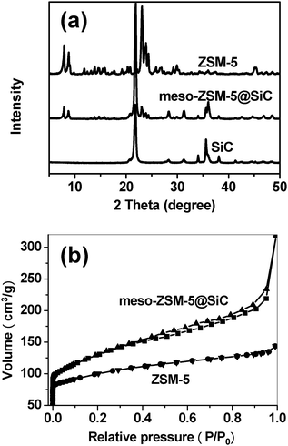 | ||
| Fig. 2 (a) XRD patterns of SiC, meso-ZSM-5@SiC and ZSM-5; (b) N2 adsorption and desorption isotherms of meso-ZSM-5@SiC and conventional ZSM-5 prepared in the same hydrothermal bomb. The isotherm of meso-ZSM-5@SiC has been normalized according to the loading of zeolite over SiC. SiC substrate has a BET surface area less than 1 m2 g−1. | ||
One needs to note, despite the rapid progress in CNT-based catalyst systems,14,15 that the question of how to shape the CNTs or metal-loaded-CNTs catalyst to suit an industrial application requirement is still an unsolved difficulty. One proposed solution was to grow CNTs on a substrate of silica spheres.16 As the interaction between the CNTs and the silica sphere was relatively weak, the CNTs could be easily peeled off the substrate and be unsuitable for practical applications. ZSM-5/CNTs@SiC materials, on the other hand, reinforced the anchoring of CNTs on the SiC surface through the zeolitic layer, and would provide an effective solution to this problem.
In summary, we have developed a novel approach to synthesize a structured zeolitic catalyst with multimodal porosity. Carbon nanotubes were grown on a silicon carbide support, which penetrated the zeolite ZSM-5 crystal layer subsequent formed by in situ hydrothermal crystallization. By removing the CNT template, mesoporous ZSM-5 supported on SiC was obtained. In addition, this method also provided a means (ZSM-5/CNTs@SiC) to immobilize catalytically active CNTs onto shape-tunable inorganic substrates. The immobilized CNTs by themselves, or after loading with catalytically active metal or metal oxide, can have potential applications in scaled-up catalytic reaction processes.
This research was supported by BAIREN project of CAS, Ministry of Science and Technology (China) “Project 973” (2005CB221405) and B.P. We thank Dr G. Hu (Exponent) for helpful discussion.
Notes and references
- A. Corma, Chem. Rev., 1997, 97, 2373 CrossRef CAS.
- X. Wu, A. Alkhawaldeh and R. G. Antony, Stud. Surf. Sci. Catal., 2002, 143, 217 CAS.
- M. Xu, M. Cheng and X. Bao, Chem. Commun., 2000, 1873 RSC.
- L. T. Y. Au, J. L. H. Chau, C. T. Ariso and K. L. Yeung, J. Membr. Sci., 2001, 183, 269 CrossRef CAS.
- S. Ivanova, B. Louis, M. J. Ledoux and C. Pham-Huu, J. Am. Chem. Soc., 2007, 129, 3383 CrossRef CAS.
- G. Wine, J. P. Tessonnier, C. Pham-Huu and M. J. Ledoux, Chem. Commun., 2002, 2418 RSC.
- G. Rebmann, V. Keller, M. J. Ledoux and N. Keller, Green Chem., 2008, 10, 207 RSC.
- B. T. Holland, C. F. Blanford and A. Stein, Science, 1998, 281, 538 CrossRef CAS.
- M. Choi, H. S. Cho, R. Srivastava, C. Venkatesan, D.-H. Choi and R. Ryoo, Nat. Mater., 2006, 5, 718 CrossRef CAS.
- Y. Tao, H. Kanoh, L. Abrams and K. Kaneko, Chem. Rev., 2006, 106, 896 CrossRef CAS.
- D. Trong On and S. Kaliaguine, Angew. Chem., Int. Ed., 2001, 40, 3248 CrossRef CAS.
- I. Schmidt, A. Boisen, E. Gustavsson, K. Ståhl, S. Pehrson, S. Dahl, A. Carlsson and C. J. H. Jacobsen, Chem. Mater., 2001, 13, 4416 CrossRef CAS.
- L. Gu, D. Ma, S. Yao, X. Liu, X. Han, W. Shen and X. Bao, Chem. Eur. J, 2009, 15, 13449 CAS.
- X. Pan, Z. Fan, W. Chen, Y. Ding, H. Luo and X. Bao, Nat. Mater., 2007, 6, 507 CrossRef CAS.
- J. Zhang, X. Liu, R. Blume, A. Zhang, R. Schlögl and D. Su, Science, 2008, 322, 73 CrossRef CAS.
- R. Xiang, G. Luo, Z. Yang, Q. Zhang, W. Qian and F. Wei, Nanotechnology, 2007, 18, 415703 CrossRef.
Footnote |
| † Electronic supplementary information (ESI) available: Details of sample preparation, characterization and catalytic reaction. See DOI: 10.1039/b922139e |
| This journal is © The Royal Society of Chemistry 2010 |