A novel high energy density rechargeable lithium/air battery†
Tao
Zhang
a,
Nobuyuki
Imanishi
*a,
Yuta
Shimonishi
a,
Atsushi
Hirano
a,
Yasuo
Takeda
a,
Osamu
Yamamoto
a and
Nigel
Sammes
b
aDepartment of Chemistry, Faculty of Engineering, Mie University, 1577 Kurimamachiya-cho, Tsu, Mie 514-8507, Japan. E-mail: imanishi@chem.mie-u.ac.jp; Fax: +81-59-231-9478; Tel: +81-59-231-9420
bDepartment of Metallurgical and Materials Engineering, Colorado School of Mines, 1500 Illinois Street, Golden, Colorado 80401, USA. E-mail: nsammes@mines.edu
First published on 5th February 2010
Abstract
A novel rechargeable lithium/air battery was fabricated, which consisted of a water-stable multilayer Li-metal anode, acetic acid–water electrolyte, and a fuel-cell analogous air-diffusion cathode and possessed a high energy density of 779 W h kg−1, twice that of the conventional graphite/LiCoO2 cell.
Lithium/air batteries are attractive energy storage systems in view of their high energy density for application in electric vehicles, the calculated energy density of which is comparable with that of gasoline. The first challenge for a rechargeable lithium/air battery is to ensure a reversible reaction. Such a battery, consisting of a thin Li metal foil anode and a carbon electrode with cobalt phthalocyanine as the catalyst, was initially reported to be recharged with good coulombic efficiency in 1996.1 More recently, Bruce et al.2 have presented high performance cells using a non-aqueous liquid electrolyte and a porous carbon electrode with electrolytic manganese dioxide as the catalyst. Although these systems are of considerable interest, their active life is limited by the diffusion of oxygen, carbon dioxide and water through the electrolyte and their subsequent reaction with lithium. To date, positive results have been obtained for these systems under pure oxygen or dry oxygen and nitrogen mixture.1–3 However, for practical application in electrical vehicles, the air used will contain moisture. The electrochemical performance of lithium/air batteries is drastically reduced when the cell is cycled in air, even when a hydrophobic membrane is used to prevent the infiltration of moisture from the air. Thus, protection of the Li metal anode from water is the most critical point for long term stability of the lithium/air battery as pointed out by Armand and Tarascon.4 Furthermore, previously reported lithium/air batteries have employed organic electrolytes and the discharge reaction product of Li2O2 or Li2O deposited on a carbon electrode. High charge–discharge polarization were observed in these cells and resulted in energy loss. Therefore, energy losses from charging and discharging should be reduced for applications such as electric vehicles.
Visco et al.5 have proposed a water-stable lithium electrode protected by NASICON-type water-stable solid electrolyte. However, we have observed that these solid electrolytes are unstable in strong basic and acidic media. The discharge/charge reaction of a lithium/air battery with an aqueous electrolyte solution is as follows:
| 2Li + 1/2O2 + H2O ↔ 2LiOH | (1) |
The LTAP was supplied by Ohara Inc., Japan. The thickness of the LTAP plate was ca. 150 μm. The electrical conductivity of the LTAP plate at 60 °C was ca. 4 × 10⁻⁴ S cm−1. The X-ray diffraction (XRD) features of the LATP plate are mainly due to the NASICON-type LiTi2(PO4)3 phase (Fig. 1A). The LTAP plate was stable in neutral water with lithium ions, but was unstable in 1 M aqueous LiOH (Fig. 1B) and produced a high resistance phase, evidenced by a peak at 23° 2θ, which was indexed to be the Li3PO4 phase. LTAP powder was completely decomposed in 5 M aqueous HCl solution after 1 week and showed a very different diffraction pattern (Fig. 1D). Thus, the stability of LTAP in a weak acid of acetic acid–water solution was examined. The XRD pattern of LTAP powder immersed in the LiOAc saturated 90 vol% HOAc aqueous solution for 3 weeks at 50 °C (Fig. 1C) showed no change from that of the pristine LTAP, which indicated structural stability. The electrical conductivity of sintered plate samples with Au sputtered electrodes was measured using the AC impedance technique. LTAP immersed in pure HOAc for 3 weeks showed a significant decrease in conductivity; however, this decrease was suppressed by the addition of LiOAc salt in the HOAc solution. No change in conductivity was observed for LTAP immersed in the LiOAc saturated 90 vol% HOAc aqueous solution (pH = 3.34) at 50 °C for 5 months. The amount of Li-ions in solution and the electrical conductivity in the LiOAc saturated HOAc–H2O solution increased with increasing H2O content. The content of Li-ions in the LiOAc-saturated 90 vol% HOAc aqueous solution was 228 g L−1 and the conductivity of the solution at room temperature was 2 × 10⁻³ S cm−1. The conductivity is slightly lower than that of an electrolyte for lithium-ion batteries, but is acceptable for practical applications.
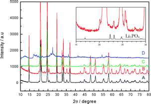 | ||
| Fig. 1 XRD patterns of (A) pristine LTAP, and (B)–(D) LTAP immersed in various aqueous solutions at 50 °C: (B) in aqueous 1 M LiOH for 3 weeks, (C) in 90 vol% HOAc–10 vol% H2O-saturated LiOAc for 3 weeks, (D) in aqueous 5 M HCl for one week. Powder XRD data was collected with a Rigaku RINT-2500HL diffractometer using Cu-Kα radiation and a step width of 0.03° 2θ. | ||
The lithium/air battery proposed in this study is constructed of a lithium-metal active layer, a lithium-ion conducting polymer buffer-layer, a water-stable LTAP protective layer, the HOAc–H2O–LiOAc electrolyte, and a carbon air cathode including superfine Pt particles (1–4 nm) as catalyst (Fig. 2) or a Pt-black only cathode (for Fig. 3). The Li/polymer electrolyte/LTAP anode was sealed using a plastic film, leaving a square window of 5 × 5 mm2. The polymer electrolyte was used to prevent reaction between the lithium anode and LTAP, because the water-stable LTAP is unstable in direct contact with lithium metal and produces a highly resistive layer at the interface.6 The polymer electrolyte used was polyethylene oxide (PEO) with Li(CF3SO2)2N (LiTFSI) (O/Li = 18/1). The method for preparation of the polymer electrolyte has been previously reported.6 The conductivity of the polymer electrolyte at 60 °C was ca. 3 × 10⁻⁴ S cm−1.
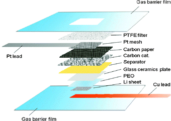 | ||
| Fig. 2 Schematic diagram of the proposed lithium–air system. | ||
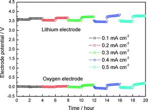 | ||
| Fig. 3 Time dependence of Li electrode and oxygen electrode potential change of LiPEO18LiTFSI|LTAP|HOAc (90 vol%)–H2O–LiOAc (sat) (10 vol%)|Pt-black air cell at various constant current densities at 60 °C. | ||
The cell resistance of the Li|PEO18LiTFSI|LTAP|HOAc–H2O–LiOAc (sat)|Pt-black air cell was 5466 Ω cm2 at 25 °C and drastically decreased to 185 Ω cm2 at 60 °C (see Fig. S1 in ESI†). The cell resistance is comparable to that of a cell with aqueous 1 M LiCl solution.7 According to the impedance analysis, the cell resistance is mainly due to the interface resistance between the lithium anode and polymer electrolyte and also between the polymer electrolyte and LTAP. The resistance between LTAP and the electrolyte solution was low. The open circuit voltage (OCV) of this cell was 3.69 V at room temperature, and this value remained constant for one month. The OCV is almost the same as that of the Li|PEO|LTAP|aqueous 1 M LiCl|Pt-black air cell (3.70 V).6 The following reversible cell reactions for the anode, cathode and total cell can be respectively expressed as:
| 2Li ↔ 2Li+ + 2e, | (2) |
| 1/2O2 + 2CH3COOH + 2e ↔ H2O + 2CH3COO−, | (3) |
| 2Li + 1/2O2 + 2CH3COOH ↔ 2CH3COOLi + H2O. | (4) |
The time dependence of the Li electrode potential and the oxygen electrode potential of the Li/PEO18LiTFSI|LTAP|HOAc–H2O–LiOAc (sat)|Pt-black air cell measured at various constant current drains at 60 °C and under open air are shown in the Fig. 3. The polarization at the lithium electrode and oxygen electrode is very low at a current density as high as 0.5 mA cm−2 during the charge and discharge processes. Low electrode polarization is important to obtain high energy conversion efficiency for the rechargeable battery. Lithium/air cells with the organic electrolyte have high polarization during the charge/discharge process.2 The high polarization may be due to the high activation energy required to reduce the Li2O2 reaction product during charge and to produce Li2O2 during discharge. Recently, an excellent air electrode catalyst was proposed by Bruce et al.,2 although the polarization was still high. The charge process in our system is the oxidation of H2O, as shown in eqn (3), which has been extensively studied in water electrolysis to be not so high at a current density of several mA cm−2. The oxygen overpotential in 28% KOH solution at 70 °C was as low as 260 mV at 75 mA cm−2 on NiCo2O4.8 The oxygen reduction reaction on a carbon electrode with a Pt-black catalyst in aqueous solution has been well known for fuel cells; the overpotential in 85% H3PO4 solution at 120 °C was only 200 mV at 10 mA cm−2.9
The results shown in Fig. 3 were obtained for the test cell with an excess amount of the cathode active materials of HOAc. According to the cell reaction of Li/HOAc/air, the cell capacity depends on the amount of HOAc. In order to estimate the energy density of the proposed Li/HOAc/air system, it is important to investigate what amount of the active HOAc materials can be used. Cells with a defined amount of the LiOAc saturated HOAc (90 vol%) aqueous solution and an excess amount of lithium anode were constructed, where the HOAc solution was infiltrated in a porous polyethylene separator (100 μm thick), and a carbon sheet (320 μm thick) air electrode with a platinum catalyst was used as the air electrode (Fig. 2). The charge–discharge performance was examined at 0.5 mA cm−2 and 60 °C under 3 atm of air (Fig. 4(a)). Flat discharge and charge potentials were obtained. A discharge capacity of 225 mA h g−1 was obtained for 56% HOAc utilization. The estimated energy density from the weight of the lithium anode and HOAc is as high as 779 W h kg−1. This energy density should be compared to that estimated from the electrode capacities and discharge cell voltage for a typical lithium-ion battery with a LiCoO2 cathode and graphite anode (380 W h kg−1),10 and also that estimated for a lithium-air battery with gel-polymer electrolytes (250–350 W h kg−1) reported by Abraham et al.1 The present result is two times higher than that of the graphite/LiCoO2 cell. Therefore, the proposed lithium-air batteries are expected to have an energy density of more than 400 W h kg−1 in practical applications, considering the practical energy density established for graphite/LiCoO2 batteries is 200 W h kg−1. The prototype lithium/air cell can retain a discharge–charge capacity of 250 mA h g−1 (based on the weight of HOAc) within 15 cycles, as shown in Fig. 4(b). In this case, the HOAc utilization was the same as that in Fig. 4(a) and the cut-off voltage was set as 3.2 V. The potential difference between the discharge and charge platform in the second cycle was 0.75 V, which suggests low overpotential characteristics for the aqueous lithium/air battery.
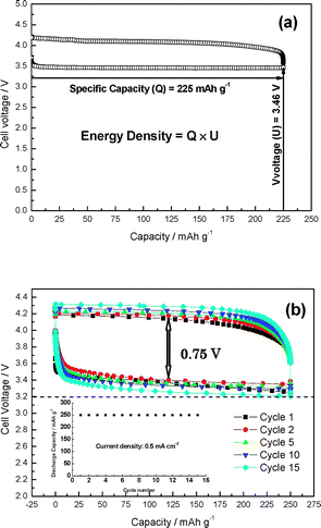 | ||
| Fig. 4 Charge–discharge performance of Li|PEO|LTAP|HOAc–H2O–LiOAc (sat)|carbon air cell at 0.5 mA cm−2 and 60 °C. (a) The volume ratio of the electrolyte was 90/10 HOAc/H2O. (b) The amount of HOAc in the electrolyte was defined as 1 mg. The cell was sealed in a high pressure vessel with 3 atm of air to suppress evaporation of the electrolyte. | ||
In summary, we have proposed a new type of rechargeable lithium-air battery with an expected energy density of more than 400 W h kg−1. Optimization of the cell construction will be continued to improve the cycling performance. We are presently attempting to develop a battery with lower interface resistance between the lithium metal and PEO buffer-layer, an appropriate cathode structure with a good balance of hydrophobic and hydrophilic properties, and a new catalyst for the air electrode to obtain lower polarization.
This work was supported by the New Energy and Industrial Technology Development Organization (NEDO) of Japan under the project “Development of High Performance Battery System for Next-Generation Vehicles”. We thank Ohara Inc. for supplying the LTAP samples.
Notes and references
- (a) K. M. Abraham and Z. Jiang, J. Electrochem. Soc., 1996, 143, 1 CrossRef CAS; (b) M. R. Palacín, Chem. Soc. Rev., 2009, 38, 2565 RSC.
- (a) T. Ogasawara, A. Débart, M. Holzapfel, P. Novak and P. G. Bruce, J. Am. Chem. Soc., 2006, 128, 1390 CrossRef CAS; (b) A. Débart, A. J. Paterson, J. Bao and P. G. Bruce, Angew. Chem., Int. Ed., 2008, 47, 4521 CrossRef CAS.
- (a) J. Read, K. Mutolo, M. Ervin, W. Behl, J. Wolfenstine, A. Driedger and D. Foster, J. Electrochem. Soc., 2003, 150, A1351 CrossRef CAS; (b) S. S. Sandhu, J. P. Fellner and G. W. Brutchen, J. Power Sources, 2007, 164, 365 CrossRef CAS.
- M. Armand and J.-M. Tarascon, Nature, 2008, 451, 652 CrossRef CAS.
- S. J. Visco, E. Nimon, B. Katz, L. C. D. Jonghe and M. Y. Chu, Abstract 0389, The 210th Electrochemical Society Meeting Abstracts, Cancun, Mexico, 2006, Vol. 2006-2 Search PubMed.
- T. Zhang, N. Imanishi, S. Hasegawa, A. Hirano, J. Xie, Y. Takeda, O. Yamamoto and N. Sammes, J. Electrochem. Soc., 2008, 155, A965 CrossRef CAS.
- T. Zhang, N. Imanishi, S. Hasegawa, A. Hirano, J. Xie, Y. Takeda, O. Yamamoto and N. Sammes, Electrochem. Solid-State Lett., 2009, 12, A132 CrossRef CAS.
- R. L. LeRoy, M. B. Jonjua, R. Renaud and U. Leuenberger, J. Electrochem. Soc., 1979, 126, 1674 CrossRef CAS.
- W. Vogel, J. Lundquist and A. Bradford, Electrochim. Acta, 1972, 17, 1735 CrossRef CAS.
- (a) K. Mizushima, P. C. Jones, P. J. Wiseman and J. B. Goodenough, Solid State Ionics, 1981, 3–4, 171 CrossRef CAS; (b) Z. Jiang, M. Alamgir and K. M. Abraham, J. Electrochem. Soc., 1995, 142, 333 CrossRef CAS.
Footnote |
| † Electronic supplementary information (ESI) available: Fig. S1: Arrhenius plots and impedance spectra of the cell used for Fig. 3. See DOI: 10.1039/b920012f |
| This journal is © The Royal Society of Chemistry 2010 |