Logic circuits constructed with an ion-sensitive fluorescent molecule 1,2-di[5-methoxy-2-(2-pyridyl)thiazoyl]ethyne†
Chun-Hu
Xu
,
Wei
Sun
,
Yao-Rong
Zheng
,
Chen-Jie
Fang
,
Can
Zhou
,
Jing-Yi
Jin
and
Chun-Hua
Yan
*
Beijing National Laboratory for Molecular Sciences, State Key Lab of Rare Earth Materials Chemistry and Applications & PKU-HKU Joint Lab in Rare Earth Materials and Bioinorganic Chemistry, Peking University, Beijing, 100871, China. E-mail: yan@pku.edu.cn; Fax: +86-10-62754179; Tel: +86-10-62754179
First published on 3rd February 2009
Abstract
The fluorescence behaviours of a chemical-sensitive fluorescent molecule 1,2-di[5-methoxy-2-(2-pyridiyl)thiazoyl]ethyne (DMPTE) at different protonation and coordination states were studied. Upon addition of protons, metal ions and other chemicals, the fluorescent states can be switched reversibly. On the basis of the changes of fluorescence output signals from particular wavelengths in response to different combination sets of two particular external stimuli, the entire set of 2-bit Boolean binary logic functions were realized at the molecular level, including PASS 0, PASS 1, YES, NOT, OR, NOR, INHIBIT, IMPLICATION, AND, NAND, XOR, XNOR, and different logic functions were integrated reconfigurably within DMPTE. Besides, starting from the same initial state, a series of three-input logic gates and circuits were also constructed. Furthermore, the stepwise recognition process of DMPTE to different chemical input signals can also be utilized to distinguish different input sequences, thus a molecular keypad lock that authenticates three-digit password entries is indicated.
Introduction
The realization of Boolean logics at the molecular level is attracting great interest in recent years.1 Molecular or supramolecular systems, which can undergo various configuration movements or spectral changes in response to external stimuli, such as chemionics,2 temperature,3redox potential,4 and irradiation,5 have been implemented as processing units for many different Boolean logic functions. Compared to the conventional silicon-based electronic logic gates, molecular logic systems provide a feasible strategy not only for mimicking the logic devices down to the nano-scale, but for highly functional integration within a single processing unit.1a,b,6 Especially the different changes either in different types of spectra or at different wavelengths in the same spectrum triggered by the same input signals lay a foundation for reconfiguration of the logic functions in a single molecule.1f,g,7 A few combinatorial logic gates, which show response to more than two inputs, have also been accomplished at the molecular level.8 These results demonstrate a facile and feasible strategy for realizing complex logic functions. Nowadays, the research interest in molecular logics has been extended to the realization of logic devices, such as molecular calculators and password-authentication devices.9–12To realize logic functions at the molecular level, several models of molecules have been presented.1c,2e–g,7c,8c,9a,f De Silva has reported a strategy for preparing multi-input-sensitive molecules with spectral output signals,13 which contain multiple receptors for recognition with the chemical inputs. The output signals can be encoded as absorption or photoluminescence, depending on the choices of chromophores. The fluorescence intensity at special wavelengths, and the sum, difference or ratio of the intensities at different wavelengths could all be employed as the output signals.1g The output signals solely in fluorescence provide a high resolution down to the molecular level, and afford ease for monitoring on the surface.14 Up to now, however, functional molecules that can carry out multiple 2-bit Boolean logics from the same initial state solely with fluorescence output mode has rarely been reported.15 Thus design and synthesis of simple molecules that are capable of performing multiple logic operations is still a challenge in the field of construction of molecular devices and machines.
Recently, we have prepared a new organic fluorophore 1,2-di[5-methoxy-2-(2-pyridiyl)thiazoyl]ethyne (DMPTE) (Chart 1), which exhibits a chemical-sensitive fluorescent behavior.11g Under different protonation and coordination states, DMPTE undergoes an ON–OFF fluorescence switching process. The low and high fluorescence intensities are encoded with 0 and 1 in binary algebra, and the fluorescence changes can be described by a series of Boolean logic gates. Starting from a dichloromethane solution of neutral DMPTE, the entire set of 2-bit Boolean logic gates (PASS 0, PASS 1, YES, NOT, OR, NOR, INHIBIT, IMPLICATION, AND, NAND, XOR, XNOR) have been constructed at the molecular level. Different 2-bit Boolean logic gates are further reconfigured simply by delicate choices of combinations of input signals and fluorescent output signals at different emission wavelengths, and a comparator is obtained at the molecular level in the meanwhile. The neutral DMPTE can also be applied to perform three-input logics, including EnNOR logic gate, enabled IMPLICATION logic gate and three-input molecular logic circuits. The fluorescent changes of DMPTE are also dependent on the sequence of several input signals, which implements a molecular keypad lock, suggesting the potential of DMPTE applied in the field of information security.
 | ||
| Chart 1 Structure of DMPTE. | ||
Experimental
All the solvents and metal salts were purchased from commercial sources and used without further purification. The spectral characterizations were carried out in dichloromethane (HPLC grade) solution at 25 °C in a 10 mm quartz cell. The concentration of DMPTE was 2 × 10⁻⁵ mol L−1. The fluorescence emission spectra were recorded upon the excitation at 350 nm on a Hitachi F-4500 fluorescence spectrometer. The quantum yields were measured with the method used before (ESI†).11gResults and discussion
Fluorescence properties of DMPTE
In dichloromethane solution, neutral DMPTE exhibits an emission band centered at 450 nm upon excitation at 350 nm, while the diprotonated state H2DMPTE formed with the introduction of trifluoroacetic acid (TFA) shows a strong fluorescence emission band centered at 535 nm (Fig. 1). When DMPTE is protonated, the electron-withdrawing ability of the pyridyl ring is increased, lowering the energy gap between the frontier molecular orbitals, so both the absorption and emission spectra display distinct bathochromic shifts. Addition of triethylamine (TEA) to the acidic solution neutralizes the TFA and restores the emission band at 450 nm, while only addition of TEA almost brings about no changes to the fluorescence behaviour of DMPTE (Fig. 1). The fluorescence properties of DMPTE with simultaneous addition of TFA and TEA are dependent on their relative amounts. The fluorescence quantum yields for neutral DMPTE and protonated DMPTE in presence of three equivalents of TFA in dichloromethane are 0.15 and 0.45, respectively. | ||
| Fig. 1 Fluorescence spectrum (λex = 350 nm) of DMPTE (0.02 mmol L−1 in dichloromethane) in the presence of different chemical introductions: (a) no chemical, (b) 0.11 mol L−1 triethylamine, (c) 0.20 mol L−1 trifluoroacetic acid, (d) 0.06 mmol L−1 (NH4)2Ce(NO3)6, (e) 0.06 mmol L−1CuCl2. | ||
Since there is both a pyridine ring and a thiazole ring within either MPT moiety of DMPTE, it is also inclined to bind with metal ions. The introduction of paramagnetic metal ions may afford a barely fluorescent complex, due to the enhanced efficiency of non-irradiative deactivation. Among all the used divalent metal ions, DMPTE exhibits a selective response to Cu2+, producing a 2 : 1 complex.11g Upon addition of cupric ion, the emission at 450 nm is gradually quenched due to the coordination interaction between copper and DMPTE (Fig. 1). From the fluorescence titration experiment, the binding constant between DMPTE and Cu2+ is 7 × 10¹¹ mol−2 L2 (Fig. S1 in ESI†).16 In the meanwhile, formation of the Cu2DMPTE complex is prohibited by the addition of competing ligands, such as tetraethylammonium bromide (TEAB) and TEA, that can also bind strongly with cupric ion. With the introduction of TEAB to the nonfluorescent Cu2DMPTE solution or simultaneous addition of TEAB and Cu2+ to the neutral DMPTE solution, the competing ligand bromide anion liberates DMPTE from Cu2DMPTE, resulting in a recovery of the fluorescence at 450 nm. Introduction of TEA to the nonfluorescent Cu2DMPTE solution can also lead to the similar results.
Besides, the responses of Cu2DMPTE to protonic solution are different from that of free DMPTE solution. Only excessive TFA increases the emission band at 535 nm. Also, in the presence of enough protons in solution, the coordination between cupric ion and TEAB is unaffected, while that between cupric ion and TEA is blocked, affording different spectral changes.
In addition, the fluorescence behaviour of DMPTE can also be modified by addition of oxidative metal ions, such as Ce4+. Addition of ceric(IV) ion quenches the fluorescence of DMPTE, similar to that of cupric ion, due to the formation of a nonfluorescent complex (Fig. 1). The stoichiometry of cerium(IV) to DMPTE is also determined to be 2 : 1, and the binding constant is 1 × 10¹¹ mol−2 L2 as determined from the fluorescence titration experiment (Fig. S2 in ESI†). Besides the coordination effect, the oxidation capacity of Ce4+ also plays a significant role in fluorescence quenching, because addition of non-oxidative Ce3+ does not quench the fluorescence of DMPTE (Fig. S3 in ESI†). Introduction of other oxidants, such as NOBF4, increases the fluorescence intensity, demonstrating that the coordination capacity of Ce4+ is very important for the fluorescence quenching (Fig. S4 in ESI†).
In the presence of protons, addition of Ce4+ brings little influence to the emission band at 450 nm, while simultaneous addition of Ce3+ and protons red shifts the fluorescence emission to about 535 nm, similar to the case with only protons introduced. The difference between Ce4+ and Ce3+ relies on their different oxidation capabilities. After oxidation, the DMPTE molecule is also positively charged, so its coordination capacity with the metal ion is decreased. Besides, the presence of protons hamper the coordination interactions between oxidative DMPTE species and ceric ion. The fluorescence emission is thus maintained with protons and Ce4+ added simultaneously.
Strategy for constructing logic gates with DMPTE
As described above, there exist more reception sites within the DMPTE molecule than the parent compound MPT,17 so DMPTE can exhibit more coordination modes towards protons and metal ions (Chart 2) and it displays various fluorescence changes in response to introduction of different chemicals.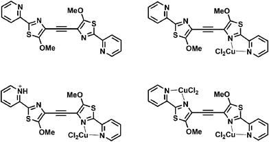 | ||
| Chart 2 Different coordination modes of DMPTE. | ||
To encode the Boolean logics in the present molecule, the versatile fluorescence behaviour of DMPTE in response to introduction of different chemicals are analyzed in binary logic.
The reversible protonation processes of DMPTE produce non-synchronous changes at two different fluorescent wavelengths, which can be utilized as two parallel output channels for the fabrication of molecular logics. Also, the sum, difference or ratio of the fluorescence intensities at these two emission wavelengths can also be employed as an output signal. The same input set triggers different fluorescent changes at various wavelengths, and then produces reconfigurable molecular logic gates. The emission bands of the two states overlap only to a small extent, indicating that a high ON–OFF signal contrast can be recorded during the conversion between different states. The fluorescence can also be switched between ON and OFF by addition of paramagnetic or oxidative metal ions (Cu2+ and Ce4+), which provides an additional switch in the channel at 450 nm. Thus, in response to protons and metal ions, DMPTE behaves as a dual-sensitive fluorescent switch. Furthermore, the binding between protons/metal ions and DPMTE and the responding fluorescence switch can be altered by addition of base or competing ligands, respectively. In summary, DMPTE can exhibit different spectral responses to multiple chemical-encoded input signals. The interactions on DMPTE among protons, metal ions and competing ligands, either in cooperation or in prohibition, trigger different fluorescent changes. Therefore, the fluorescent switches in response to chemical inputs are capable of executing multiple binary Boolean logics at the molecular level.
If the several chemical inputs are introduced in different combination sets, the fluorescence properties of the current system show a variety of different states. The distinct fluorescence properties of varied states of DMPTE enable the integration of multiple logic gates in a single molecule. Besides some parallel mutually complementary logic gates, such as PASS 0/PASS 1, INHIBIT/IMPLICATION, YES/NOT and OR/NOR, some three-function logic gates are also integrated within the neutral DMPTE solution as their same initial state reconfigurably. In addition, it is probable to construct some three-input logic circuits.
Two-input logic gates
 | ||
| Fig. 2 Molecular logic gates OR and NOR. (Top) Fluorescent changes (λex = 350 nm) for DMPTE (0.02 mmol L−1) in dichloromethane. (Bottom) The truth table for the logic gates. Inputs: 0.1 mol L−1TFA. Outputs: fluorescence intensity at 450 nm (O1), 535 nm (O2), respectively. | ||
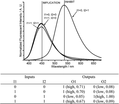 | ||
| Fig. 3 Molecular logic gates IMPLICATION and INHIBIT. (Top) Fluorescent changes (λex = 350 nm) for DMPTE (0.02 mmol L−1) in dichloromethane. (Bottom) The truth table for the logic gates. Inputs: 0.11 mol L−1TEA (I1), 0.12 mol L−1TFA (I2). Outputs: fluorescent intensity at 450 nm (O1), 535 nm (O2), respectively. | ||
If the amount of acid (I1) is in large excess to that of base (I2), it produces different logic gates. The addition of base (I1 = 1, I2 = 0) or acid (I1 = 0, I2 = 1) produces strong fluorescent intensities at 450 nm (O1 = 1, O2 = 0) or 535 nm (O1 = 0, O2 = 1), respectively. If acid and base are introduced together (I1 = I2 = 1), the remaining acid, after the neutralization reaction, still produces a protonated DMPTE, exhibiting a strong fluorescence at 535 nm (O2 = 1). The fluorescent changes at 450 nm (O1) produce a NOT logic gate, while the fluorescent changes at 535 nm (O2) fabricates a YES logic gate (Fig. 4 and Fig. S7 in ESI†).
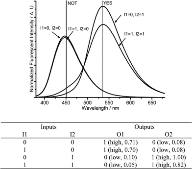 | ||
| Fig. 4 Molecular logic gates NOT and YES. (Top) Fluorescent changes (λex = 350 nm) for DMPTE (0.02 mmol L−1) in dichloromethane. (Bottom) The truth table for the logic gates. Inputs: 0.03 mol L−1TEA (I1), 0.12 mol L−1TFA (I2). Outputs: fluorescence intensity at 450 nm (O1), 535 nm (O2), respectively. | ||
 | ||
| Fig. 5 Molecular logic gates PASS 1 and PASS 0. (Top) Fluorescent changes (λex = 350 nm) for DMPTE (0.02 mmol L−1) in dichloromethane. (Bottom) The truth table for the logic gates. Inputs: 0.11 mol L−1TEA (I1, I2). Outputs: fluorescence intensity at 450 nm (O1), 535 nm (O2), respectively. | ||
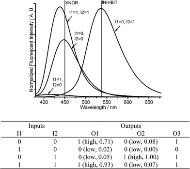 | ||
| Fig. 6 Molecular logic gates XNOR and INHIBIT. (Top) Fluorescent changes (λex = 350 nm) for DMPTE (0.02 mmol L−1) in dichloromethane. (Bottom) The truth table for the logic gates. Inputs: 0.06 mmol L−1 (NH4)2Ce(NO3)6 (I1), 0.12 mol L−1TFA (I2). Outputs: fluorescence intensity at 450 nm (O1), 535 nm (O2) and the sum of fluorescence intensities at both 450 and 535 nm (O3), respectively. | ||
Since the XNOR gate functions as an inverted XOR gate, which gives the opposite outputs in response to the same inputs, a XOR gate can be constructed through the negative logic setting.10b The low and high fluorescent states are denoted as logic 1 and 0 states, respectively, and then the XOR logic gate is constructed by the fluorescent changes at 450 nm in response to Ce4+ and protons.
Starting with the neutral DMPTE solution, with the same input set as that in the construction of XNOR gate, an INHIBIT logic gate is constructed when the output signal is recorded at 535 nm (Fig. 6 and Fig. S8 in ESI†). The introduction of Ce4+ (I1 = 1, I2 = 0) quenches the fluorescence both at 450 and 535 nm (O1 = 0, O2 = 0), while the introduction of protons (I1 = 0, I2 = 1) quenches the emission at 450 nm and enhances the fluorescence emission at 535 nm (O1 = 0, O2 = 1). When both inputs are present (I1 = 1, I2 = 1), only the fluorescence intensity at 450 nm is high (O1 = 1, O2 = 0).
An XNOR gate and an INHIBIT logic gate are constructed synchronously. From the viewpoint of binary algebra, the chemical processes are interpreted as follows: when the two inputs are equal (I1 = 0, I2 = 0 or I1 = 1, I2 = 1), the combinatorial logic produces the same output signal (O1 = 1, O2 = 0). When the two inputs are unequal, either I1 > I2 or I1 < I2 (I1 = 1, I2 = 0 or I1 = 0, I2 = 1), the combinatorial logic produces different outputs (O1 = 0, O2 = 0 for I1 = 1, I2 = 0, and O1 = 0, O2 = 1 for I1 = 0, I2 = 1, respectively). Thus judged by the different fluorescent states, the relative value of the two inputs can be determined. That is to say, a magnitude comparator is constructed, which can judge the comparative magnitude of two input signals.
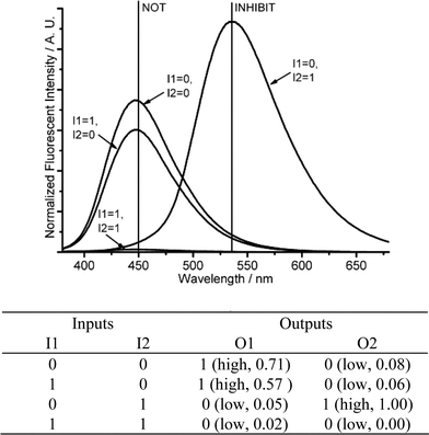 | ||
| Fig. 7 Molecular logic gates NOT-INHIBIT-NAND. (Top) Fluorescence changes (λex = 350 nm) for DMPTE (0.02 mmol L−1) in dichloromethane. (Bottom) The truth table for the logic gates. Inputs: 0.06 mmol L−1CuCl2 and 0.11 mol L−1TEA (I1), 0.12 mol L−1TFA (I2). Outputs: fluorescence intensity at 450 nm (O1), 535 nm (O2), respectively. | ||
 | ||
| Fig. 8 Molecular logic gates NOT-AND-IMPLICATION. (Top) Fluorescence changes (λex = 350 nm) for DMPTE (0.02 mmol L−1) in dichloromethane. (Bottom) The truth table for the logic gates. Inputs: 0.06 mmol L−1CuCl2 and 0.12 mol L−1TFA (I1), 0.12 mmol L−1TEAB (I2). Outputs: fluorescence intensity at 450 nm (O1), 535 nm (O2) and the sum of fluorescence intensities at both 450 and 535 nm (O3), respectively. | ||
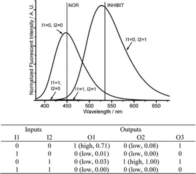 | ||
| Fig. 9 Molecular logic gates NOR-INHIBIT-NOT. (Top) Fluorescence changes (λex = 350 nm) for DMPTE (0.02 mmol L−1) in dichloromethane. (Bottom) The truth table for the logic gates. Inputs: 0.06 mmol L−1CuCl2 (I1), 0.12 mol L−1TFA (I2). Outputs: fluorescence intensity at 450 nm (O1), 535 nm (O2) and the sum of fluorescence intensities at both 450 and 535 nm (O3), respectively. | ||
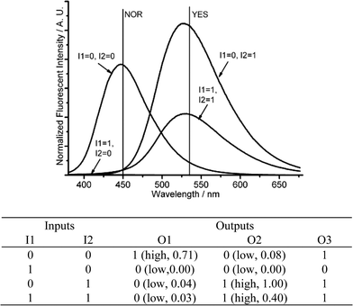 | ||
| Fig. 10 Molecular logic gates NOR-YES-IMPLICATION. (Top) Fluorescent changes (λex = 350 nm) for DMPTE (0.02 mmol L−1) in dichloromethane. (Bottom) The truth table for the logic gates. Inputs: 0.06 mmol L−1CuCl2 (I1), 0.12 mol L−1TFA and 0.12 mmol L−1TEAB (I2). Outputs: fluorescence intensity at 450 nm (O1), 535 nm (O2) and the sum of fluorescence intensities at both 450 and 535 nm (O3), respectively. | ||
Three-input combinatorial logics
The current molecule DMPTE can also be applied to construct logic circuits with three-input signals and multiple fluorescent output signals. Starting from the neutral DMPTE solution, where protons are absent (I3 = 0), the introduction of cupric ion (I1) and bromide (I2) realizes an IMPLICATION logic gate (O1) and a PASS 0 logic gate (O2) at 450 and 535 nm, respectively.When protons are introduced (I3 = 1), the logic expressions corresponding to the introduction of cupric ion (I1) and bromide (I2) are changed (Fig. 11 and Fig. S13 in ESI). When only protons are introduced (I1 = I2 = 0, I3 = 1), the fluorescence emission can only be detected at 535 nm (O1 = 0, O2 = 1). When cupric ion and protons are introduced (I1 = I3 = 1, I2 = 0), the fluorescence can not be detected at either 450 or 535 nm (O1 = O2 = 0). When bromide and protons are both introduced (I1 = 0, I2 = I3 = 1), the fluorescence is only distinct at 535 nm (O1 = 0, O2 = 1). The presence of three inputs decreases the emission at 450 nm remarkably, but promotes the fluorescence at 535 nm (O1 = 0, O2 = 1). An enabled IMPLICATION function is constructed at the 535 nm (O2). Notably, both the outputs (O1 and O2) are in fluorescent mode, and share the same logic 0 and logic 1 setting, thus a new output signal (O3) is recorded with the sum of two outputs at 450 and 535 nm. The introduction of the three inputs produces a three-output logic circuit.
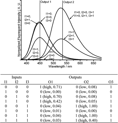 | ||
| Fig. 11 Three-input combinatorial logic functions. (Top) Fluorescent changes (λex = 350 nm) for DMPTE (0.02 mmol L−1) in dichloromethane. (Bottom) The truth table for the logic gates. Inputs: 0.06 mmol L−1CuCl2 (I1), 0.12 mmol L−1TEAB (I2) and 0.12 mol L−1TFA (I3). Outputs: fluorescence intensity at 450 nm (O1), 535 nm (O2) and the sum of fluorescence intensities at both 450 and 535 nm (O3), respectively. | ||
TEAB can be replaced with TEA, which leads to a different combinatorial logic expression. When the input signal of protons is absent (I3 = 0), the input signals of cupric ion (I1) and TEA (I2) also produce an IMPLICATION logic gate (O1) and a PASS 0 logic gate (O2) at 450 and 535 nm, respectively. The co-existence of TEA and protons (I1 = 0, I2 = I3 = 1) leads to neutralization, producing only the fluorescence emission at 450 nm (O1 = 1, O2 = 0). When cupric ion, TEA and protons are all present (I1 = I2 = I3 = 1), the fluorescence of DMPTE is quenched by the cupric ion with low fluorescent intensities at both wavelengths (O1 = O2 = 0) (Fig. 12 and Fig. S14 in ESI†). An EnNOR logic function is realized at the 535 nm (O2). The sum of the fluorescent intensities at both channels produces the third output signal (O3). Then another logic circuit with three inputs and three outputs is realized.
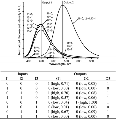 | ||
| Fig. 12 Three-input combinatorial logic functions. (Top) Fluorescence changes (λex = 350 nm) for DMPTE (0.02 mmol L−1) in dichloromethane. (Bottom) The truth table for the logic gates. Inputs: 0.06 mmol L−1CuCl2 (I1), 0.11 mol L−1TEA (I2) and 0.12 mol L−1TFA (I3). Outputs: fluorescence intensity at 450 nm (O1), 535 nm (O2) and the sum of fluorescence intensities at both 450 and 535 nm (O3), respectively. | ||
Molecular keypad lock
The multiple recognition capacity of DMPTE can also be utilized to distinguish different input sequences, and thus serves as a molecular keypad lock to authenticate three-digit password entries. The dichloromethane solution of DMPTE (0.02 mmol L−1) in presence of TEA (0.11 mmol L−1) is employed as the initial state. The input signals are introduced through a keypad, in which keys are linked with different chemical-encoded inputs or photo-irradiation, such as TFA (1 eq., denoted as T), TEA (1 eq., denoted as E) and 415 nm excitation (2 min impulse, denoted as L). The output requirement to pass the password authentication is the fluorescence intensity at the 530 nm being above the threshold.When TFA and TEA are added to the solution, the combination of input signals affords three different input states. For the condition of two inputs of TFA, neutral DMPTE can be converted into the diprotonated state H2DMPTE while the other two input combinations can not protonate DMPTE owing to the presence of TEA (0.33 and 0.11 mmol L−1). As the excitation at 415 nm can only trigger the fluorescence emission of H2DMPTE, the input string TTL is the only one to produce the required fluorescence signal above the threshold, as shown in Fig. 13. The reversible acid–base reaction of DMPTE is then encoded with the keypad lock functionalities to authenticate the user’s password entry at the molecular level.
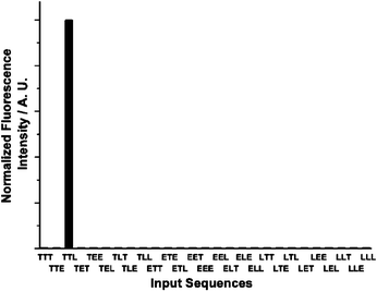 | ||
| Fig. 13 Molecular keypad lock within DMPTE (0.02 mmol L−1 in dichloromethane) in the presence of TEA (0.11 mmol L−1). Inputs: 0.12 mmol L−1TFA (T), 0.11 mmol L−1TEA (E) and 2 min light irradiation at 415 nm (L). Outputs: fluorescence intensity at 530 nm. Threshold value: 0.5. | ||
Conclusions
In the present work, a chemical-sensitive fluorescent molecule DMPTE is applied in the successful construction of various molecular logic gates. Different coordination and protonation states of DMPTE exhibit different fluorescent properties, which are denoted as logic 0 and logic 1 states at varied wavelengths. The various fluorescence changes of the current single molecule in response to the multiple input chemicals are then depicted by the entire set of 2-bit Boolean logic gates, such as PASS 0, PASS 1, YES, NOT, OR, NOR, INHIBIT, IMPLICATION, AND, NAND, XOR, XNOR. The fundamental logic gates are further integrated at the molecular level to construct complex logic circuits, from the reconfigurable 2-bit logic gates to the three-input combinatorial logic circuits. All the logic expressions executed by DMPTE are realized with the same initial state and different choices of the inputs and outputs. Although the current logic functions are operated in solution with the problem of the accumulation of metal ions, the highly integrated logic functions, induced by the multiple ionic reception processes in solution, provides a pathway towards the functional integration in future combinatorial logic circuits and devices working with fluorescent molecules. Based on the sequence-sensitive fluorescence changing behaviors, DMPTE can also serve as a molecular keypad lock to distinguish three-digit input sequences.Acknowledgements
The authors thank the NSFC (20821091, 20771009 and 20731160001) and PKU for financial support.References
- (a) A. P. de Silva, N. D. McClenaghan and C. P. McCoy, Molecular-level electronics, imaging and information, energy and environment, in Electron Transfer in Chemistry, ed. V. Balzani, Wiley-VCH, Weinheim, 2001, vol. 5 Search PubMed; (b) Molecular Devices and Machines. A Journey Into the Nano World, eds. V. Balzani, M. Venturi and A. Credi, Wiley-VCH, Weinheim, 2003 Search PubMed; (c) G. J. Brown, A. P. de Silva and S. Pagliari, Chem. Commun., 2002, 2461 RSC; (d) F. M. Raymo, Adv. Mater., 2002, 14, 401 CrossRef CAS; (e) F. M. Raymo, S. Giordani, A. J. P. White and D. J. Williams, J. Org. Chem., 2003, 68, 4158 CrossRef CAS; (f) A. P. de Silva and N. D. McClenaghan, Chem.–Eur. J., 2004, 10, 574 CrossRef; (g) Z. X. Wang, G. R. Zheng and P. Lu, Org. Lett., 2005, 7, 3669 CrossRef CAS; (h) Z. J. Zhao, Y. J. Xing, Z. X. Wang and P. Lu, Org. Lett., 2007, 9, 547 CrossRef CAS; (i) A. Credi, Angew. Chem., Int. Ed., 2007, 46, 5472 CrossRef CAS; (j) G. Y. Jiang, Y. L. Song, X. F. Guo, D. Q. Zhang and D. B. Zhu, Adv. Mater., 2008, 20, 2888 CrossRef CAS.
- See, for examples: (a) A. P. de Silva, H. Q. N. Gunaratne and C. P. McCoy, Nature, 1993, 364, 42 CrossRef; (b) A. Credi, V. Balzani, S. J. Langford and J. F. Stoddart, J. Am. Chem. Soc., 1997, 119, 2679 CrossRef CAS; (c) A. P. de Solva, H. Q. N. Gunaratne and C. P. McCoy, J. Am. Chem. Soc., 1997, 119, 7891 CrossRef CAS; (d) B. Turfan and E. U. Akkaya, Org. Lett., 2002, 4, 2857 CrossRef CAS; (e) A. P. de Silva, G. D. McClean and S. Pagliari, Chem. Commun., 2003, 2010 RSC; (f) J. F. Callan, A. P. de Silva and N. D. McClenaghan, Chem. Commun., 2004, 2048 RSC; (g) S. Uchiyama, G. D. McClean, K. Iwai and A. P. de Silva, J. Am. Chem. Soc., 2005, 127, 8920 CrossRef CAS; (h) D. C. Magri, G. J. Brown, G. D. McClean and A. P. de Silva, J. Am. Chem. Soc., 2006, 128, 4950 CrossRef CAS; (i) G. X. Zhang, D. Q. Zhang, Y. C. Zhou and D. B. Zhu, J. Org. Chem., 2006, 71, 3970 CrossRef CAS; (j) G. Nishimura, K. Ishizumi, Y. Shiraishi and T. Hirai, J. Phys. Chem. B, 2006, 110, 21596 CrossRef CAS; (k) W. D. Zhou, Y. J. Li, Y. L. Li, H. B. Liu, S. Wang, C. H. Li, M. J. Yuan, X. F. Liu and D. B. Zhu, Chem.–Asian J., 2006, 1–2, 224 CrossRef; (l) E. Perez-Inestrosa, J. M. Montenegro, D. Collado, R. Suau and J. Casado, J. Phys. Chem. C, 2007, 111, 6904 CrossRef CAS; (m) M. Kluciar, R. Ferreira, B. de Castro and U. Pischel, J. Org. Chem., 2008, 73, 6079 CrossRef.
- S. Uchiyama, N. Kawai, A. P. de Silva and K. Iwai, J. Am. Chem. Soc., 2004, 126, 3032 CrossRef CAS.
- (a) M. Biancardo, C. Bignozzi, H. Doyle and G. Redmond, Chem. Commun., 2005, 3918 RSC; (b) Y. C. Zhou, H. Wu, L. Qu, D. Q. Zhang and D. B. Zhu, J. Phys. Chem. B, 2006, 110, 15676 CrossRef CAS; (c) G. Y. Wen, J. Yan, Y. C. Zhou, D. Q. Zhang, L. Q. Mao and D. B. Zhu, Chem. Commun., 2006, 3016 RSC.
- (a) F. Pina, M. J. Melo, M. Maestri, P. Passaniti and V. Balzani, J. Am. Chem. Soc., 2000, 122, 4496 CrossRef CAS; (b) F. M. Raymo and S. Giordani, Proc. Natl. Acad. Sci. USA, 2002, 99, 4941 CrossRef CAS; (c) X. F. Guo, D. Q. Zhang, Y. C. Zhou and D. B. Zhu, J. Org. Chem., 2003, 68, 5681 CrossRef CAS; (d) H. Tian, B. Qin, R. X. Yao, X. L. Zhao and S. J. Yang, Adv. Mater., 2003, 15, 2104 CrossRef CAS; (e) X. F. Guo, D. Q. Zhang and D. B. Zhu, Adv. Mater., 2004, 16, 125 CrossRef CAS; (f) S. D. Straight, P. J. Andréasson, G. Kodis, S. Bandyspadhyay, R. H. Mitchell, T. A. Moore, A. L. Moore and D. Gust, J. Am. Chem. Soc., 2005, 127, 9403 CrossRef CAS; (g) J. Andréasson, Y. Terazono, B. Albinsson, T. A. Moore, A. L. Moore and D. Gust, Angew. Chem., Int. Ed., 2005, 44, 7591 CrossRef; (h) D. Gust, T. A. Moore and A. L. Moore, Chem. Commun., 2006, 1169 RSC; (i) D. H. Qu, F. Y. Ji, Q. C. Wang and H. Tian, Adv. Mater., 2006, 18, 2035 CrossRef CAS; (j) H. Zhang, X. K. Lin, Y. Yan and L. X. Wu, Chem. Commun., 2006, 4575 RSC; (k) J. Andréasson, S. D. Straight, S. Bandyopadhyay, R. H. Mitchell, T. A. Moore, A. L. Moore and D. Gust, Angew. Chem., Int. Ed., 2007, 46, 958 CrossRef CAS; (l) S. D. Straight, P. A. Liddell, Y. Terazono, T. A. Moore, A. L. Moore and D. Gust, Adv. Funct. Mater., 2007, 17, 777 CrossRef CAS.
- A. P. de Silva, Nat. Mater., 2005, 4, 15 CrossRef CAS.
- (a) H. T. Baytekin and E. U. Akkaya, Org. Lett., 2000, 2, 1725 CrossRef CAS; (b) A. P. de Silva and N. D. McClenaghan, Chem.–Eur. J., 2002, 8, 4935 CrossRef; (c) Y. Shiraishi, Y. Tokitoh and T. Hirai, Chem. Commun., 2005, 5316 RSC; (d) A. P. de Silva and S. Uchiyama, Nat. Nanotechnol., 2007, 2, 399 Search PubMed; (e) Z. X. Li, L. Y. Liao, W. Sun, C. H. Xu, C. Zhang, C. J. Fang and C. H. Yan, J. Phys. Chem. C, 2008, 112, 5190 CrossRef CAS.
- See for examples: (a) F. M. Raymo and S. Giordani, J. Am. Chem. Soc., 2001, 123, 4651 CrossRef CAS; (b) J. M. Montenegro, E. Perez-Inestrosa, D. Collado, Y. Vida and R. Suau, Org. Lett., 2004, 6, 2353 CrossRef; (c) M. de Sousa, B. de Castro, S. Abad, M. A. Miranda and U. Pischel, Chem. Commun., 2006, 2051 RSC; (d) L. Y. Zhao, D. Sui, J. Chai, Y. Wang and S. M. Jiang, J. Phys. Chem. B, 2006, 110, 24299 CrossRef CAS; (e) M. Amelia, M. Baroncini and A. Credi, Angew. Chem., Int. Ed., 2008, 47, 6240 CrossRef CAS.
- (a) A. P. de Silva and N. D. McClenaghan, J. Am. Chem. Soc., 2000, 122, 3965 CrossRef CAS; (b) M. N. Stojanovic and D. Stefanovic, J. Am. Chem. Soc., 2003, 125, 6673 CrossRef CAS; (c) A. Okamoto, K. Tanaka and I. Saito, J. Am. Chem. Soc., 2004, 126, 9458 CrossRef CAS; (d) X. F. Guo, D. Q. Zhang, G. X. Zhang and D. B. Zhu, J. Phys. Chem. B, 2004, 108, 11942 CrossRef CAS; (e) D. H. Qu, Q. C. Wang and H. Tian, Angew. Chem., Int. Ed., 2005, 44, 5296 CrossRef CAS; (f) J. Andréasson, G. Kodis, Y. Terazono, P. A. Liddell, S. Bandyopadhyay, R. H. Mitchell, T. A. Moore, A. L. Moore and D. Gust, J. Am. Chem. Soc., 2004, 126, 15926 CrossRef CAS; (g) F. Remacle, R. Weinkauf and R. D. Levine, J. Phys. Chem. A, 2006, 110, 177 CrossRef CAS; (h) Y. C. Zhou, H. Wu, L. Qu, D. Q. Zhang and D. B. Zhu, J. Phys. Chem. B, 2006, 110, 15677; (i) J. Andréasson, S. D. Straight, G. Kodis, C. D. Park, M. Hambourger, M. Gervaldo, B. Albiinsson, T. Moore, A. Moore and D. Gust, J. Am. Chem. Soc., 2006, 128, 16259 CrossRef CAS; (j) L. Zhang, W. A. Whitfield and L. Zhu, Chem. Commun., 2008, 1880 RSC.
- (a) S. J. Langford and T. Yann, J. Am. Chem. Soc., 2003, 125, 11198 CrossRef CAS; (b) A. Coskun, E. Deniz and E. U. Akkaya, Org. Lett., 2005, 7, 5187 CrossRef CAS; (c) F. Y. Li, M. Shi, C. H. Huang and L. P. Jin, J. Mater. Chem., 2005, 15, 3015 RSC; (d) M. Suresh, D. A. Jose and A. Das, Org. Lett., 2007, 9, 441 CrossRef CAS; (e) U. Pishel and B. Heller, New J. Chem., 2008, 32, 395 RSC; (f) Z. Q. Guo, P. Zhao, W. H. Zhu, X. M. Huang, Y. S. Xie and H. Tian, J. Phys. Chem. C, 2008, 112, 7047 CrossRef CAS.
- (a) F. Remacle, S. Speiser and R. D. Levine, J. Phys. Chem. B, 2001, 105, 5589 CrossRef CAS; (b) D. Margulies, G. Melman, C. E. Felder, R. Arad-Yellin and A. Shanzer, J. Am. Chem. Soc., 2004, 124, 15400 CrossRef; (c) D. Margulies, G. Melman and A. Shanzer, Nat. Mater., 2005, 4, 768 CrossRef CAS; (d) D. Margulies, G. Melman and A. Shanzer, J. Am. Chem. Soc., 2006, 128, 4865 CrossRef CAS; (e) Y. Liu, W. Jiang, H. Y. Zhang and C. J. Li, J. Phys. Chem. B, 2006, 110, 14231 CrossRef CAS; (f) U. Pishel, Angew. Chem., Int. Ed., 2007, 46, 4026 CrossRef CAS , and references therein; (g) W. Sun, Y. R. Zheng, C. H. Xu, C. J. Fang and C. H. Yan, J. Phys. Chem. C, 2007, 111, 11706 CrossRef CAS.
- (a) D. Margulies, C. E. Felder, G. Melman and A. Shanzer, J. Am. Chem. Soc., 2007, 129, 347 CrossRef CAS; (b) Z. Q. Guo, W. H. Zhu, L. J. Shen and H. Tian, Angew. Chem., Int. Ed., 2007, 46, 5549 CrossRef CAS; (c) G. Strack, M. Ornatska, M. Pita and E. Katz, J. Am. Chem. Soc., 2008, 130, 4234 CrossRef CAS; (d) W. Sun, C. Zhou, C. H. Xu, C. J. Fang, C. Zhang, Z. X. Li and C. H. Yan, Chem.–Eur. J., 2008, 14, 6342 CrossRef CAS; (e) J. Andréasson, S. D. Straight, T. A. Moore, A. L. Moore and D. Gust, J. Am. Chem. Soc., 2008, 130, 11122 CrossRef CAS.
- A. P. de Silva, B. McCaughan, B. O. F. McKinney and M. Querol, Dalton Trans., 2003, 1902 RSC.
- (a) A. P. de Silva, H. Q. N. Gunaratne, T. Gunnlaugsson, A. J. M. Huxley, C. P. McCoy, J. T. Pademacher and T. E. Rice, Chem. Rev., 1997, 97, 1515 CrossRef; (b) A. E. Bruno, S. Barnard, M. Rouilly, A. Waldner, J. Berger and M. Ehrat, Anal. Chem., 1997, 69, 507 CrossRef CAS; (c) J. S. Yang and T. M. Swager, J. Am. Chem. Soc., 1998, 120, 11864 CrossRef CAS; (d) R. A. Agbaria, P. B. Oldham, M. McCarrol, L. B. McGown and I. M. Warner, Anal. Chem., 2002, 74, 3952 CrossRef CAS; (e) Z. F. Fei, N. Kocher, C. J. Mohrschladt, H. Ihmels and D. Stalke, Angew. Chem., Int. Ed., 2003, 42, 783 CrossRef CAS; (f) D. A. Leigh, M. A. F. Morales, E. M. Pérez, J. K. Y. Wong, C. G. Saiz, A. M. Z. Slawin, A. J. Carmichael, D. M. Haddleton, A. M. Brouwer, W. J. Buma, G. W. H. Wurpel, S. León and F. Zerbetto, Angew. Chem., Int. Ed., 2005, 44, 3062 CrossRef CAS; (g) A. P. de Silva, M. R. James, B. D. Mckinney, D. A. Pears and S. M. Weir, Nat. Mater., 2006, 5, 787 CrossRef.
- C. J. Fang, Z. Zhu, W. Sun, C. H. Xu and C. H. Yan, New J. Chem., 2007, 31, 580 RSC.
- N. Shao, J. Y. Jin, S. M. Cheung, R. H. Tang, W. H. Chan and T. Mo, Angew. Chem., Int. Ed., 2006, 45, 4944 CrossRef CAS.
- M. H. Zheng, J. Y. Jin, W. Sun and C. H. Yan, New J. Chem., 2006, 30, 1192 RSC.
Footnote |
| † Electronic supplementary information (ESI) available: Results of fluorescence titration experiment of DMPTE with Cu2+ or Ce4+, fluorescence spectra of DMPTE in the presence of several other chemical inputs, and digital circuits for the molecular logic functions described in the article. See DOI: 10.1039/b817098c |
| This journal is © The Royal Society of Chemistry and the Centre National de la Recherche Scientifique 2009 |
