A new mixed-matrix membrane for DMFCs
Received
13th May 2009
, Accepted 13th August 2009
First published on
7th September 2009
Broader context
Direct methanol fuel cells (DMFCs) have reached a high level of development and are now almost universally referred to as the sixth-fuel-cell type. In terms of applications, they are set to function as power sources for a range of mobile applications, a situation brought about by the convenience of storage of liquid fuel. For an expansion of the applications of DMFCs, efforts are being expended to develop improved and cost-effective polymer-electrolyte membranes that would mitigate methanol cross-over from the anode to the cathode. It is desirable that these membranes comprise non-hazardous chemicals. Accordingly, this study is an attempt to realise a membrane electrolyte from natural precursors such that the process generates little toxicity to the environment. The polymer electrolyte membrane, derived from naturally abundant chitosan (CS) and hydroxy ethyl cellulose (HEC), possesses good methanol-barrier properties and exhibits high proton-conductivity, the pre-requisites required for a membrane to be used in DMFCs. Stabilised salt of phosphotungstic acid (PTA) is incorporated to the CS-HEC blend to enhance the proton conductivity of the membrane. Preferential water-sorption characteristics of the CS-HEC-PTA mixed matrix play an important role in ameliorating the DMFC performance.
|
Introduction
The promise of direct methanol fuel cells (DMFCs) to complement/substitute the existing batteries is being realised along with their potential as the future technology for mobile and portable power applications.1,2 A critical component of DMFCs is the polymer electrolyte membrane which acts as a physical separator between anode and cathode allowing the protons generated during the methanol oxidation to move to the cathode.3,4 It is desirable that, besides high proton-conductivity, the membrane should exhibit low-methanol cross-over with high chemical and mechanical stability in conjunction with its cost-effectivity and ease of production. In the literature, both perfluorinated sulfonic acid polymer and non-fluorinated polymer membranes have been used as membrane electrolyte in DMFCs.5–9 Among these, the former are highly cost intensive as well as prone to methanol permeability. The latter affects the DMFC performance by reducing the electrode potential due to methanol oxidation at the cathode and in turn decreases the fuel efficiency. It is reported that up to 40% of the methanol could be lost in DMFCs due to cross-over from anode to cathode.10 In the light of the foregoing, intensive R & D efforts are being expended towards modification of fluorinated and non-fluorinated membranes to minimize methanol cross-over in DMFCs.11,12
Chitosan (CS)-based natural polymeric composites are reported to reduce methanol cross-over in DMFCs.13–17 CS is the deacetylated form of chitin, the second most abundant biopolymer in nature, and finds applications as membrane material in ultrafiltration, reverse osmosis, pervaporation and lithium-ion batteries.18–21 CS has both reactive amino and hydroxyl groups that can participate in the preferential water sorption. Phosphotungstic acid (PTA), a heteropoly acid, exhibits strong Brønsted acidity and proton conductivity as high as 1.9 × 10⁻¹ S cm−1 at 303 K.22 The strong acidity of PTA arises from the presence of polyanion [PW12O40]3− as also due to the limited distribution of its negative charge over its outer surface. Earlier investigations showed that protons in PTA dissociate independently in solutions with acidic sites bearing the same strength.23 However, PTA super acid is highly soluble in water when incorporated with CS to form a mixed-matrix membrane. PTA also has the tendency to leach out from the membrane, which limits its long-term use in DMFCs.14
In the present study, preparation of a natural polymeric membrane is accomplished using environment-friendly chemicals. The mechanical and hydrophilic properties of CS are improved by blending it with water-soluble non-ionic polymers, namely hydroxy ethyl cellulose (HEC). The blend membrane is highly hydrophilic and possesses selective water sorption properties.24,25 In order to promote proton conductivity and methanol-barrier property, the CS-HEC blend is modified with cesium-stabilized PTA to realise a mixed-matrix membrane. Substituting the protons of PTA with cesium (Cs) increases the surface area from 5 m2/g to a value >100 m2/g due to the submicron particle-size of Cs-stabilized PTA.26 The stabilised form of PTA is uniformly dispersed over the CS-HEC matrix because of its high surface-area. Partially-exchanged PTA with cesium salt is stable in aqueous medium and is compatible for application in DMFCs.
Experimental
Chitosan (CS) with a degree of deacytelization >95%, hydroxy ethyl cellulose (HEC), phosphotungstic acid (PTA) (mol. wt. = 6499 g/mol) and cesium carbonate were procured from Aldrich Chemicals. Glacial acetic acid and sulfuric acid were procured from Rankem Chemicals, India. All chemicals were used as-received. Toray TGP-H-120 was procured from E-Tek (US). Vulcan XC-72R carbon was procured from Cabot Corporation (US). Pt–Ru (60 wt. % in 1:1 atomic ratio) and Pt/C (40 wt. % Pt on Vulcan XC-72R carbon) were obtained from Alfa Aesar (Johnson Matthey). Deionised (DI) water (18.4 MΩ cm) from Millipore was used during the experiments.
Stabilization of PTA
PTA was stabilized with stoichiometric amounts of cesium carbonate in deionised water similarly to the procedure described elsewhere.27 The transparent, homogenous PTA solution turned cloudy white as it precipitated out on ion-exchanging the protons with the larger cations present in the cesium carbonate solution. The resulting admixture was sonicated in an ultrasonic bath for 4 h and allowed to dry in an air-oven at 303 K. PTA thus obtained was heat-treated at 623 K for 3 h and grounded to fine powder. Since PTA is a tribasic acid, attempts were made to control the number of protons substituted by controlling the stoichiometry of the added salt solution, namely Cs:PTA in 1:0.5 molar ratio, enabling one H+-ion from the PTA to exchange with cesium to stabilize it in the aqueous/acidic medium.
CS-HEC-PTA mixed-matrix membranes were prepared by a solution-casting technique. In brief, 70 ml of 1.3 wt. % CS aqueous solution was prepared by dissolving the required amount of CS in 10 wt. % acetic acid at 303 K followed by its mechanical stirring until a clear solution was obtained. Similarly, 20 ml of 25 wt. % HEC relative to CS was dissolved in 10 wt. % acetic acid at 303 K followed by its stirring until a homogeneous solution was obtained. Both the solutions were mixed together and stirred for 3–4 h to form a compatible blend. A required quantity of stabilized PTA (1 to 5 wt. % with respect to the CS-HEC blend) was dispersed in 10 wt. % acetic acid under ultra-sonication for 2 h. The resulting solution was added drop wise to the above CS-HEC blend solution under continuous stirring for 24 h. The resulting solution was cast as a membrane on a flat Plexiglass plate by evaporating the solvent at room temperature (∼303 K). CS-HEC blend membranes were prepared in a similar manner without addition of PTA. The membranes were peeled off from the plate after drying and were immersed in 1 M H2SO4 solution for 4 h at room temperature (∼303 K) for further doping and cross-linking, followed by copious washing with DI water to expel any residual H2SO4. The thickness of the membranes was ∼150 µm. The addition of stabilized PTA into the CS-HEC polymer matrix was restricted to 5 wt. % due to the membrane brittleness.
Sorption and proton-conductivity measurements
For sorption measurements, circularly cut (diameter = 2.5 cm) Nafion-117, CS-HEC blend and CS-HEC-Cs-stabilized PTA mixed-matrix membranes were dipped separately in deionised water for 24 h to attain equilibrium. The membranes were surface dried with a tissue paper and initial mass values were recorded on a single-pan digital microbalance (Sartorius, Germany) within an accuracy of ± 0.01 mg. The membranes were then dried in a hot air oven at 333 K for 12 h and their respective weights were measured. Water Sorption values for the aforesaid membranes were calculated using:| |  | (1) |
where W∞ and Wo refer to the weights of sorbed and dry membranes, respectively.
In the case of the methanol sorption measurement, pre-weighed dry membranes (Wo) were dipped in methanol for 24 h to attain equilibrium. The equilibrated membranes were surface blotted and final weights (W∞) were recorded at ambient temperature and methanol sorption was calculated using above equation.
Proton conductivity measurements were performed on Nafion-117, CS-HEC blend and CS-HEC-PTA mixed-matrix membranes in a two-probe cell by an AC impedance technique. The conductivity cell comprised two stainless-steel electrodes, each of 20 mm diameter. The membrane sample was sandwiched between these two electrodes mounted in a teflon block and kept in a closed glass-container. The ionic conductivity data for the membranes were obtained under fully-humidified conditions (100%) by keeping deionized water at the bottom of the test container and equilibrating it for ∼24 h. Subsequently, conductivity measurements were conducted between 303 K and 373 K in a glass container with the provision to heat. The temperature was constantly monitored with a thermometer kept inside the container adjacent to the membrane. AC impedance spectra of the membranes were recorded in the frequency range between 1 MHz and 10 Hz with 10 mV amplitude using a Autolab PGSTAT 30. The resistance (R) of the membrane was determined from the high-frequency intercept of the impedance with the real axis and the membrane conductivity was calculated from the membrane resistance, R, from:
| |  | (2) |
where σ is the
proton conductivity of the
membrane in S/cm,
l is the
membrane thickness in centimetres and
A is the cross-sectional area of the
membranes in cm
2.
Physicochemical characterization
Universal testing machine (UTM) (Model AGS-J, Shimadzu) with an operating head-load of 10 kN was used to study the mechanical properties of the membranes. Cross-sectional area of the sample was obtained from the width and thickness of the membrane sample. The test samples were prepared in the form of dumb-bell shaped object as per ASTM D-882 standards. The membranes were then placed in the sample holder of the machine. The film was stretched at a cross-head speed of 1 mm/min and its tensile strength was estimated using:| | 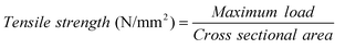 | (3) |
Surface micrographs for CS-HEC blend and CS-HEC-PTA mixed-matrix membranes were obtained using a JEOL JSM 35CF Scanning Electron Microscope (SEM). A gold film of thickness < 100 nm was sputtered on the membrane surfaces, using a JEOL Fine Coat Ion Sputter-JFC-1100 unit, prior to their examination under SEM. Thermo-gravimetric analysis (TGA) for CS-HEC blend and CS-HEC-PTA mixed-matrix membranes were conducted using a SDT Q600 V8.2 TGA/DTA instrument in the temperature range between 273 K and 973 K at a heating rate of 293 K/min with nitrogen flushed at 200 mL/min. The FTIR spectra for CS-HEC blend and CS-HEC-PTA mixed-matrix membranes were obtained using a Nicolet IR 860 spectrometer (Thermo Nicolet Nexus-670) in the frequency range between 4000 and 400 cm−1.
Methanol cross-over studies
In-situ methanol cross-over studies from anode to cathode across the polymer electrolyte membranes in the DMFC were carried out at 343 K as reported in the literature.9,28 At the cathode, the crossed-over methanol was oxidized catalytically by a reaction with oxygen at the catalyst surface. The amount of crossed-over methanol was analyzed gravimetrically by monitoring CO2 at the cathode exhausts. For this purpose, CO2 from the cathode outlet was passed through a clear but saturated barium hydroxide Ba(OH)2 solution leading to the formation of barium carbonate (BaCO3) precipitate according to the reaction:| | | CO2 + Ba(OH)2 → BaCO3↓ + H2O | (4) |
The BaCO3 precipitate was separated from the liquid by a centrifuge, washed with deionised water and subsequently dried at 343 K for 24 h. After cooling to room temperature, it was weighed in a precision balance. The transport of methanol across the membrane from anode to cathode in a DMFC was visualized in terms of a methanol-permeation current. The methanol cross-over current ipmt (MeOH) for the permeated methanol from anode to cathode was obtained using:
| |  | (5) |
The term on the right-hand side of Eq. (5) refers to the equivalent current of the total CO2 flux collected at the cathode exhaust, F represents the Faraday constant, (WBaCO3)c is the dry BaCO3 weight collected at the cathode exhaust in 1 h (mg/h), A is the electrode area (cm2) of the cell and MBaCO3is the molecular weight of BaCO3. The aforesaid procedure was repeated at different load current-densities and the corresponding methanol cross-over rates were determined from the methanol permeation current.
Membrane-performance evaluation in DMFC
The aforesaid membranes were performance evaluated in a DMFC by making membrane electrode assemblies (MEAs). In brief, both the anode and cathode comprised a backing layer, a gas-diffusion layer (GDL) and a reaction layer. Teflonised Toray carbon papers (thickness = 0.38 mm) were employed as the backing layers for these electrodes. A diffusion layer comprising 1.5 mg/cm2 of Vulcan XC-72R carbon slurry dispersed in cyclohexane was applied onto the backing layers followed by sintering in a muffle furnace at 623 K for 30 min. 60 wt. % Pt–Ru (1:1 atomic ratio) supported on Vulcan XC-72R carbon mixed with binder and coated on to one of the GDL constituted the catalyst layer on the anode, while 40 wt. % Pt catalyst supported on Vulcan XC-72R carbon mixed with binder coated on to the other GDL constituted the catalyst layer on the cathode. The catalyst loading on both the anode and cathode was kept at 2 mg/cm2. The active area for the DMFC was 4 cm2. MEAs with Nafion-117 and CS-HEC-PTA mixed-matrix membranes were obtained by hot pressing at 15 kN (∼60 kg/cm2) at 353 K for 2 min. MEAs were evaluated using a conventional fuel cell fixture with parallel serpentine flow-field machined on graphite plates. The cells were tested at 343 K with 2 M aqueous methanol under a flow rate of 2 mL/min at the anode side and oxygen at the cathode side under a flow rate of 300 mL/min at atmospheric pressure. Measurements of cell potential as a function of current density were conducted galvanostatically using a Fuel Cell Test Station (Model PEM-FCTS-158541) procured from Arbin Instruments (US).
Results and discussion
Sorption
Liquid sorption through polymeric membranes has been well documented in the literature.8,29 Sorption data for Nafion-117 membrane, CS-HEC blend and CS-HEC-stablized PTA (1, 3 and 5 wt. %) mixed matrices at 343 K in water and methanol are presented in Fig. 1. It is noteworthy that sorption for CS-HEC-stabilized PTA mixed-matrix membranes in water increases with increasing amounts of PTA from 1 wt. % to 5 wt. %. For the Nafion-117 membrane, water sorption is lower while methanol sorption is higher due to the presence of hydrophilic pendent chains as also due to the availability of the hydrophobic fluorinated backbone.30 It is noteworthy that methanol sorption for CS-HEC-PTA mixed-matrix membranes decreases with increasing PTA content possibly due to the presence of PTA as a filler material. By contrast, due to the dual hydrophilic interactions between the blend and PTA, the water sorption increases and reaches a steady state at about 5 wt. % PTA for the CS-HEC blend. This is in agreement with the literature wherein hydrated phases of PTA vary between 30 and 6 water molecules per PTA molecule.31,32 These results suggest that the CS-HEC-PTA mixed-matrix membrane can act as a methanol barrier in DMFCs.
 |
| | Fig. 1 Sorption (g/g) for Nafion-117, CS-HEC blend and CS-HEC-Cs-stabilized PTA (1, 3 and 5 wt. %). Symbols: (filled bars) Water sorption; (open bars) Methanol sorption. | |
Proton conductivity
Proton transport occurs by the Grötthus and vehicular mechanisms where the protons jump from one solvent molecule to the other through hydrogen bonds, or diffuse together with solvent molecules.33 The proton conductivity for all the membranes increases when increasing the temperature. The maximum proton-conductivity observed for the CS-HEC blend membrane is 2.7 × 10⁻³ S/cm at 343 K. The proton conductivity of the CS-HEC-PTA mixed-matrix membrane is 5.9 × 10⁻³ S/cm, which is higher than the value for the blend-membrane without PTA. It is noteworthy that the CS-HEC-3 wt. % PTA mixed-matrix membrane exhibits higher proton conductivity than CS-HEC-1 wt. % PTA and CS-HEC-5 wt. % PTA membranes. Sorption characteristics have an influence on membrane conductivity as higher water sorption facilitates proton transport through the membrane leading to faster proton conduction. In the CS-HEC-1 wt. % PTA mixed-matrix membrane, the protons available in PTA take maximum advantage of polymeric voids of the CS-HEC matrix to exhibit higher proton conductivity. It is noteworthy that the proton conductivity of the CS-HEC-3 wt. % PTA mixed-matrix membrane is higher than the former membrane due to the higher PTA content, which ameliorates the hydrophilicity by forming hydrogen bonds between the CS-HEC blend and the [PW12O40]3− anion. By contrast, the CS-HEC-5 wt. % PTA mixed-matrix membrane exhibits a lower proton conductivity. This may be due to the excess PTA content, which disrupts the proton conduction path by blocking the voids of the CS-HEC matrix due to presence of the larger Keggin anion.
All the membranes exhibit an Arrhenius-type temperature dependence of the proton conductivity, suggesting a thermally-activated process. The activation energy, which is the minimum energy required for proton transport, is obtained from the slope of the Arrhenius plots using:
where σ is the
proton conductivity in S/cm, σ
0 is the pre-exponential factor,
Ea is the
activation energy in kJ/mol,
R is the universal gas constant (8.314 J/mol K), and
T is the absolute temperature (K).
As the proton conductivity is thermally activated, the conductivity increases with increasing temperature as shown in Fig. 2. From the data, Ea value for the CS-HEC blend membrane is found to be 32.33 kJ/mol, which is higher than the Ea values of 22.5 kJ/mol and 28.41 kJ/mol observed for CS-HEC-3 wt. % PTA and CS-HEC-5 wt. % PTA mixed-matrix membranes, respectively. This suggests that Ea for proton conduction decreases with the introduction of PTA in the CS-HEC matrix. The smaller activation energy values observed for the CS-HEC-PTA mixed-matrix membranes in relation to CS-HEC blend membrane facilitates more protons to readily transfer through the mixed-matrix membrane;34 an Ea value of 15.22 kJ/mol is observed for the Nafion-117 membrane.
 |
| | Fig. 2 lnσ vs. 1000/T. Symbols: (×) CS-HEC blend; (○) CS-HEC Cs-stabilized PTA (1 wt. %) mixed-matrix membrane; (■) CS-HEC-Cs-stabilized PTA (3 wt. %) mixed-matrix membrane; (□) CS-HEC-Cs-stabilized PTA (5 wt. %) mixed- matrix membrane; (●) Nafion-117 membrane. | |
Mechanical stability
Fig. 3 depicts mechanical properties of all the membranes studied here by determining the tensile strength and the elongation-at-break. The data suggest that the tensile strength for the CS-HEC membranes increases with increasing PTA content in the CS-HEC matrix from 1 wt. % to 5 wt. %. The introduction of PTA to CS-HEC restricts the chain segmental mobility and increases the membrane strength. However, due to high chain-segmental-mobility, the CS-HEC blend membrane exhibits lower elongation-at-break compared to the mixed-matrix membranes. By contrast, elongation-at-break for the CS-HEC-5 wt. % PTA membrane decreases due to the semi-brittle nature of the membrane. It is noteworthy that tensile strength and elongation-at-break for the mixed-matrix membranes of CS-HEC-PTA are lower than for the Nafion-117 membrane. Natural CS-HEC polymeric chains interacting with stabilized PTA increase the rigidity of the mixed-matrix membrane reducing tensile strength and elongation-at-break in relation to the Nafion-117 membrane.
 |
| | Fig. 3 Tensile strength and elongation-at-break for Nafion-117, CS-HEC blend and CS-HEC-Cs-stabilized PTA (1,3 and 5 wt%) mixed-matrix membranes. | |
 |
| | Fig. 4 Surface SEM micrographs for (a) CS-HEC blend and (b) CS-HEC-Cs-stabilized PTA (3 wt. %) mixed- matrix membrane. | |
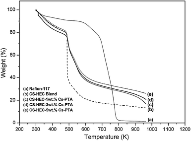 |
| | Fig. 5 TGA plots for Nafion-117, CS-HEC blend, CS-HEC Cs-stabilized PTA (1 wt. %) mixed-matrix membrane; CS-HEC-Cs-stabilized PTA (3 wt. %) mixed-matrix membrane; CS-HEC-Cs-stabilized PTA (5 wt. %) mixed- matrix membrane. | |
![[double bond, length as m-dash]](https://www.rsc.org/images/entities/char_e001.gif) O cross-linking unit in the CS-HEC blend membrane. Prominent peaks occurring at 3430 cm−1 and 2923 cm−1 are assigned to O–H and N–H stretching modes present in CS. Weak stretching bands of C–H and amide bands are merged and appear as a single broad band at 2068 cm−1; this peak shifts from 2068 cm−1 to 2085 cm−1 for PTA incorporated mixed-matrix membranes suggesting the specific interaction of the Keggin cage with the polymer backbone. Most of the characteristic peaks of the Keggin structure in mixed-matrix membranes are blocked due to the interference of CS-HEC. Characteristic peaks of the Keggin anion at 985 cm−1, 890 cm−1 and 800 cm−1 appear as shoulders and merge forming a broad band at 899 cm−1. The distinct peak due to the WOt band at 980 cm−1 is suppressed, indicating the protons in PTA being partially substituted by Cs atoms. Prominent peaks with increased intensity are observed at 1064 cm−1 and 1117 cm−1 due to the asymmetric stretching vibrations of the central PO4 tetrahedron of the Keggins structure in stabilized PTA, as shown in Fig. 6 (b).37 The peaks assigned for both bending mode of the W–Ob–W bridging bond and stretching vibration of the WOt terminal bond are blue shifted from 1310 cm−1 to 1417 cm−1, which is attributed to the columbic interaction between hydroxyl groups of CS-HEC and stabilized PTA.38 The presence of these characteristic peaks indicates that the Keggin geometry is preserved in the mixed-matrix membranes. The up shifts observed in case of W–Ob–W and WOt vibration in PTA are attributed to the increased anion-anion interactions and the increased distance between oxygens of neighbouring [PW12O40]3− anions, where pure W–Od stretching shows a shift in the wave number.39
O cross-linking unit in the CS-HEC blend membrane. Prominent peaks occurring at 3430 cm−1 and 2923 cm−1 are assigned to O–H and N–H stretching modes present in CS. Weak stretching bands of C–H and amide bands are merged and appear as a single broad band at 2068 cm−1; this peak shifts from 2068 cm−1 to 2085 cm−1 for PTA incorporated mixed-matrix membranes suggesting the specific interaction of the Keggin cage with the polymer backbone. Most of the characteristic peaks of the Keggin structure in mixed-matrix membranes are blocked due to the interference of CS-HEC. Characteristic peaks of the Keggin anion at 985 cm−1, 890 cm−1 and 800 cm−1 appear as shoulders and merge forming a broad band at 899 cm−1. The distinct peak due to the WOt band at 980 cm−1 is suppressed, indicating the protons in PTA being partially substituted by Cs atoms. Prominent peaks with increased intensity are observed at 1064 cm−1 and 1117 cm−1 due to the asymmetric stretching vibrations of the central PO4 tetrahedron of the Keggins structure in stabilized PTA, as shown in Fig. 6 (b).37 The peaks assigned for both bending mode of the W–Ob–W bridging bond and stretching vibration of the WOt terminal bond are blue shifted from 1310 cm−1 to 1417 cm−1, which is attributed to the columbic interaction between hydroxyl groups of CS-HEC and stabilized PTA.38 The presence of these characteristic peaks indicates that the Keggin geometry is preserved in the mixed-matrix membranes. The up shifts observed in case of W–Ob–W and WOt vibration in PTA are attributed to the increased anion-anion interactions and the increased distance between oxygens of neighbouring [PW12O40]3− anions, where pure W–Od stretching shows a shift in the wave number.39
Methanol cross-over
Fig. 7 shows the methanol cross-over data for Nafion-117 and CS-HEC-3 wt. % PTA mixed-matrix membranes at 343 K. It is obvious that the methanol cross-over rate decreases with increasing load current-density for both the membranes. By contrast, the methanol cross-over rate for the CS-HEC-PTA mixed-matrix membrane is reduced compared to the Nafion-117 membrane both under open circuit voltage conditions and at varying load current-densities. It is noteworthy that the CS-HEC-PTA mixed-matrix membrane has higher affinity towards water than methanol, compared to the Nafion-117 membrane, which is favourable for prolonged operation of DMFCs. This feature is attributed to the higher hydrophilicity of the CS-HEC-PTA mixed-matrix membrane that favours the selective sorption of water from a methanol-water mixture. Such preferential sorption of water is related to the pervaporation mechanism observed for most of the aqueous-organic mixtures through CS-HEC blend membranes.24 When stabilized PTA is incorporated in to CS-HEC blend, its hydrophilicity is further enhanced reducing the methanol sorption through mixed matrices. The bigger molecular size and less polarity of the methanol molecule compared to water also helps in restricting methanol permeability through the mixed-matrix membrane in DMFCs. This can be visualized from Scheme 1. At higher load current-densities methanol utilization is found to be higher at the anode restricting the methanol to crossover to the cathode side through the mixed-matrices in DMFCs.
 |
| | Fig. 7 Methanol cross-over rate vs. Current density at 343 K for Nafion-117 membrane and CS-HEC-Cs-stabilized PTA (3 wt.%) mixed-matrix membrane. | |
 |
| | Scheme 1 Schematic representation of preferential water sorption from a methanol-water mixture in CS-HEC-Stabilized PTA mixed matrices. | |
DMFC performance
Fig. 8 presents the DMFC performance data for MEAs comprising Nafion-117 and the optimized CS-HEC-3 wt. % PTA mixed-matrix membranes at 343 K under atmospheric pressure. The peak power-density for Nafion-117 membrane is found to be 80 mW/cm2 at a load current-density of 280 mA/cm2. However, a peak power-density of 58 mW/cm2 at a load current-density of 210 mA/cm2 is observed with an MEA comprising the CS-HEC-3 wt. % PTA mixed-matrix membrane. It is notable that proton conductivity is higher for the Nafion-117 membrane compared to the proton conductivity for the CS-HEC-PTA membrane and, hence, there is a higher power density for the former. By contrast, methanol cross-over is higher for Nafion-117 due to its hydrophobic fluorinated backbone. It is important that the hydrophilic nature of both CS-HEC and PTA prevents the formation of selective voids for methanol transport at the CS-HEC and PTA interface without affecting the free-transfer of protons. Peak power density for the DMFC with CS-HEC-Cs-stabilized PTA is lower than with Nafion-117 due to the lower proton conductivity for the former.
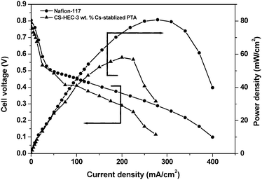 |
| | Fig. 8 Cell voltage and Power density vs. Current density at 343 K for Nafion-117 and CS-HEC-Cs-stabilized PTA (3 wt. %) mixed-matrix membrane. | |
Conclusions
Mixed-matrix membrane comprising CS-HEC-Cs-stabilized PTA with high proton-conductivity and reduced methanol-permeability for DMFCs is prepared using environmentally benign chemicals. Methanol cross-over for the CS-HEC-Cs-stabilized membrane is lower in relation to the Nafion-117 membrane. It is demonstrated that the preferential sorption of water over methanol in water-methanol mixture, brought about by the structural feature of the membrane, is central in limiting methanol permeation across the membrane. In brief, the CS-HEC based membrane reported here uses naturally abundant and cost-effective materials; it is easy to fabricate and is compatible with DMFC applications.
Acknowledgements
Financial support from CSIR, New Delhi is gratefully acknowledged.
References
- N. W. Deluca and Y. A. Elabd, J. Polym. Sci., Part B: Polym. Phys., 2006, 44, 2201–2225 CrossRef CAS.
- V. Neburchilov, J. Martin, H. Wang and J. Zhang, J. Power Sources, 2007, 169, 221–238 CrossRef CAS.
-
H. R. A. Magnet in Handbook of Fuel Cell Technology, ed. C. Berger, Prentice-Hall, Englewood Cliffs, New Jersey, USA, 1967 Search PubMed.
- J. Kjaer, S. Yde-Anderson, N. A. Knudsen and E. Skou, Solid State Ionics, 1991, 46, 169–173 CrossRef CAS.
- M. K. Ravikumar and A. K. Shukla, J. Electrochem. Soc., 1996, 143, 2601–2606 CAS.
- A. Kuver and W. Vielstich, J. Power Sources, 1998, 74, 211–218 CrossRef CAS.
- K. D. Kreuer, J. Membr. Sci., 2001, 185, 29–39 CrossRef CAS.
- A. K. Sahu, G. Selvarani, S. D. Bhat, S. Pitchumani, P. Sridhar, A. K. Shukla, N. Narayan, A. Banarjee and N. Chandrakumar, J. Membr. Sci., 2008, 319, 298–305 CrossRef CAS.
- A. K. Sahu, G. Selvarani, S. Pitchumani, P. Sridhar, A. K. Shukla, N. Narayan, A. Banarjee and N. Chadrakumar, J. Electrochem. Soc., 2008, 155, B686–695 CrossRef CAS.
- P. D. Beatie, F. P. Orfino, V. I. Basura, K. Zychowska, J. Ding, C. Chuy, J. Scmeisser and S. Holdcroft, J. Electroanal. Chem., 2001, 503, 45–56 CrossRef CAS.
- Z. X. Liang, T. S. Zhao and J. Praburam, J. Membr. Sci., 2006, 283, 219–224 CrossRef CAS.
- S. D. Bhat, A. K. Sahu, C. George, S. Pitchumani, P. Sridhar, N. Chandrakumar, K. K. Singh, N. Krishna and A. K. Shukla, J. Membr. Sci., 2009, 340, 73–83 CrossRef CAS.
- P. Mukoma, B. R. Jooste and H. C. M. Vosloo, J. Power Sources, 2004, 136, 1623.
- M. Yamada and I. Honma, Electrochim. Acta, 2005, 50, 2837–2841 CrossRef CAS.
- B. Smitha, S. Sridhar and A. A. Khan, J. Appl. Polym. Sci., 2005, 95, 1154–1163 CrossRef CAS.
- B. Smitha, S. Sridhar and A. A. Khan, Macromolecules, 2004, 37, 2233–2239 CrossRef CAS.
- S. D. Bhat, A. Manokaran, A. K. Sahu, S. Pitchumani, P. Sridhar and A. K. Shukla, J. Appl. Polym. Sci., 2009, 113, 2605–2612 CrossRef CAS.
- H. Matsuyama, Y. Kitamura and Y. Naramura, J. Appl. Polym. Sci., 1999, 72, 397–404 CrossRef CAS.
- C. Tual, E. Espuche, M. Escoubes and A. Domard, J. Polym. Sci., Part B: Polym. Phys., 2000, 38, 1521–1529 CrossRef CAS.
- Y. C. Wei, S. M. Hudson, J. M. Mayer and D. L. Kaplan, J. Polym. Sci., Part A: Polym. Chem., 1992, 30, 2187–2193 CrossRef CAS.
- X. Wang, Z. Shen, F. Zhang and Y. Zhang, J. Membr. Sci., 1996, 119, 191–198 CrossRef CAS.
- O. Nakamura and I. Ogino, Mater. Res. Bull., 1982, 17, 231 CrossRef CAS.
- D. Farcasiu and Jing Qi, J. Catal., 1995, 152, 198–203 CrossRef CAS.
- A. Chanachai, R. Jiratananon, D. Uttapap, G. Y. Moon, W. A. Anderson and R. Y M. Huang, J. Membr. Sci., 2000, 166, 271–280 CrossRef CAS.
- R. Jiratananon, A. Chanachai, R. Y. M. Huang and D. Uttapap, J. Membr. Sci., 2002, 195, 143–151 CrossRef.
- Soled, S. Misceo, G. Mc Vicker, W. E. Gates, A. Guiterrez and J. Paes, Catal. Today, 1997, 36, 441–450 CrossRef CAS.
- V. Ramani, H. R. Kunz and J. M. Fenton, Electrochim. Acta, 2005, 50, 1181–1187 CrossRef CAS.
- R. Jiang and D. Chu, J. Electrochem. Soc., 2004, 151, A69–A76 CrossRef CAS.
-
J. Crank, The Mathematics of Diffusion, 1975, Clarendon Press, Oxford, UK Search PubMed.
- M. S. Kang, J. H. Kim, J. Won, S. H. Moon and Y. S. Kang, J. Membr. Sci., 2005, 247, 127–135 CrossRef CAS.
-
P. Colomban(Ed.), Chemistry of Solid State Materials. 2. Proton Conductors-Solids, Membranes and Gels-Materials and Devices, 1992, Cambridge University Press, Cambridge, UK Search PubMed.
- O. Nakamura, I. Ogino and T. Kodama, Solid State Ionics, 1981, 3, 347–351 CrossRef.
- K. D. Kreuer, Solid State Ionics, 2000, 136, 149–160 CrossRef.
- Z. Cui, C. Liu, T. Lu and W. Xing, J. Power Sources, 2007, 167, 94–99 CrossRef CAS.
- Z. Cui, W. Xing, C. Liu, J. Liao and H. Zhang, J. Power Sources, 2009, 188, 24–29 CrossRef CAS.
- Y. Wan, K. A. M. Creber, B. Peppley and V. T. Bui, J. Appl. Polym. Sci., 2004, 94, 2309–2323 CrossRef CAS.
- M. Helen, B. Viswanathan and S. Srinivasa Murthy, J. Power Sources, 2006, 163, 433–439 CrossRef CAS.
- T. Okuhara, N. Mizuno and M. Misono, Advanced Synth. Catal., 1996, 41, 113–122 Search PubMed.
- C. R. Deltcheff, R. Thouvenot and R. Franck, Spectrochim. Acta, Part A, 1976, 32, 587–597 CrossRef.
|
| This journal is © The Royal Society of Chemistry 2009 |
Click here to see how this site uses Cookies. View our privacy policy here. 