Colour modification action of an upconversion photonic crystal†
Zhen-Xing
Li
,
Le-Le
Li
,
Huan-Ping
Zhou
,
Quan
Yuan
,
Cheng
Chen
,
Ling-Dong
Sun
and
Chun-Hua
Yan
*
Beijing National Laboratory for Molecular Science, State Key Laboratory of Rare Earth Materials Chemistry and Applications, PKU-HKU Joint Laboratory on Rare Earth Materials and Bioinorganic Chemistry, Peking University, Beijing, 100871, China. E-mail: yan@pku.edu.cn; Fax: +86 10 6275 4179; Tel: +86 10 6275 4179
First published on 21st September 2009
Abstract
Colour modification of the upconversion emission has been successfully achieved in a novel upconversion photonic crystal.
According to Moore’s Law, the number of components on an integrated circuit is being doubled approximately every eighteen months, with a subsequent impact on computing power.1 As the electronic components continually get smaller in size, the mutual interference between components is becoming increasingly pronounced.2,3 Therefore, the development of a new generation of information technology components is becoming urgent. Photons are ideal information carriers, instead of electrons in integrated circuits. Photons present several advantages over electrons: travelling faster, carrying a larger amount of information, and reducing the energy loss, because, as they are bosons, they are not as strongly interacting as electrons.4 To completely realize the use of photons as information carriers, it is necessary to create integrated optical circuits to control photons analogous to electronic integrated circuits for the control of electrons. Photonic crystals provide an opportunity to solve this problem. Photonic crystals, first introduced by Yablonovitch5 and John,6 possess highly ordered structures with a periodically modulated refractive index (or dielectric constant), with periods typically on the length scale of optical wavelengths. This periodicity may lead to the formation of a photonic band gap (PBG), a band of frequencies for which light propagation in the photonic crystal is forbidden. Owing to the existence of the PBG, control over the propagation of photons can be achieved by designing and modulating the PBG structure. More importantly, photonic crystals can be functionalized by different photonic components. One such interesting possibility is the modification of the spontaneous emission of photoluminescent guests embedded in photonic crystals.7 To date, there have been several experimental reports on the formation of macroporous photonic crystals and the modification of spontaneous emission of photoluminescent guests, including organic dyes, quantum dots and rare earth ions.8–10 However, the emission bands of fluorescent dyes are often broader than the PBG, and thus only a part of the emission spectrum could be affected by photonic crystal structure.8 In contrast, light emitters with narrow emission bands would be ideal candidates to maximize the photonic crystal effect. Hence, rare earth ions involving f-orbital electrons would be a suitable tool to study the photonic crystal effect, as they have much narrower emission bands than the PBG of typical inverse opal structures (air voids in a silica-doped matrix).
Upconversion (UC) luminescence is an important feature of the optical properties of rare earth compounds, the study of which has grown rapidly owing to their extensive applications in solid-state lasers, three-dimensional (3D) flat-panel displays, optical fiber-based telecommunications and low-intensity IR imaging.11 Among the various UC phosphors, hexagonal-phase NaYF4:Yb,Er is one of the most efficient; however, it is still a challenge to manipulate its UC emission behaviour. Herein, we present a novel UC photonic crystal fabricated by embedding NaYF4:Yb,Er nanoparticles in inverse opals, so as to manipulate the UC emission behaviour. The hexagonal-phase NaYF4:Yb,Er nanoparticles exhibit intense, and fairly narrow red and green emissions. Such a material was shaped into an inverse opal, in which the size of the holes was varied controllably in order to modulate the PBG in different positions and thus to tune the NaYF4:Yb,Er emission behaviour. Besides modification of the lifetime, which has been extensively observed by others,12 we could suppress the spontaneous green emission that is located in the range of the PBG. Such tuning of spontaneous emission provides new possibilities for the design of more efficient devices for colour purification. The fabrication of SiO2 inverse opals embedded with NaYF4:Yb,Er nanoparticles was achieved by simple infiltration of the silica sol doped with NaYF4:Yb,Er nanoparticles into polystyrene (PS) colloidal crystals. First, monodisperse PS colloidal spheres with a diameter of 528 nm (for sample PC1) were assembled into 3D colloidal crystals on a filter membrane. Then, the silica sol doped with NaYF4:Yb,Er nanoparticles was added dropwise to the colloidal crystal film in a Büchner funnel under vacuum, leading to deposition in the interstices of the colloidal crystals. Finally, the resultant samples were calcined at 500 °C for 3 h in air by slowly increasing the temperature from room temperature to 500 °C (1 °C min−1 ramping rate). The fabricated inverse opals PC1 are thin films consisting of air spheres in silica.
According to electromagnetic field theory, the solutions of Maxwell equations in a periodic dielectric medium are used to describe the behaviour of light in photonic crystals. Through mathematical analysis, they can be rewritten in the form:13
 | (1) |
 | (2) |
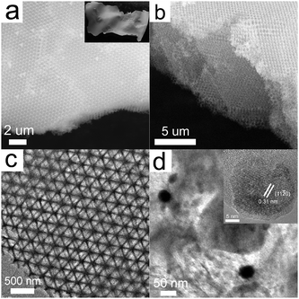
The scanning electron microscopy (SEM) images of PC1 are presented (Fig. 1a and b), which indicate that the obtained sample exhibits a long-range 3D ordered structure comprised of interconnected macropores that form an ordered hexagonal arrangement of air spheres. The inset of Fig. 1a displays a typical photograph of PC1 film taken with a digital camera, and its length is over 2 cm. Fig. 1c shows the transmission electron microscopy (TEM) image of PC1 with macropore arrays viewed from (111) planes. The high-magnification TEM image shows that the NaYF4:Yb,Er nanoparticles are dispersed in the macroporous wall (Fig. 1d). The high-resolution TEM image (the inset in Fig. 1d) also demonstrates that the embedded NaYF4:Yb,Er nanoparticles are of single-crystalline nature enclosed by the (11![[2 with combining macron]](https://www.rsc.org/images/entities/char_0032_0304.gif) 0) plane, and the polyhedron shape is affected by the calcination.
0) plane, and the polyhedron shape is affected by the calcination.
 | ||
| Fig. 1 (a) SEM image of SiO2 inverse opals embedded with NaYF4:Yb,Er nanoparticles (inset: photographic image of the inverse opals). (b) SEM image under a 45° angle showing the thickness of the inverse opals. (c) TEM image of the inverse opals. (d) High-magnification TEM image showing the NaYF4:Yb,Er nanoparticles in the inverse opal wall (inset: HRTEM image of the NaYF4:Yb,Er nanoparticles). | ||
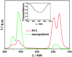
The UC luminescence spectrum of NaYF4:Yb,Er nanoparticles displays two typical emission bands upon excitation with a 980 nm laser diode: at 520–570 nm, attributable to the radiative transitions from (4H11/2, 4S3/2) to 4I15/2 (green, relatively intensive), and at 630–680 nm from 4F9/2 to 4I15/2 (red, relatively weak) of Er3+ (Fig. 2).16 The UC luminescence spectrum of PC1 is also presented in Fig. 2. Interestingly, a relatively intense red emission at about 655 nm was observed, while the intensity of green emission at 520–570 nm decreased sharply. The inset of Fig. 2 clearly shows the presence of a stop band at about 545 nm for the PC1 sample, which compared well with the expected value calculated from eqn (2). More importantly, this PBG matches well with the green emission of NaYF4:Yb,Er. Hence, the luminescence spectrum is affected by the 3D ordered structure and the green emission from (4H11/2, 4S3/2) to 4I15/2 is suppressed significantly. That is, the emission of an emitter could be tuned by employing photonic crystals with a PBG in a desired range of wavelengths. Meanwhile the emission spectra of the PC1 sample were measured at different angles with respect to the surface normal (ESI,† Fig. S2). The green emission gradually recovered with increasing angle, and this indicates that the stop band of PC1 changes with angle, in agreement with eqn (2).
 | ||
| Fig. 2 The emission spectra of the PC1 sample and NaYF4:Yb,Er nanoparticles (inset: transmission spectrum). | ||
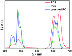
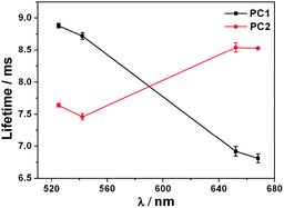
We are motivated to disclose the effects of the stop band on the optical properties of the guest NaYF4:Yb,Er nanoparticles. For this purpose, the choice of reference is of fundamental importance. The best way to study the effect of the PBG is to mismatch the PBG and the NaYF4:Yb,Er nanoparticles, by growing the inverse opal from PS colloidal spheres of a different size. Therefore, the reference sample PC2 was grown from 807 nm PS colloidal spheres (ESI,† Fig. S3) and the PBG position was around 836 nm (ESI,† Fig. S4). Since the PBG of PC2 resides out of the range of both the red and green emission bands of the NaYF4:Yb,Er nanoparticles, the UC luminescence spectra of PC2 is unaffected by the 3D ordered structure, and it shows a more intense green emission compared to the red one (Fig. 3). Thus, it is reasonable to deduce that the photonic crystal effects are responsible for the difference in the optical properties of the PC1 and PC2 samples, since the two samples were fabricated under the same conditions and with similar 3D ordered structures. To further confirm the influence of the PBG of the materials on the UC photoluminescence properties, the as-prepared PC1 sample was directly ground to destroy the regular 3D ordered structure, and this was confirmed by the SEM image (ESI,† Fig. S5). The emission spectra of the original and crushed PC1 samples are shown in Fig. 3. The green emission intensity is recovered when the framework was crumbled, which further confirms that the suppression of the green emission of the guest NaYF4:Yb,Er nanoparticles was attributable to the influence of Bragg diffraction in the PC1 sample. The behaviour of the lifetimes of the PC1 and PC2 samples at different wavelengths is presented in Fig. 4, which unambiguously shows lengthening within the range of the PBG. Owing to the complex behavior of the lifetimes, which can be explained by the different quenching constants of Er3+ depending on their locations, the PC1 and PC2 samples were fabricated under the same conditions. Therefore, the non-radiative contributions were the same for all samples, and the lifetime changes were a result of the changes in the radiative lifetime. According to theoretical calculations that have been done for perfect photonic crystals with high dielectric contrast,17 the formation of a PBG changes the density of states, and as the density of states increases, the lifetime becomes shorter. Since the green emission of the guest NaYF4:Yb,Er nanoparticles is in the PBG range for PC1, this spontaneous decay is inhibited, which leads to the increase of the corresponding luminescence lifetime. In contrast, the photonic stop band of the reference sample PC2 is out of the green emission wavelength, so the lifetime decreased. Photonic crystals have been demonstrated as an effective way of controlling the radiative lifetime.
 | ||
| Fig. 3 The emission spectra of the PC1 sample, reference PC2, and crushed PC1 sample. | ||
 | ||
| Fig. 4 Lifetimes of the PC1 and the reference sample PC2 at different wavelengths. | ||
In this work, a novel UC photonic crystal was fabricated as an air sphere SiO2 inverse opal embedded with NaYF4:Yb,Er nanoparticles. Furthermore, we successfully achieved the tuning of the UC optical properties of the NaYF4:Yb,Er nanoparticles by controlling the structure of the photonic crystal and the direction of measurement. It has been shown that the luminescence lifetime of the NaYF4:Yb,Er nanoparticles within this photonic crystal structure is altered. This increase of luminescence lifetime can be explained by the suppression effect of the PBG on the spontaneous emission of NaYF4:Yb,Er. This research not only realizes the colour modification of UC emission, but also opens the opportunity to control the propagation of photons.
This work was supported by NSFC (20671005, 20821091, and 20731160001) and MOST of China (2006CB601104). We thank Dr Bi-Wang Jiang for providing the PS microspheres.
Notes and references
- G. E. Moore, Electronics, 1965, 38, 114 Search PubMed.
- P. S. Peercy, Nature, 2000, 406, 1023 CrossRef CAS.
- A. I. Kingon, J.-P. Maria and S. K. Streiffer, Nature, 2000, 406, 1032 CrossRef CAS.
- E. Yablonovitch, Nat. Mater., 2003, 2, 648 CrossRef CAS.
- E. Yablonovitch, Phys. Rev. Lett., 1987, 58, 2059 CrossRef CAS.
- S. John, Phys. Rev. Lett., 1987, 58, 2486 CrossRef CAS.
- S. G. Romanov, A. V. Fokin and R. M. De La Rue, Appl. Phys. Lett., 1999, 74, 1821 CrossRef CAS; S. Y. Lin, J. G. Fleming, D. L. Hetherington, B. K. Smith, R. Biswas, K. M. Ho, M. M. Sigalas, W. Zubrzycki, S. R. Kurtz and J. Bur, Nature, 1998, 394, 251 CrossRef CAS; J. D. Joannopoulos, P. R. Villeneuve and S. H. Fan, Nature, 1997, 386, 143 CrossRef; Y. Z. Li, T. Kunitake, S. Fujikawa and K. Ozasa, Langmuir, 2007, 23, 9109 CrossRef CAS.
- I. S. Nikolaev, P. Lodahl and W. L. Vos, J. Phys. Chem. C, 2008, 112, 7250 CrossRef CAS; E. P. Petrov, V. N. Bogomolov, I. I. Kalosha and S. V. Gaponenko, Phys. Rev. Lett., 1998, 81, 77 CrossRef CAS.
- P. Lodahl, A. F. van Driel, I. S. Nikolaev, A. Irman, K. Overgaag, D. L. Vanmaekelbergh and W. L. Vos, Nature, 2004, 430, 654 CrossRef CAS.
- M. Aloshyna, S. Sivakumar, M. Venkataramanan, A. G. Brolo and F. C. J. M. van Veggel, J. Phys. Chem. C, 2007, 111, 4047 CrossRef CAS; E. Bovero and F. C. J. M. van Veggel, J. Am. Chem. Soc., 2008, 130, 15374 CrossRef CAS; X. Qu, H. Song, G. Pan, X. Bai, B. Dong, H. Zhao, Q. Dai, H. Zhang, R. Qin and S. Lu, J. Phys. Chem. C, 2009, 113, 5906 CrossRef CAS; S. G. Romanov, A. V. Fokin and R. M. De La Rue, Appl. Phys. Lett., 2000, 76, 1656 CrossRef CAS.
- J. C. Boyer, F. Vetrone, L. A. Cuccia and J. A. Capobianco, J. Am. Chem. Soc., 2006, 128, 7444 CrossRef CAS; J. C. Boyer, L. A. Cuccia and J. A. Capobianco, Nano Lett., 2007, 7, 847 CrossRef CAS; F. Auzel, Chem. Rev., 2004, 104, 139 CrossRef CAS; E. Downing, L. Hesselink, J. Ralston and R. Macfarlane, Science, 1996, 273, 1185 CrossRef CAS; R. Scheps, Prog. Quantum Electron., 1996, 20, 271 CrossRef CAS; J. F. Suyver, A. Aebischer, D. Biner, P. Gerner, J. Grimm, S. Heer, K. W. Kramer, C. Reinhard and H. U. Gudel, Opt. Mater., 2005, 27, 1111 CrossRef CAS; N. Menyuk, K. Dwight and J. W. Pierce, Appl. Phys. Lett., 1972, 21, 159 CAS; K. W. Krämer, D. Biner, G. Frei, H. U. Güdel, M. P. Hehlen and S. R. Lüthi, Chem. Mater., 2004, 16, 1244 CrossRef; H. X. Mai, Y. W. Zhang, L. D. Sun and C. H. Yan, J. Phys. Chem. C, 2007, 111, 13721 CrossRef CAS; F. Zhang, Y. Wan, T. Yu, F. Q. Zhang, Y. F. Shi, S. H. Xie, Y. G. Li, L. Xu, B. Tu and D. Y. Zhao, Angew. Chem., Int. Ed., 2007, 46, 7976 CrossRef CAS; F. Zhang and D. Y. Zhao, ACS Nano, 2009, 3, 159 CrossRef CAS.
- M. Fujita, S. Takahashi, Y. Tanaka, T. Asano and S. Noda, Science, 2005, 308, 1296 CrossRef CAS.
- C. López, Adv. Mater., 2003, 15, 1679 CrossRef CAS.
- S. G. Romanov, T. Maka, C. M. S. Torres, M. Muller, R. Zentel, D. Cassagne, J. Manzanares-Martinez and C. Jouanin, Phys. Rev. E, 2001, 63, 056603 CrossRef CAS.
- R. C. Schroden, M. Al-Daous, C. F. Blanford and A. Stein, Chem. Mater., 2002, 14, 3305 CrossRef CAS.
- S. Heer, K. Kömpe, H. U. Güdel and M. Haase, Adv. Mater., 2004, 16, 2102 CrossRef CAS; J. H. Zeng, J. Su, Z. H. Li, R. X. Yan and Y. D. Li, Adv. Mater., 2005, 17, 2119 CrossRef CAS.
- R. Sprik, B. A. van Tiggelen and A. Lagendijk, Europhys. Lett., 1996, 35, 265 CrossRef CAS; N. Vats, S. John and K. Busch, Phys. Rev. A, 2002, 65, 043808 CrossRef; K. Busch and S. John, Phys. Rev. E, 1998, 58, 3896 Search PubMed.
Footnote |
| † Electronic supplementary information (ESI) available: Detailed synthesis procedures and additional experimental results. See DOI: 10.1039/b911734b |
| This journal is © The Royal Society of Chemistry 2009 |
