Magnetic field assisted nanoparticle dispersion†
Bernard
Stuyven
a,
Qinghua
Chen
b,
Wim Van de
Moortel
c,
Heiko
Lipkens
a,
Bart
Caerts
c,
Alexander
Aerts
a,
Lars
Giebeler
a,
Bernard Van
Eerdenbrugh
d,
Patrick
Augustijns
d,
Guy Van den
Mooter
d,
Jan Van
Humbeeck
e,
Johan
Vanacken
b,
Victor V.
Moshchalkov
b,
Jan
Vermant
c and
Johan A.
Martens
*a
aCentre for Surface Chemistry and Catalysis, Department M2S, Catholic University of Leuven, 3001, Heverlee, Belgium. E-mail: johan.martens@biw.kuleuven.be; Fax: +32 16 321998; Tel: +32 16 321610
bINPAC-Institute for Nanoscale Physics and Chemistry, Catholic University of Leuven, 3001, Heverlee, Belgium
cDepartment of Chemical Engineering, Catholic University of Leuven, 3001, Heverlee, Belgium
dLaboratory for Pharmacotechnology and Biopharmacy, Catholic University of Leuven, 3001, Heverlee, Belgium
ePhysical Metallurgy and Materials Engineering, Catholic University of Leuven, 3001, Heverlee, Belgium
First published on 30th October 2008
Abstract
Magnetohydrodynamic nanoparticle dispersion is an energy efficient method to deaggregate nanoparticles, combining hydrodynamic forces of turbulent flow with Lorentz forces generated by a magnetic field.
New practical applications of the magnetic force are reported on a regular basis. Spectacular examples are levitating trains, as operational in Shanghai1 and the magnetic confinement of hot plasma in the ITER project.2 In the fight against cancer, biocompatible magnetic nanoparticles are injected into the tumor and heated with an external alternating magnetic field to create local hyperthermia.3 Ferrofluids are applied in many areas such as automotives, aerospace, medicine, electronics, mechanical engineering and optics.4
In the area of fluid hydrodynamics the presence of a magnetic field, even of moderate strength, has been known to alter the laminar flow profile of a conducting solvent and to enhance the velocity gradients and shear rates near the walls of the channel.5 This magnetohydrodynamic effect was thought to be responsible for an enhanced flocculation rate of suspensions of cholesterol and polystyrene particles in aqueous sodium chloride solution circulated through an orthogonal magnetic field.5 Magnetohydrodynamic forces and magnetization of particles induces attraction forces among particles and aggregation.5,6
Aggregation of nanoparticles is a general problem in nanotechnological production processes because it reduces the advantages associated with the large surface area of single particles.7–9 Aggregated particles are currently dispersed using microwaves,10 ultrasound,11 homogenization,12 media13,14 and jet milling .15 Here we report on the observation that a permanent magnetic field can assist the breakup of nanoparticleaggregates suspended in a turbulent liquid flow.
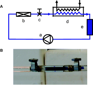
Experiments were first performed on model systems, prepared by aggregating a commercial Ludox®silicasol with 36 nm primary particle size aggregated using KNO3 solution to a size of 1400 nm, as measured by dynamic light scattering (see ESI† ). A volume of 3.5 L of silica suspension was circulated through an in-line dispersion setup, comprising a double membrane pump, temperature, flow and volume control (Fig. 1A). The dispersion device (ESI† ) consisted of a restriction in the flow field generating a turbulent flow regime at a Reynolds number of 26![[thin space (1/6-em)]](https://www.rsc.org/images/entities/char_2009.gif) 000. Block magnets could be externally mounted on the dispersing element to generate an orthogonal magnetic field of 0.31 T (Fig. 1B).
000. Block magnets could be externally mounted on the dispersing element to generate an orthogonal magnetic field of 0.31 T (Fig. 1B).
 | ||
| Fig. 1 (A) Experimental setup with (a) membrane pump, (b) dispersing device, (c) sampling valve, (d) heat exchanger and (e) piston-cylinder volume adaptation system. (B) Dispersing device with restriction (colored in blue) and a block magnet mounted on either side. | ||
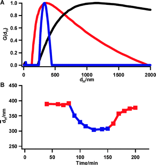
Circulation of the silica suspension through the dispersing device without magnets for 1 h already led to an aggregate size reduction to a mean value of 261 nm (red compared to black curve in Fig. 2A). With magnets mounted the aggregate size was smaller (mean value of 169 nm compared to 261 nm). Moreover, the particle size distribution in presence of the magnetic field was much narrower (Fig. 2A, blue compared to red curve). Additional experiments in the Reynolds numbers range 8000–37![[thin space (1/6-em)]](https://www.rsc.org/images/entities/char_2009.gif) 000 confirmed the beneficial influence of the magnetic field on particle size reduction as well as size distribution.
000 confirmed the beneficial influence of the magnetic field on particle size reduction as well as size distribution.
 | ||
Fig. 2 (A) Volume fraction distribution (G(dH)) of particle size (dH) of silicaaggregates before (black) and after treatment during 1 h with the dispersing device at Reynolds number of 26![[thin space (1/6-em)]](https://www.rsc.org/images/entities/char_2009.gif) 000 in presence (blue) and absence (red) of magnetic field. (B) Mean particle size of silicaaggregates during dispersing treatment at Reynolds number of 8000. Magnets are mounted after 80 min and removed after 150 min of treatment. 000 in presence (blue) and absence (red) of magnetic field. (B) Mean particle size of silicaaggregates during dispersing treatment at Reynolds number of 8000. Magnets are mounted after 80 min and removed after 150 min of treatment. | ||
In another experiment, an aggregated silica suspension with initial mean aggregate size of 1800 nm was circulated at a Reynolds number of 8000. The size evolution was monitored as a function of time (Fig. 2B). After the aggregate size stabilized around 390 nm in absence of magnetic field, the block magnets were mounted after 80 min without interrupting the flow. The aggregate size decreased to about 310 nm. Removal of the magnets after 150 min caused the particles to grow again, revealing the reversibility of the magnetic effect on aggregate size.
The potential of the magnetic dispersing device on technologically relevant systems was explored using an aqueous suspension of aggregated γ-alumina particles with a primary particle size of ca. 20 nm. The magnetic dispersing device was integrated in an experimental setup with a volume of 100 mL comprising a peristaltic pump and temperature control (ESI† ). Three separate experiments of 1 h were performed in the presence, and three control experiments in the absence of a magnetic field, in random order, each time with a freshly prepared suspension. The starting γ-alumina suspensions showed pronounced aggregation and sedimentation of micrometer size aggregates . Under turbulent flow conditions at a Reynolds number of 8000, there was a size reduction with respect to the original suspension and formation of particles in the submicrometer range (red curves in Fig. 3A). The average aggregate size could be reduced to about the half of the size by mounting permanent block magnets perpendicular to the constriction (blue curves in Fig. 3A). The size reduction of the γ-aluminaaggregates was not permanent as a precipitate formed upon storage of treated samples.
For obtaining the particle size reduction with the magnets, the magnitude of the Reynolds number proved to be critical. At the transition from the turbulent to the laminar regime (Re = 4000) the magnetic field hardly had an influence on particle size (Fig. 3B), while in the laminar regime (Re = 2000) bigger aggregates were even obtained with the magnets on (Fig. 3C). Clearly, laminar flow favors aggregation, confirming the earlier observation with cholesterol and polystyrene suspensions in a similar experimental setup.5
 | ||
| Fig. 3 Volume fraction distribution (G(dH)) of particle size (dH) of γ-aluminaaggregates treated during 1 h with the dispersing device at different Reynolds numbers (Re): (A) Re = 8000; (B) Re = 4000; (C) Re = 2000. Blue curves: experiments with magnets mounted; red curves: experiments without magnets. | ||
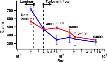
The particle size dependence on Reynolds number is summarized in Fig. 4. In presence of the magnetic field a minimum particle size of ca. 315 nm was reached at a Reynolds number of 8000. Without magnets, the Reynolds number had to be increased to over 21![[thin space (1/6-em)]](https://www.rsc.org/images/entities/char_2009.gif) 000 to generate a similar size (Fig. 4), which corresponds to a tenfold increase in energy consumption. At the highest Reynolds numbers investigated (up to 64
000 to generate a similar size (Fig. 4), which corresponds to a tenfold increase in energy consumption. At the highest Reynolds numbers investigated (up to 64![[thin space (1/6-em)]](https://www.rsc.org/images/entities/char_2009.gif) 000), the final particle sizes with and without magnets converged to a same value (Fig. 4). The hydrodynamic particle diameter obtained using the dispersing device of 315 nm is still larger than the elementary particles of this γ-alumina material measuring 20 nm. The circulation system comprising the dispersing device was mounted in a synchrotron SAXS setup (ESI† ). The SAXS patterns of a parent γ-alumina suspension and magnetically treated suspensions were indistinguishable, revealing that particles smaller than 150 nm were not formed (ESI† ).
000), the final particle sizes with and without magnets converged to a same value (Fig. 4). The hydrodynamic particle diameter obtained using the dispersing device of 315 nm is still larger than the elementary particles of this γ-alumina material measuring 20 nm. The circulation system comprising the dispersing device was mounted in a synchrotron SAXS setup (ESI† ). The SAXS patterns of a parent γ-alumina suspension and magnetically treated suspensions were indistinguishable, revealing that particles smaller than 150 nm were not formed (ESI† ).
 | ||
Fig. 4 Average particle size over three experiments of γ-aluminaaggregates treated during 1 h with the dispersing device at Reynolds numbers (Re) in the range 2000–64![[thin space (1/6-em)]](https://www.rsc.org/images/entities/char_2009.gif) 000. Blue curves: experiments with magnets mounted; red curves: experiments without magnets. 000. Blue curves: experiments with magnets mounted; red curves: experiments without magnets. | ||
The stability of a suspension of charged particles can be described as a dynamic equilibrium between attractive forces (mainly van der Waals ) and repulsive forces (predominantly electrostatic). Under laminar flow conditions velocity gradients enhance the collision frequency as well as the hydrodynamic shear stress. A dynamic equilibrium between aggregate growth and breakup defines the aggregate size.
Under turbulent conditions strong velocity gradients exist near the channel walls. Additionally aggregates are subjected to random turbulent stress fluctuations on opposite sides, which cause their rotation about a vorticity axis. The resulting varying oscillatory stress on the aggregates may lead to deformation and rupture.16 As growth and breakup are in dynamic balance, the particles reach a steady state size which depends on the flow strength.
A transverse magnetic field complicates the force balance as it introduces Lorentz forces. With the diamagnetic silica and alumina particles of this study, attraction by magnetization can be neglected. Under laminar flow conditions a magnetic field drags charged particles to the channel wall where local velocity gradients increase collision frequency as well as shear stress. The observed alumina particle growth under laminar flow conditions (Fig. 3C, Re = 2000) suggests the collision enhancement to dominate. Under turbulent regime the shear stresses at the wall increase causing deformation of the aggregates . Additionally the stress fluctuations are amplified by the Lorentz force acting in opposite directions on opposite sites of a rotating charged aggregate .
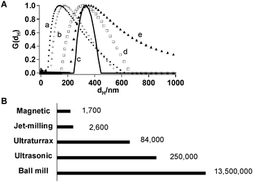
The new magnetic field assisted dispersion technique was compared to the present day techniques, including planetary ball milling , ultrasonic and ultraturrax techniques and jet-milling with respect to particle size and energy efficiency in the treatment of silica suspension (Fig. 5). Ultrasonic and ultraturrax treatment produced the smallest particle size. Particle size obtained with jet milling and magnetic treatment were similar, while the particles tended to be larger when processed in the planetary ball mill (Fig. 5A). The magnetic field assisted dispersion technique produced the most uniform particle size (Fig. 5A). After ultrasonic and ultraturrax treatment and ball milling , the particle size distribution presented significant tailing. An estimation of energy consumption puts the magnetic technique ahead of the other technologies (Fig. 5B).
 | ||
Fig. 5 (A) Volume fraction distribution (G(dH)) of particle size (dH) of silicaaggregates after treatment with ultrasonic device (a, ●), ultraturrax (b, +), magnetic dispersing device at Re = 26![[thin space (1/6-em)]](https://www.rsc.org/images/entities/char_2009.gif) 000 (c, —), jet-milling at Re = 25 000 (c, —), jet-milling at Re = 25![[thin space (1/6-em)]](https://www.rsc.org/images/entities/char_2009.gif) 000 (d, □) and planetary ball mill (e, ▲). (B) Energy consumption in J L−1 of the different dispersion techniques (ESI† ). 000 (d, □) and planetary ball mill (e, ▲). (B) Energy consumption in J L−1 of the different dispersion techniques (ESI† ). | ||
In conclusion, we have demonstrated the effect of a stationary magnetic field on aggregate size in flowing silica and alumina suspensions. Reproducible results showed that a magnetic field, especially under turbulent flow conditions at intermediate Reynolds numbers, can be an efficient aid to disperse nanoparticles and intensify the dispersion process. Our new method potentially can be applied in many areas. It could possibly aid the dispersion of functional nanoparticles in polymeric melts. Dispersion of minerals as well as organic pigments in concrete, polymers, paints and coatings could be enhanced. Magnetic treatment shows great potential in the fabrication of personal care products, e.g. for enhancing the activity of sun blockers and incorporation of pigment particles in cosmetics. It could be applicable in compound particle dispersion into pharmaceutical formulations. Further examples are to be found in the synthesis of nanocomposite materials, display coatings, electronic coatings, imaging technology and contrast agents and for dispersing optically active materials exhibiting plasmon resonance phenomena.
This work was sponsored by K. U. Leuven Interdisciplinary research programme. W. Bras and K. Kvashnina (DUBBLE) assisted with SAXS. T. Caremans made the TOC figure.
Notes and references
- R. Goodall, Phys. Technol., 1985, 16, 207 Search PubMed.
- http://www.iter.org .
- U. Gneveckow, A. Jordan and R. Scholz, Med. Phys., 2004, 31, 1444 CrossRef.
- S. A. Safran, Nat. Mater., 2003, 2, 71 CrossRef CAS.
- R. P. A. R. Van Kleef, H. W. Myron, P. Wyder and M. R. Parker, J. Appl. Phys., 1983, 54, 4223 CrossRef CAS.
- K. W. Busch, S. Gopalakrishnan, M. A. Busch and E. Tombácz, J. Colloid Interface Sci., 1996, 183, 528 CrossRef CAS.
- B. E. Rabinow, Nat. Rev. Drug Discovery, 2004, 3, 785 CrossRef CAS.
- J. Tollefson, Nature, 2007, 450, 334 CrossRef CAS.
- J. R. Capadona, O. Van Den Berg, L. A. Capadona, M. Schroeter, S. J. Rowan, D. J. Tyler and C. Weder, Nat. Nanotechnol., 2007, 2, 765 Search PubMed.
- Z. An, W. Tang, C. J. Hawker and G. D. Stucky, J. Am. Chem. Soc., 2006, 128, 15054 CrossRef CAS.
- M. Pohl, S. Hogekamp, N. Q. Hoffmann and H. P. Schuchmann, Chem.-Ing.-Tech., 2004, 76, 392 CrossRef CAS.
- W. D. Pandolfe, J. Dairy Sci., 1982, 65, 2035.
- A. Kwade, Powder Technol., 1999, 105, 14 CrossRef CAS.
- S. Mende, F. Stenger, W. Peukert and J. Schwedes, Powder Technol., 2003, 132, 64 CAS.
- M. Mebtoul, J. F. Large and P. Guigon, Int. J. Miner. Process., 1996, 44–45, 77 CrossRef CAS.
- D. G. Thomas, AIChE J., 1964, 10, 517 CrossRef CAS.
Footnote |
| † Electronic supplementary information (ESI) available: Details of silica and alumina suspensions, dispersing devices, DLS data interpretation, dispersion techniques and estimation of energy consumption. See DOI: 10.1039/b816171b |
| This journal is © The Royal Society of Chemistry 2009 |
