Solar water-splitting into H2 and O2: design principles of photosystem II and hydrogenases
Wolfgang Lubitz*, Edward J. Reijerse and Johannes Messinger†*
Max Planck Institut für Bioanorganische Chemie, Stiftstrasse 34-36, 45470, Mülheim, Ruhr, Germany. Fax: +49 208 306 3955; Tel: +49 208 3063614E-mail: lubitz@mpi-muelheim.mpg.de
First published on 30th June 2008
Abstract
This review aims at presenting the principles of water-oxidation in photosystem II and of hydrogen production by the two major classes of hydrogenases in order to facilitate application for the design of artificial catalysts for solar fuel production.
 W. Lubitz | W. Lubitz is director of the MPI for Bioinorganic Chemistry and a specialist in advanced EPR techniques. He has a strong interest in both water-splitting and hydrogen production. |
 E. Reijerse | E. Reijerse is working on hydrogenases using FTIR and EPR/ENDOR spectroscopies. |
 J. Messinger | J. Messinger is analyzing photosynthetic and artificial water-splitting employing O2 measurements, mass spectrometry (MIMS), EPR and XAS. |
1. Introduction
Practically all life on earth depends directly or indirectly on photosynthesis. This therefore arguably most important chemical process on our planet1–3 stores the sun's energy in chemical compounds (carbohydrates). The products of photosynthesis are the only renewable source of food. Photosynthesis also created our oxygen-rich atmosphere by water oxidation and thereby laid the basis for the formation of the protective ozone layer in the stratosphere. These events enabled the development of higher life on earth. Furthermore, all fossil fuels – oil, coal and natural gas – have been created from products of photosynthesis over the last 2.5 billion years. The rash and unsolicitous exploitation of these valuable resources during the past 1 to 2 centuries led to an enormous increase of energy usage in our society, which is still increasing in spite of the limited resources.4 The burning of carbon-rich fuels also led to a significant rise of carbon dioxide (CO2) levels in the atmosphere, a greenhouse gas that contributes to the global climate change with many adverse effects on our planet and human life.5The economical and socio-political consequences of the shortage of fossil fuels are already felt today. With the increase of world population and economic growth the global energy demand will continue to increase in the coming decades. Thus, it is high time to find alternative, sustainable energy resources. An obvious idea is to exploit the abundant energy of the sun: the energy hitting the surface of the earth by far exceeds human needs.6 Solar energy has an enormous potential as clean, abundant and economical energy source, but must first be captured and converted into useful forms of energy. This includes conversion into heat, electricity and (chemical) fuels. In particular the efficient production of a clean, storable “solar fuel” would represent a very important breakthrough in scientific research.7 Such a fuel must be formed from abundant, inexpensive materials such as water, which could be split into molecular oxygen and molecular hydrogen. Hydrogen is often considered to be the ideal fuel of the future since its combustion generates only water. The problems of H2 generation, storage and transport have been intensively discussed in recent years.8–11
A promising way for light-driven water splitting would be to mimic the molecular and supramolecular organization of the natural photosynthetic system, i.e. “artificial photosynthesis”.12,13 However, many obstacles must be overcome. One of the major difficulties is the coupling of the light-induced (one-photon) one-electron charge separation to the multi-electron catalytic processes leading to water oxidation and fuel production. Another problem is the sensitivity and the limited lifetime of isolated native enzymes and current artificial devices.
Light-induced water-splitting and release of oxygen and protons is performed in nature in oxygenic photosynthesis by green plants, algae and cyanobacteria. The responsible highly complex enzyme is called photosystem (PS) II.14 Many green algae and cyanobacteria also contain an enzyme that can convert the released protons into dihydrogen. This enzyme is called hydrogenase.15,16 The process is depicted in Fig. 1, together with a view of the respective protein complexes17,18 and a possible scheme mimicking the natural process in vitro.19
![Light induced water splitting by photosystem II in photosynthesis and hydrogen production by an [FeFe] hydrogenase shown together with the structure of respective protein complexes17,18 and a possible scheme19 for mimicking the natural process.](/image/article/2008/EE/b808792j/b808792j-f1.gif) | ||
| Fig. 1 Light induced water splitting by photosystem II in photosynthesis and hydrogen production by an [FeFe] hydrogenase shown together with the structure of respective protein complexes17,18 and a possible scheme19 for mimicking the natural process. | ||
Photosystem II and several hydrogenases have been crystallized and structurally analyzed by X-ray crystallography17,18 in recent years. The active sites contain complex multinuclear transition metal clusters that have been the subject of intense spectroscopic investigations aiming at a detailed understanding of their structure and function. Slowly a mechanistic understanding of these important processes is developing.
Knowledge of the basic principles of water oxidation and hydrogen conversion in nature is a goal of major importance both for basic research and possible application in our society. This would allow us to use the organisms – or the isolated enzymes – in biotechnological processes.20–23 Furthermore, it would provide the foundation for designing biomimetic – or bioinspired – artificial catalysts for large-scale water splitting and hydrogen production in the future.
2. Water oxidation
Oxygenic photosynthesis was ‘invented’ on earth about 2.5 billion years ago at the level of cyanobacteria24,25 and resulted in an enormous evolutionary advantage for these organisms since it allowed them to exploit the nearly unlimited electron source water. It is therefore surprising that evolution has, in contrast to for example hydrogenases (see below), created only one unique catalyst capable of performing light-induced water-splitting, which is known as photosystem II (PSII). It is also remarkable that so far only very minor differences have been found on the level of the water-splitting complex between different organisms such as higher plants, green algae and cyanobacteria. This uniqueness underpins the high level of complexity that is required to perform this strongly oxidizing reaction within a protein matrix. Although not all facets are yet known, several important features of the water-splitting reaction in PSII have been unraveled due to intense research efforts by many groups in the field (for recent reviews see26–34). These key features will be briefly outlined below, and their possible significance for constructing artificial catalysts for the water-splitting half-reaction (1) is discussed.| 2H2O → O2 + 4H+ + 4e− | (1) |
2.1 Photosystem II
Photosystem II is an integral part of the thylakoid membrane. In the thermophilic cyanobacterium Thermosynechococcus (T.) elongatus it consist of about 20 protein subunits that harbor 77 cofactors: 35 Chla; 14 lipids (+ 3 detergent molecules); 11 β-carotenes; 2 plastoquinones, PQ; 2 pheophytines, Pheo; 1 Mn4OxCa complex, 2 haem Fe; 1 non-haem Fe; 1 hydrogencarbonate, HCO3−.18,35 In addition Cl− is a known cofactor of water-splitting,36,37 but was not yet identified in crystal structures. The overall reaction of PSII is that of a light-driven water: plastoquinone oxidoreductase: | (2) |
PSII utilizes visible light (∼400–700 nm) to drive this reaction, which contributes significantly to the build-up of a proton gradient across the thylakoid membrane. This pH difference is employed by the ATPase to drive the synthesis of ATP from ADP and Pi.
The reactions occurring in PSII can be divided into four processes:
| ChlA + hν → ChlA*. | (3a) |
The inner PSII antenna is formed by CP43 and CP47 (Fig. 2A). The captured light energy is then transferred to the reaction center (see below) by exciton transfer according to:38
| ChlA* ChlA → ChlA ChlA*. | (3b) |
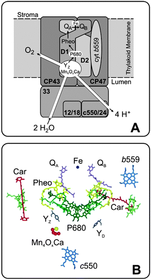 | ||
| Fig. 2 Simplified scheme of the core components of the water-splitting photosystem II complex that is embedded into the thylakoid membrane of chloroplasts or cyanobacteria (A); adapted from Hillier.28 Only the relative positioning of the five most important transmembrane subunits and of three extrinsic proteins are shown (the full complex consists of about 20 subunits). The two central subunits are the D1 and D2 proteins. They bind all the electron transfer components. A detailed view of the electron transfer cofactors is given in panel B on the basis of the 3.0 Å crystal structure.18 In cyanobacteria, cytochrome c550 is part of one of the extrinsic proteins, but has no known function in water-splitting. | ||
| ChlA* ChlRC Pheo → ChlA ChlRC* Pheo → ChlA ChlRC˙+ Pheo˙−. | (4) |
The radical cation ChlRC˙+, also known by the absorption maximum of ChlRC as P680˙+, has an estimated oxidizing potential of +1.2 to 1.3 V, the highest known in biology.40 PSII therefore requires protection, for example against oxidation or long lived triplet states, 3Chl, that can form by charge recombination reactions. The two carotenoid molecules, Car, (Fig. 2B) and the cyt b559 (Fig. 2A and B) are believed to be involved in this defense system. The primary charge separation is stabilized by electron transfer from Pheo˙− to the bound plastoquinone (PQ) molecule QA, and by the reduction of P680˙+ by a redox active tyrosine side chain of the D1 protein, YZ. These electron transfer reactions increase the distance between the charged species and decrease the energy difference ΔG. Both factors (together with the subsequent reactions described below) significantly minimize competing recombination reactions, leading to an excellent quantum efficiency of PSII for water-splitting (over 90%),41,42 but to a less favorable energy efficiency.43,44
| QA˙− QB → QA QB˙− | (5a) |
| QA˙− QB˙− + 2H+stroma → QA QBH2 | (5b) |
| QA QBH2 + PQ → QA QB + PQH2 | (5c) |
| PQH2 + cytb6fox → PQ + cytb6fred + 2H+lumen | (5d) |
The reactions (5a)–(5c) constitute the two-electron gate of the acceptor side of PSII. They further stabilize the charge separation by ensuring that the electrons are transported away from PSII via the photosynthetic electron transport chain that finally leads to the reduction of CO2 to carbohydrates. Reactions (5) also couple the electron transport with a proton translocation that is required for ATP synthesis (see above). The non-heme iron between QA and QB (Fig. 2) appears to serve mostly a structural role, but it also binds a hydrogencarbonate ion that maybe involved in the protonation of QB2−.
2.2 Geometric structure of the WOC
Several crystal structures of PSII isolated from the thermophilic cyanobacteria T. elongatus or T. vulcanus were obtained.18,35,48 Currently the best resolution is 3.0 Å.18 While these structures give invaluable insight into the overall arrangement of most cofactors and the arrangement of the different protein subunits, the ‘pictures’ obtained for the Mn4OxCa cluster are rather fuzzy and vary between structures. The reasons for that are (1) the too low resolution (Mn–Mn distances are of the order of 2.7 Å, see below) and (2) the fast reduction of the Mn4OxCa cluster that is accompanied by the loss of its structure due to radiation damage caused by radicals that are created by the required intense X-ray beams.49 Nevertheless, the crystal structures provide an approximate overall shape of the cluster, and also affirm the binding place of Ca next to Mn as previously suggested by EXAFS spectroscopy.50–52 A breakthrough was recently achieved by combining crystallography and EXAFS measurements. This approach allowed collecting polarized XANES and EXAFS spectra along the three crystallographic axes of PSII single crystals. In this way the large number of previously proposed models for the cluster could be reduced to four very similar models, that all have the same Mn4 core and differ only in the relative position of Ca and/or the orientation of the Mn4 unit.47 One of these structures is shown in Fig. 3 together with a ligand environment that is taken from the crystal structure. The precise bridging motif between Mn and Ca could not be derived and is therefore not shown. It has to be noted that without adjustments the amino acids around the Mn4OxCa cluster are not in optimal positions for ligands. This is most likely a consequence of the radiation damage during the crystallographic measurements. Therefore efforts are under way employing QM/MM and DFT calculations to obtain more realistic overall models of the WOC.53–56 These calculations also take into account further known components of the WOC that were not yet detected by crystallography or EXAFS. These components are the two substrate water molecules (see below) and chloride, Cl−. While one recent spectroscopic study suggest that Cl− may not be a direct ligand of manganese,57 functional studies indicate that it has to be at least in the vicinity of the Mn4OxCa cluster.36 Hydrogencarbonate (bicarbonate), which is important during the photo-assembly of the Mn4OxCa cluster,58 was recently proven not to be a tightly bound constituent of the functional complex.59–61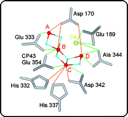 | ||
| Fig. 3 Structural model (one out of four possible) of the Mn4OxCa cluster derived from polarized EXAFS spectroscopy on photosystem II single crystals:47 Mn (red), oxygen (blue) and Ca (yellow). The model is placed in the EXAFS-derived orientation within the protein ligands determined by crystallography18 without any optimization. Green lines indicate distances smaller than 3 Å, while orange lines signify distances longer than 3 Å. | ||
Previous EXAFS experiments on frozen PSII-suspensions that were trapped in different Si states also demonstrate that the Mn4OxCa cluster undergoes structural changes during the catalytic cycle62–64 (see below and Fig. 6). Therefore it is important to note that the structure of the Mn4OxCa cluster in the S1 state (Fig. 3) is, to a yet not fully determined extend, different from that in the S3 and/or the S4 states in which the O–O bond is formed.
2.3 Function of the WOC
The Mn4OxCa cluster is the ‘heart’ of the WOC and it fulfils, together with the protein matrix, several vital functions that are outlined in the following.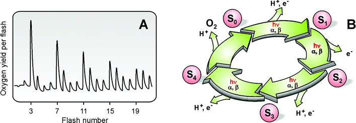 | ||
| Fig. 4 Flash-induced oxygen evolution pattern (FIOP) of spinach thylakoids measured at 10 °C (Panel A). The period-four oscillation in oxygen-evolution is explained by the Kok-model65 displayed in Panel B. The different states of the Mn4OxCa cluster that are attained after various numbers of light flashes (hν) are termed Si states, where i = 0, …, 4 indicates the number of oxidizing equivalents stored in the cluster. The damping of the FIOP is explained by the miss (α) and double hit (β) parameters. | ||
Due to the required high-oxidative power, and the potential formation of harmful side products such as superoxide radicals or peroxides, the lifetime of the WOC and its surrounding D1 protein is limited to less than 30 min in sun light. On the basis of the best known in vitro O2-evolution72 rates of about 6000 μmol O2 mg−1 Chl h−1 (with 35 Chl per reaction center this is equal to a turnover time of 17 ms per released O2 molecule, which is possibly limited by electron transfer to an artificial acceptor) this corresponds to a total turnover number of about 100 000 O2 per WOC, while by employing the 1–2 ms O2 release time an upper estimate of about 1 million turnovers within the life time of a WOC is reached. As will be discussed below most, if not all of the few presently available artificial water-splitting complexes suffer, in a much more severe way, from the same problem. Photosynthetic organisms have devised an efficient repair mechanism to solve this problem. By this mechanism the most damage sensitive part, the D1 protein, is selectively exchanged against a newly synthesized replacement protein. Then the Mn4OxCa cluster is reassembled via a light-driven process known as photo-activation.73
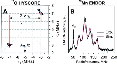 | ||
| Fig. 5 X-Band 17O HYSCORE (A) and Q-band 55Mn ENDOR (B) spectra of the WOC in the S2 state spinach PSII membranes. The data were obtained at 4.2 K. For further details see text and refs. 80–82. Reprinted with permission from ref. 80 (A) and 82 (B). Copyright (2007/2008) American Chemical Society. | ||
Such experiments and their detailed analysis will hopefully allow us in the future to better localize the substrate binding sites. One current suggestion82 for a binding scenario for the two substrate water molecules in the S0, S1 and S2 states is presented in the bottom row of Fig. 6 (the small black spheres labeled Ws and Wf represent the suggested positions of the oxygens of the slow and fast exchanging substrate water molecules, respectively).
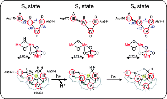 | ||
| Fig. 6 Schemes of the electronic (top row) and geometric (middle row) structures of the Mn4 unit within the Mn4OxCa cluster as derived from 55Mn-ENDOR81,82 and EXAFS47,62,83 spectroscopies in the S0, S1 and S2 states of the water-oxidizing complex of photosystem II. The exchange coupling strength (cm−1) is given in blue numbers and is also symbolized by double lines (strong), single lines (medium strength) and dashed lines (weak) antiferromagnetic coupling. The bottom row shows a possible interpretation of the currently available experimental data on these states, which also includes suggestions for the binding sites of the slowly (Ws) and fast (Wf) exchanging substrate water molecules (small black spheres). Red circles signify Mn ions, bold red circles indicate the Mn ion suggested to be oxidized during the transition. Blue spheres symbolize bridging oxygens. Bridging carboxylate side chains are depicted in grey. Adapted from ref. 82. | ||
2.4 Electronic structure of the Mn4OxCa complex
Detailed information about the electronic structure of the Mn4OxCa cluster is key to understanding the mechanism of (water oxidation) in the WOC (see e.g.refs. 55 and 82). Since in each step of the Kok cycle (Fig. 4B) one electron is pulled out of the Mn4OxCa cluster (Fig. 3) every second state should be paramagnetic. Indeed cw-EPR signals are known for the S284 and S0 states.85–87 In principle these spectra contain all the required information about these two states, but the number of fitting parameters is too large for obtaining conclusive answers. Therefore, recently 55Mn-ENDOR spectroscopy was employed at X-band (S2 state,88) and Q-band (S2 and S0;81,82) frequencies (Fig. 5(B)). The Q-band studies demonstrated that the S0 and S2 states have the overall oxidation states Mn4(III,III,III,IV) and Mn4(III,IV,IV,IV), respectively. By also taking information from other spectroscopic measurements into account a tentative assignment of the individual Mn-oxidation states and the exchange coupling constants shown in Fig. 6 (top row) was derived. This also allowed for the first time a specific description of the already known structural change during the S0 → S1 transition62,64 to a contraction of the MnA–MnB distance due to the oxidation of one Mn(III) to Mn(IV), which is coupled to a deprotonation of a μ-OH bridge (top two rows in Fig. 682). Together with additional information, for example about the structure and substrate water binding (see above), the tentative reaction scheme for the S0 → S1 → S2 transitions shown in the lower row of Fig. 6 can be suggested.Other suitable techniques for assessing the Mn oxidation states are XANES (X-ray absorption near edge spectroscopy,64,89 Kβ-fluorescence spectroscopy89 and RIXS (resonant inelastic X-ray scattering) spectroscopy.90 These techniques can probe all Si states, but the interpretation is also not straightforward, in part due to the lack of suitable theory, in part owing to structural changes between the Si states that complicate the analysis. While it is now clear that there are Mn(III) to Mn(IV) oxidations during the S0 → S1 and S1 → S2 transitions, it currently remains a matter of controversy whether a similar oxidation happens during the S2 → S3 transition, or whether in this transition a ligand centred oxidation occurs. Similarly the nature of the structural rearrangement between S2 and S3 is hotly debated: Dau and co-workers suggest the formation of one additional μ-oxo bridge and thereby the formation of one more short Mn–Mn distance.64 In contrast, Yachandra and co-workers observe a lengthening of several Mn–Mn distances by 0.1–0.3 Å, which is suggestive of a μ-oxo bridge oxidation within the cluster.63 Clarification of this controversy will be of utmost importance for understanding the mechanism of photosynthetic water-splitting.
2.5 Suggested mechanisms of O–O bond formation
There is a large number of proposed mechanisms for O–O bond formation in PSII. These have been extensively reviewed in several recent articles.28,30,33,91 Here only the principles of the currently most favored mechanisms will be briefly summarized.![[double bond, length as m-dash]](https://www.rsc.org/images/entities/char_e001.gif) O would be formed, which may also be formulated as Mn(V)
O would be formed, which may also be formulated as Mn(V)![[triple bond, length as m-dash]](https://www.rsc.org/images/entities/char_e002.gif) O+ or Mn(IV)–O˙. Alternatively, a μ2- or μ3-oxo bridge may act as electrophile (not shown). The electrophile is attacked by a nucleophilic water molecule. This may either be a bulk water molecule, or a water/hydroxo bound to Ca or bridging between Ca and Mn (Fig. 7, top row). Since the water-exchange experiments demonstrate binding of both substrate molecules in the S3 state, the attack of a free water molecule appears highly unlikely. These type of mechanisms require a Mn(III)→Mn(IV) oxidation during the S2 → S3 transition and another oxidation of the Mn4OxCa cluster during the S3 → S4 transition. The latter oxidation is either assumed to be a Mn(IV) → Mn(V) oxidation or a ligand (substrate) based oxidation.
O+ or Mn(IV)–O˙. Alternatively, a μ2- or μ3-oxo bridge may act as electrophile (not shown). The electrophile is attacked by a nucleophilic water molecule. This may either be a bulk water molecule, or a water/hydroxo bound to Ca or bridging between Ca and Mn (Fig. 7, top row). Since the water-exchange experiments demonstrate binding of both substrate molecules in the S3 state, the attack of a free water molecule appears highly unlikely. These type of mechanisms require a Mn(III)→Mn(IV) oxidation during the S2 → S3 transition and another oxidation of the Mn4OxCa cluster during the S3 → S4 transition. The latter oxidation is either assumed to be a Mn(IV) → Mn(V) oxidation or a ligand (substrate) based oxidation.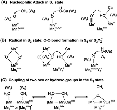 | ||
| Fig. 7 Suggested routes for O–O bond formation in the water-oxidizing cluster in photosystem II. Ws and Wf indicate the slow and fast exchanging substrate waters, respectively. For further details see the text. | ||
2.6 Summary: Principles of photosynthetic water-splitting
From the above text the following seven principles of photosynthetic water splitting can be extracted:1. The components of the primary photo-reactions as well as the Mn4OxCa cluster are supported by protective components and, once destroyed, automatically replaced by the organism by a specific repair mechanism.
2. A multimeric transition metal complex (Mn4OxCa cluster) is employed to couple the very fast one–electron photochemistry with several orders of magnitude slower four electron water-splitting chemistry.
3. The water-splitting catalyst is located in a sequestered environment; channels exist for substrate entry and product release.
4. The matrix (protein) around the Mn4OxCa cluster is highly important for the coupling of proton and electron transfer reactions. This feature is essential for achieving about equal redox potentials for all oxidation steps that match the oxidizing potential of the light-generated primary oxidant.
5. Point 4 leads to a decoupling of the release of the two products O2 and H+ from the catalytic site.
6. The substrate water molecules are stepwise prepared for O–O bond formation by binding to the Mn4OxCa cluster and by (partial) deprotonation. The concerted oxidation of the activated substrate occurs then either in two 2 e− or one concerted 4 e− reaction step(s). This avoids high energy intermediates.
7. The Mn4OxCa cluster undergoes several structural changes during the Kok cycle, which are probably significant for the mechanism. The surrounding matrix therefore needs to be flexible enough to support such changes.
2.7 Current homogeneous water-splitting catalysts
During billions of years of evolution nature has developed only one light-driven water-splitting catalyst, the above described Mn4OxCa cluster. Chemists are not restricted to the abundant, relatively non-toxic Mn, and have therefore created a small number of water-splitting complexes that are based on Ru99–105 or Ir106 (for reviews see refs. 13 and 107). These certified water-splitting catalysts drive water-splitting upon addition of CeIV or by electrochemistry. Also some Mn-based artificial systems exist,108,109 but in most cases only a small fraction of the evolved O2 originates in these latter models from true water oxidation, while the other O2 molecules contain at least one O-atom from the oxidant, which usually is an oxygen donor such as oxone.110 One possible exception is a linked di-Mn-porphyrin complex that was demonstrated to evolve correctly labeled dioxygen at defined redox potentials.111 To the best of our knowledge no visible light-driven homogenous water-splitting catalyst has been reported yet.112The current artificial complexes contain often two metal ions (only one in case of the Ir-complex) that have to undergo several oxidation state changes. In contrast, the four Mn ions in PSII cycle only between oxidation states MnIII and MnIV. Most complexes are, compared to PSII, still very unstable. Reported total turnover numbers lie between 1 and 3000. Mass spectrometry measurements often reveal in addition to O2 also CO2 evolution, which is a result of the oxidation of the organic ligands, either by the added strong oxidants or by the catalysts themselves. Recently a new interesting idea was presented in which two inorganic (SiW10) ligands were employed to stabilize a tetranuclear Ru complex.113 A stabilizing effect of a clay matrix has also been reported.114
While the progress with Ru- or Ir-based catalysts is currently more striking, we regard it still as important to also continue research on Mn-based catalysts, because Ir and Ru are relatively rare, expensive and toxic. Other interesting approaches for achieving light-driven water-splitting employ heterogeneous catalysis on doped TiO2 (for a review see ref. 115) or TiSi2.116
3. Hydrogen conversion
Hydrogen metabolism occurred already very early in evolution. It is established in all domains of life. In fact, it has been proposed that eukaryotic organisms have evolved through a symbiosis of methanogenic archea and hydrogen evolving prokaryots.117 The enzymes responsible for this metabolism are called “hydrogenases”. They catalyze the oxidation of molecular hydrogen into protons and electrons and the reduction of protons to produce molecular hydrogen by a heterolytic mechanism:| H2 ⇌ H+ + H− ⇌ 2H+ + 2e− | (6) |
Hydrogenases are interesting for the development of hydrogen-based fuel cells as well as for “photosynthetic cells” for hydrogen production. Reaction rates for these enzymes are very high; they lie in the range of 103–104 turnovers per second at 30 °C.118 It has been shown that hydrogenases when applied to graphite electrodes are as effective as Pt for proton reduction.119 The catalytic site contains the abundant and inexpensive metals Fe and Ni. A problem is that these enzymes are quite fragile and oxygen sensitive. In the following we will briefly describe structure and function of hydrogenases.
3.1 Hydrogenases
Based on the structure of the active site the enzymes are divided into three classes:(i) [Fe]-hydrogenases (formerly called metal free hydrogenases) contain one Fe atom coordinated with 2 CO and one H2O ligand.120 They are found in methanogenic archea and are exclusively specialized in H2 oxidation. An organic cofactor (methylenetetrahydromethanopterin) plays an essential role in the catalytic mechanism of this class of enzymes.
(ii) [FeFe]-hydrogenases (formerly called iron-only hydrogenases) contain a unique binuclear Fe cluster which is connected to a conventional cubane [4Fe4S] cluster. Here we find unusual CO and CN− ligands to the binuclear cluster. These hydrogenases occur in a wide variety of microorganisms, mostly however in anaerobic sulfur reducing bacteria15,121 and monocellular algae.122
(iii) [NiFe] hydrogenases contain a binuclear Ni–Fe complex coordinated by CO and CN− ligands. This group of hydrogenases is most widely distributed in nature and is relatively well studied.121,123 The enzymes occur in several types of bacteria living in regions with a higher oxygen concentration.
Quite a few sulfur reducing bacteria contain more than one type of hydrogenase. The family of Desulfovibrio (D). vulgaris contains [FeFe] as well as [NiFe] hydrogenases. It is assumed that they are involved in different metabolic functions in different cell compartments.124,125 The genetic regulation and interplay between these hydrogenases is not yet completely understood.
The increasing interest in renewable energy technology has stimulated the research into hydrogenases, in particular the ones which are active in hydrogen production. Below we review the design principles of the two major classes of hydrogenases ([NiFe] and [FeFe]) and discuss their functional features which may be employed in biotechnological hydrogen production.
3.2 Structural characteristics of hydrogenases
Fig. 8 shows a functional scheme of a hydrogenase enzyme. The substrate/product channels join at the active site where the redox reaction is taking place. The electron flow to and from the active site is relayed over a different path. Most [NiFe] and [FeFe] hydrogenases use “classical cubane” [4Fe4S] clusters for this purpose. Up to now, the crystal structures of five [NiFe] hydrogenases and two [FeFe] hydrogenases have been determined.126 They all originate from closely related sulfur reducing bacteria. It is however suspected that the corresponding enzymes from other organisms share the basic structural features of their respective active sites.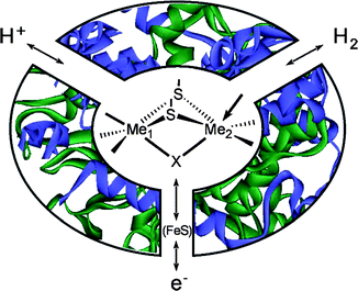 | ||
| Fig. 8 Schematic representation of a hydrogenase showing the S-bridged bimetallic catalytic center, the H+ and H2 channels and the electron transport chain. The open coordination site at one metal is indicated by an arrow. | ||
![Catalytic centers of [NiFe] hydrogenase (A) and [FeFe] hydrogenase (B) taken from the respective X-ray crystallographic structures.127,128,139–141 The putative site of H2 attachment is indicated by an arrow. For details see the text.](/image/article/2008/EE/b808792j/b808792j-f9.gif) | ||
| Fig. 9 Catalytic centers of [NiFe] hydrogenase (A) and [FeFe] hydrogenase (B) taken from the respective X-ray crystallographic structures.127,128,139–141 The putative site of H2 attachment is indicated by an arrow. For details see the text. | ||
3.3 Active and inactive states of hydrogenases
Similar to the water oxidizing complex in PS II the catalytic site in hydrogenases can exist in several different redox states. Midpoint potentials have been determined using spectroelectrochemistry.144–147 Structures of the intermediates resulted from different spectroscopic techniques.16,148,149 The various states are summarized below.![Scheme representing the different (spectroscopic) states of [NiFe] hydrogenase and their relationship. The formal oxidation states of Ni and Fe are indicated and the bridging ligand X (Fig. 9) is given in parentheses between metals. Paramagnetic (EPR-active) states are red, EPR-silent states blue. The states most probably involved in the catalytic cycle are placed in a shaded box (see also Fig. 13), for details see text and ref. 16. Reprinted with permission from ref 16. Copyright (2007) American Chemical Society.](/image/article/2008/EE/b808792j/b808792j-f10.gif) | ||
| Fig. 10 Scheme representing the different (spectroscopic) states of [NiFe] hydrogenase and their relationship. The formal oxidation states of Ni and Fe are indicated and the bridging ligand X (Fig. 9) is given in parentheses between metals. Paramagnetic (EPR-active) states are red, EPR-silent states blue. The states most probably involved in the catalytic cycle are placed in a shaded box (see also Fig. 13), for details see text and ref. 16. Reprinted with permission from ref 16. Copyright (2007) American Chemical Society. | ||
Upon reduction of Ni-B the enzyme passes through several EPR silent states: Ni-SIr (silent ready) and Ni-SIa (silent active). These states have been identified using FT-IR spectroscopy.152,153 After a two-electron reduction the EPR active Ni-C state is reached.154 In this redox state a hydrogen species has been identified using advanced EPR (HYSCORE, ENDOR) spectroscopy.155,156Fig. 11 shows the EPR spectrum of Ni-C as well as its FT-IR spectrum. In addition, the HYSCORE spectrum is depicted obtained from the hydrogenase activated using D2 in D2O. The obtained 2H hyperfine coupling is consistent with a hydride bridging the Ni-Fe unit. Upon illumination of this state at low temperature (<100 K) a different EPR spectrum is obtained assigned to Ni-L.157,158 It has been shown that the hydride species in Ni-L is dissociated from the Ni-Fe cluster.155,159 In fact, depending on the temperature and duration of the illumination different states Ni-L1, Ni-L2, Ni-L3 can be obtained indicating structural differences of the dissociation products.160 Raising the temperature above 120 K will recover the original Ni-C state, and the hydride species is shown to be reassociated with the Ni-Fe cluster. A last reduction step from Ni-C produces the EPR-silent Ni-R state which is the most reduced form of the active site. Exposure of Ni-C to CO gas will inhibit the enzyme and a different EPR spectrum Ni-CO(active) is generated.161 The Ni-CO state is also photosensitive and low-temperature illumination results in the same Ni-L state as obtained from Ni-C. DFT calculations of the electronic structure of the Ni-Fe cluster have been published with possible redox states of the individual Ni and Fe atoms.162 It is shown that Fe remains Fe(II) throughout all redox reactions. In the most oxidized (inactive) states Ni-A and Ni-B the Ni is proposed to be Ni(III) while in the intermediate reduced states Ni-SU, Ni-SIr, Ni-SIa it is Ni(II). Ni-C on the other hand is believed to have a Ni(III)(H−)Fe(II) configuration. Finally, the last reduction produces Ni-R in the Ni(II)(H−)Fe(II) configuration. It is still debated whether the Ni(II) states are low spin (diamagnetic) or high spin (S = 1).163
![Spectroscopic characterization of the active Ni-C state of [NiFe] hydrogenase of D. vulgaris Miyazaki F: (A) EPR (X-band, frozen state) showing the characteristic g tensor components; (B) HYSCORE (X-band at position gy)156 showing resonances from a coupled 14N (histidine)164 and the deuterium in the bridge between Ni and Fe (see panel D). (C) FTIR (room temperature) giving the vibrational frequencies of the CO and two CN− ligands at the iron, which are characteristic for the Ni-C state. (D) Structural model of the Ni-C state with a bridging hydride, based on the EPR,165 ENDOR and HYSCORE156 data. Panel B reprinted with permission from ref. 156. Copyright (2005) Springer-Verlag, Heidelberg.](/image/article/2008/EE/b808792j/b808792j-f11.gif) | ||
| Fig. 11 Spectroscopic characterization of the active Ni-C state of [NiFe] hydrogenase of D. vulgaris Miyazaki F: (A) EPR (X-band, frozen state) showing the characteristic g tensor components; (B) HYSCORE (X-band at position gy)156 showing resonances from a coupled 14N (histidine)164 and the deuterium in the bridge between Ni and Fe (see panel D). (C) FTIR (room temperature) giving the vibrational frequencies of the CO and two CN− ligands at the iron, which are characteristic for the Ni-C state. (D) Structural model of the Ni-C state with a bridging hydride, based on the EPR,165 ENDOR and HYSCORE156 data. Panel B reprinted with permission from ref. 156. Copyright (2005) Springer-Verlag, Heidelberg. | ||
![Scheme representing the different (spectroscopic) states of [FeFe] hydrogenase and their interconversion. The formal oxidation states of the binuclear subcluster and of the distal attached [4Fe4S] cluster are given as well as the putative ligand Y attached to the distal Fe (square brackets). The active states thought to be involved in the catalytic cycle are placed in the shaded box. For further details see text and ref. 16. Reprinted with permission from ref. 16. Copyright (2007) American Chemical Society.](/image/article/2008/EE/b808792j/b808792j-f12.gif) | ||
| Fig. 12 Scheme representing the different (spectroscopic) states of [FeFe] hydrogenase and their interconversion. The formal oxidation states of the binuclear subcluster and of the distal attached [4Fe4S] cluster are given as well as the putative ligand Y attached to the distal Fe (square brackets). The active states thought to be involved in the catalytic cycle are placed in the shaded box. For further details see text and ref. 16. Reprinted with permission from ref. 16. Copyright (2007) American Chemical Society. | ||
3.4 Oxygen sensitivity
The oxygen sensitivity of hydrogenases is of great importance with regards to the possible applications in the field of hydrogen fuel production, especially when the enzyme is combined with oxygen producing PSII (mimics). Interesting proposals have been put forward to immobilize PSII and a suitable hydrogenase on electrode surfaces separated by a membrane thus avoiding contact of the hydrogenases with oxygen.171 At the same time intense activities are deployed to genetically modify hydrogenases (i.e. generating mutants) in order to reduce their oxygen sensitivity. A few [NiFe] hydrogenases have been identified which show a surprising oxygen resistance. The membrane bound [NiFe] hydrogenase from Ralstonia eutropha153,172–174 is able to reduce protons (be it at a low rate) under oxygen pressure and recovers within 2 s to full activity when oxygen is removed.175 The basic structure of the active site in this hydrogenase does not differ from other [NiFe] hydrogenases so the reason for this oxygen resistance is not yet elucidated. In Table 1, a summary is presented on the oxygen sensitivity of various hydrogenases.| Enzyme, in order of position of organism in a pond (top to bottom) | Rate of anaerobic inactivation at pH 6 | Rate of activation after anaerobic inactivation | Reaction with O2 | Limiting rate constant for recovery from O2 (t1/2) |
|---|---|---|---|---|
| a Data are taken from Vincent et al.175 Table adapted from ref. 175 with permission. Copyright (2005) American Chemical Society. | ||||
| Ralstonia eutropha [NiFe]-MBH | Fast | Fast | Fast, reversible | 0.34 s−1 (2 s) |
| Allochromatium vinosum [NiFe]-hydrogenase | Slow | Fast | Fast, >90% reversible | 4.7 × 10⁻⁴ s−1 (25 min) |
| Desulfovibrio gigas [NiFe]-hydrogenase | Slow | Fast | Fast, >70% reversible | 3.3 × 10⁻⁴ s−1 (35 min) |
| Desulfovibrio desulfuricans [FeFe]-hydrogenase | Fast | Fast | Fast, irreversible | No recovery |
The oxygen sensitivity of [FeFe] hydrogenases is even more severe since the H-cluster is irreversibly destroyed upon reaction with oxygen. The Fe centers in the nuclear sub-cluster are probably oxidized to Fe(III) and lose their CO ligands. Nevertheless, some [FeFe] hydrogenase species seem to show a remarkable oxygen tolerance.176,177 This behavior might be correlated with the properties of the hydrophobic gas channel. It is assumed that H2 can diffuse much easier through the protein and reach the active site than O2 and CO. Therefore, much effort is put into the modification of the amino acids in the gas channel in particular of the hydrogenase form Chlamydomonas reinhardtii.178–180 But this is certainly not the only effect responsible for the (better) oxygen tolerance of several hydrogenases; also the geometric and electronic structure of the active site might play a role.
3.5. Proposed mechanisms of proton reduction and H2 oxidation
Hydrogenases, in contrast to PS II, are reversible enzymes and catalyze both hydrogen production and cleavage. In view of technical applications both reactions are interesting for catalysis: H2 production with regard to solar fuel production, and H2 cleavage for developing Pt-free fuel cell catalysts.181In Fig. 13 the two most recent models of the reaction are depicted. In both versions, H2 is initially bound to Ni. In the first model the proton is accepted by a loosely bound water to Fe(II), while in the second model it is accepted by the bridged hydride which is permanently present in the active states. In the first model, the Ni center is then reductively protonated (Ni-R) which releases the protons in a two-electron oxidation step. The second model assumes that the two protons are released in two subsequent single electron oxidation steps. Here H2 splitting is described, but it is assumed that the reverse reaction (H2 production) will occur through the same (reverse) pathway.
![Two proposed mechanisms for catalytic H2 oxidation by [NiFe] hydrogenase, see refs. 123, 182 and 189.](/image/article/2008/EE/b808792j/b808792j-f13.gif) | ||
| Fig. 13 Two proposed mechanisms for catalytic H2 oxidation by [NiFe] hydrogenase, see refs. 123, 182 and 189. | ||
![Proposed mechanism for the catalytic H2 production by [FeFe] hydrogenase.190 For details see text. Reprinted with permission from ref. 190. Copyright (2007) American Chemical Society.](/image/article/2008/EE/b808792j/b808792j-f14.gif)
3.6 Design principles of hydrogenases
For a better understanding of the design principles of native hydrogenases a comparison of the two major hydrogenases is useful.The two groups of hydrogenases have a completely different genetic background. Whereas the [NiFe] group is widely distributed in prokaryotes (mostly sulfur reducing bacteria), the [FeFe] group is less widely distributed but occurs in both prokaryots and eukaryots (algae, yeast). In fact, the genetic signature of the H-cluster is found in many higher organisms, even in homo sapiens. The [FeFe] hydrogenases are, in general, most active in H2 production while [NiFe] hydrogenases are more tuned to H2 oxidation. Both types are however bidirectional. Organisms employing [NiFe] hydrogenases are found in regions with higher oxygen levels than those using [FeFe] hydrogenase. This is because [FeFe] hydrogenases are extremely oxygen sensitive and will be inhibited irreversibly under O2. [NiFe] hydrogenases are, in general, more oxygen tolerant and some enzymes even evolve H2 under O2.
On the other hand, there are many similarities between the basic structures of the active site in both enzymes:
1. Both enzymes employ a bimetallic center where the chemistry is taking place.
2. Both active sites have a “butterfly-shaped” core in which the two metals are bridged by SR-ligands.
3. Only one of these metal atoms is redox active (Ni in [NiFe] and Fed in [FeFe] hydrogenase) and they both have a d7 configuration (Ni(III) and Fe(I), respectively) in their active states.
4. In both catalytic sites the Fe atom is kept at a low valence by the strongly donating ligands CN− and CO.
5. The metal-metal distance in both structures is short (2.5–2.9 Å), indicating a metal–metal bond.
6. One metal with an open coordination site can be identified in both active states. This is the site where H2 is believed to bind or is being released.
7. The H/D-isotope effect shows that in both cases the H2 splitting is heterolytic
8. In both active sites a sulfur or nitrogen/oxygen ligand probably acts as base to accept or donate the H+.
9. For both enzymes the catalytic activity is often inhibited by O2 and CO.
These features can serve as guidelines for the construction of biomimetic hydrogenase models.
3.7 Chemical model systems for the active sites in hydrogenases
The reduction of protons to molecular hydrogen – or vice versa – seems to be a much easier task to accomplish in model systems than light-induced water oxidation. The extensive structural and functional work on native hydrogenases over the last decade has stimulated the synthesis of a variety of metal-based model systems that might be used as electrocatalysts for hydrogen production or in fuel cells for hydrogen conversion. Considering the high price and low abundance of platinum, which is commonly used for such conversions, there is an urgent need for using sustainable metals such as iron and nickel as employed by nature in the hydrogenases. Important criteria for such catalysts are (i) robustness, i.e. a long-term stability, (ii) efficiency (high turnover frequency) and (iii) a low overpotential. These criteria are not easy to meet in model systems.191The work on biomimetic models for [NiFe] and [FeFe] hydrogenase has been described in several recent review articles.191–200 In this work many of the structural features important for proper function found in the native systems have been successfully incorporated, for example the bimetallic Ni–Fe or Fe–Fe core with rather short metal-metal distances, the sulfur-rich environment (terminal and bridging thiolate ligands), CO/CN ligation of the iron, the incorporation of a base for acceptance of the proton, and more recently of a hydride bridge.201 However, for none of the structural mimics of the active centers of the native systems a catalytic behavior has been reported so far leading to proton reduction or dihydrogen oxidation.
In this respect, other bioinspired model systems seem to be better suited as discussed in ref. 202. They contain for example dinuclear metal centers with Ru, Re or Ir. For a trinuclear NiFe2 complex203 some catalytic activity has also been reported. Furthermore, some mononuclear metal complexes catalyze proton electroreduction, but turnover numbers and frequencies are rather low.191 Recently, a promising dinuclear Ni–Ru complex has been described.204 It meets most of the criteria for a functional model and directly reacts with and heterolytically splits dihydrogen. This model incorporates a bridging hydride ligand, a crucial factor for proper function in [NiFe] hydrogenase. In the [FeFe] hydrogenase the hydride is most probably bound terminally to the distal iron. It has been proposed to use these differences in hydride binding as a criterion for hydrogenase models instead of the type of metal centers.202,204
In summary, structural model chemistry of hydrogenases is fairly advanced and nice spectroscopic results have been obtained for several systems, see e.g.refs. 201, 205 and 206. However, only a few functional models exist to date for hydrogenases. Their stability and turnover frequencies are still low and for all systems studied so far the overvoltage is very high, which represents a serious problem for their application in biotechnological devices.
An envisaged goal is the photocatalytic hydrogen production and conversion. First results in this promising field have already been described (see e.g.refs. 207 and 208 for a related review).
4. Conclusions
In this review the current state of the art in the understanding of the water oxidizing-complex and the hydrogenases is described. During recent years these fields have made considerable progress. However, several details are still missing, e.g. in case of water oxidation the exact mechanism of O–O bond formation at the Mn4OxCa cluster is not known, and for [FeFe] hydrogenases the crucial step of heterolytic H–H splitting/formation is still under debate.Understanding these biological processes will guide the progress in different avenues towards solar fuel production. The different attempts in that direction can be grouped as follows:
1. Genetic modification of cyanobacteria to increase their light-induced hydrogen production.
2. Genetic modification to convert existing proteins into artificial water-splitting catalysts that can be expressed, e.g. in E. coli.
3. De novo synthesis of water-splitting metalloproteins.
4. Chemical synthesis of biomimetic/bioinspired homogeneous catalysts, reaction centers and antenna systems.
5. Semiconductor based systems.
6. Heterogeneous catalysts that reduce the over potential during electrolysis and may for example be embedded in functional matrices on the surface of electrodes.
The optimization of biological organisms via genetic modifications may be the most promising approach on a short term. This will however require hydrogenases that are insensitive towards oxygen, and are more directly linked to the photosynthetic electron transport chain. Furthermore, competing metabolic reactions (cell growth/biomass production) of these organisms must be reduced by genetic manipulation and/or special culture conditions in order to maximize the H2 evolution rates so that they approach levels that are relevant for potential applications. Other problems concern the light access (optimization of antenna size), and the required space and costs of the bioreactors.142,209 Based on studies of the natural systems much has also been learned concerning the design principles required for biomimetic catalysts for water splitting and hydrogen evolution (see above sections). These include the use of abundant and inexpensive metals, the effective protection of the active sites in functional protein environments, and repair/replacement of active components in case of damage. For biomimetic chemistry it is to date clearly in far reach to mimic all these features – but many labs are working towards this goal by developing new approaches in the design and synthesis of such systems, encompassing not only the catalytic center, but also smart matrixes and the assembly via self organization.
More stable catalysts that do not require self repair, may be obtained by fully artificial catalytic systems that are totally different from the biological ones and only apply some basic principles learned from Nature. Other metals than Mn/Ca, Fe and Ni could be used, new ligand spheres and other matrices. For light harvesting, charge separation/stabilization and the effective coupling of the oxidizing/reducing equivalents to the redox catalysts different ways have been proposed; e.g. covalently linked molecular donor–acceptor systems, photovoltaic devises, semiconductor based systems and photoactive metal complexes (e.g. Ru-complexes).6,210
The aim of all these approaches is to develop catalytic systems that split water with sun light and produce hydrogen and oxygen, have a high efficiency and a long term stability. If such a system – either biological, biomimetic or bioinspired – has been developed there is hope to use it on a large scale to produce “solar fuels”, e.g. hydrogen or secondary products thereof. A remaining question is the availability of the sources “light” and “water”. The amount of (fresh) water necessary to be split for fuel production, i.e. to replace oil and coal on a long term can be estimated on the basis of the total primary energy consumption of Germany to be 30 l per day and person (assuming the same relative power conversion efficiencies for oil and H2). For 10 h of useable sunlight per day this corresponds to ≈ 1 ml H2O (0.05 mol) per second. For a turnover frequency of 1000 s−1 this requires 50 μmol of catalyst per person. Clearly, scientists are currently facing very large challenges to solve these scientific, strategic and logistic problems. But these problems must be overcome – otherwise mankind will not be able to survive when fossil fuels are extinguished on our planet.
Acknowledgements
This work has been supported by the Max Planck Society, the EU/Energy Network project SOLAR-H2 (FP7 contract 212508) and BMBF (Bio-H2).References
- Govindjee, Advances in Photosynthesis and Respiration, ed. Govindjee, Springer, Dordrecht, 1994–2008, vol. 1–26 Search PubMed.
- R. E. Blankenship, Molecular Mechanisms of Photosynthesis, Blackwell Science Ltd., Oxford, 2002 Search PubMed.
- G. Renger, Primary Processes of Photosynthesis - Part 1 and 2. Principles and Apparatus, ed. G. Renger, Comprehensive series in Photochemical & Photobiological Sciences, RSC Publishing, Cambridge, 2008 Search PubMed.
- International Energy Agency (ed.), World Energy Outlook 2008, Organisation for Economic Co-operation and Development OECD, 2008 Search PubMed.
- Intergovernmental Panel on Climate Change (ed.), Fourth Assessment Report, 2007 Search PubMed.
- N. S. Lewis and D. G. Nocera, Proc. Natl. Acad. Sci. U. S. A., 2006, 103, 15729 CrossRef CAS.
- N. Armaroli and V. Balzani, Angew. Chem., Int. Ed., 2007, 46, 52 CrossRef CAS.
- R. Cammack, M. Frey, R. Robson, Hydrogen as a Fuel: Learning from Nature, Taylor & Francis, London and New York, 2001 Search PubMed.
- P. Hoffmann, Tomorrow's Energy. Hydrogen, Fuel Cells, and the Prospects for a Cleaner Planet, The MIT Press, Cambridge, 2002 Search PubMed.
- D. C. J. Sperling, The Hydrogen Energy Transition: Moving Toward the Post Petroleum Age in Transportation, Elsevier Academic Press, San Diego, CA, 2004 Search PubMed.
- W. Lubitz and W. Tumas, Chem. Rev., 2007, 107, 3900 CrossRef.
- A. F. Collings and Ch. Critchley, Artificial Photosynthesis: From Basic Biology to Industrial Application, Wiley-VCH Verlag GmbH, Weinheim, 2005 Search PubMed.
- J. H. Alstrum-Acevedo, M. K. Brennaman and T. J. Meyer, Inorg. Chem., 2005, 44, 6802 CrossRef CAS.
- T. J. Wydrzynski and K. Satoh, Photosystem II. The Light-Driven Water: Plastoquinone Oxidoreductase, ed. T. J. Wydrzynski and K. Satoh, in Advances in Photosynthesis and Respiration, Springer, Dordrecht, 2005, vol. 22 Search PubMed.
- P. M. Vignais and B. Billoud, Chem. Rev., 2007, 107, 4206 CrossRef CAS.
- W. Lubitz, E. Reijerse and M. van Gastel, Chem. Rev., 2007, 107, 4331 CrossRef CAS.
- Y. Nicolet, C. Piras, P. Legrand, C. E. Hatchikian and J. C. Fontecilla-Camps, Struct. Fold. Des., 1999, 7, 13 CrossRef CAS.
- B. Loll, J. Kern, W. Saenger, A. Zouni and J. Biesiadka, Nature, 2005, 438, 1040 CrossRef CAS.
- M. Kirch, J. M. Lehn and J. P. Sauvage, Helv. Chim. Acta, 1979, 62, 1345 CrossRef CAS.
- A. Melis and T. Happe, Photosynth. Res., 2004, 80, 401 CrossRef CAS.
- M. L. Ghirardi, P. King, S. Kosourov, M. Forestier, L. Zhang and M. Seibert, Development of Algal Systems for Hydrogen Photoproduction: Addressing the Hydrogenase Oxygen-sensitivity Problem, in Artificial Photosynthesis, ed. A. F. Collings and Ch. Critchley, Wiley-VCH Verlag GmbH, Weinheim, 2005, 213 Search PubMed.
- T. Happe, A. Hemschemeier, M. Winkler and A. Kaminski, Trends Plant Sci., 2002, 7, 246 CrossRef CAS.
- J. Miyake, Y. Igarashi and M. Rögner, Biohydrogen III, Elsevier, Amsterdam, 2004 Search PubMed.
- G. C. Dismukes and R. E. Blankenship, The Origin and Evolution of Photosynthetic Oxygen Production, in Photosystem II. The Light-Driven Water: Plastoquinone Oxidoreductase, ed. T. Wydrzynski and K. Satoh, Advances in Photosynthesis and Respiration, Springer, Dordrecht, 2005, vol. 22, 683 Search PubMed.
- J. Raymond and R. E. Blankenship, Coord. Chem. Rev., 2008, 252, 377 CrossRef CAS.
- J. Messinger, Phys. Chem. Chem. Phys., 2004, 6, 4764 RSC.
- R. D. Britt, K. A. Campbell, J. M. Peloquin, M. L. Gilchrist, C. P. Aznar, M. M. Dicus, J. Robblee and J. Messinger, Biochim. Biophys. Acta, 2004, 1655, 158 CrossRef CAS.
- W. Hillier and J. Messinger, Mechanism of Photosynthetic Oxygen Production, in Photosystem II. The Light-Driven Water: Plastoquinone Oxidoreductase, ed. T. Wydrzynski and K. Satoh, Advances in Photosynthesis and Respiration, Springer, Dordrecht, 2005, vol. 22, 567 Search PubMed.
- N. Nelson and C. F. Yocum, Annu. Rev. Plant Biol., 2006, 57, 521 Search PubMed.
- J. P. McEvoy and G. W. Brudvig, Chem. Rev., 2006, 106, 4455 CrossRef CAS.
- J. Kern and G. Renger, Photosynth. Res., 2007, 94, 183 CrossRef CAS.
- G. Renger, Photosynth. Res., 2007, 92, 407 CrossRef CAS.
- J. Messinger and G. Renger, Photosynthetic Water Splitting, in Primary Processes of Photosynthesis - Part 2: Basic Principles and Apparatus, ed. G. Renger, Comprehensive Series in Photochemical and Photobiological Sciences, The Royal Society of Chemistry, Cambridge, UK, 2008, 291 Search PubMed.
- J. Yano and V. K. Yachandra, Inorg. Chem., 2008, 47, 1711 CrossRef CAS.
- K. N. Ferreira, T. M. Iverson, K. Maghlaoui, J. Barber and S. Iwata, Science, 2004, 303, 1831 CrossRef CAS.
- C. F. Yocum, Coord. Chem. Rev., 2008, 252, 296 CrossRef CAS.
- H. J. van Gorkom and C. F. Yocum, The calcium and chloride cofactors, in Photosystem II. The Light-Driven Water: Plastoquinone Oxidoreductase, ed. T. Wydrzynski and K. Satoh, Advances in Photosynthesis and Respiration, Springer, Dordrecht, 2005, vol. 22, 307 Search PubMed.
- L. M. C. Barter, D. R. Klug and R. van Grondelle, Energy Trapping and Equilibration: A Balance of Regulation and Efficiency, in Photosystem II. The Light-Driven Water: Plastoquinone Oxidoreductase, ed. T. Wydrzynski and K. Satoh, Advances in Photosynthesis and Respiration, Springer, Dordrecht, 2005, vol. 22, 491 Search PubMed.
- G. Renger and A. R. Holzwarth, Primary electron transfer, in Photosystem II. The Light-Driven Water: Plastoquinone Oxidoreductase, ed. T. Wydrzynski and K. Satoh, Advances in Photosynthesis and Respiration, Springer, Dordrecht, 2005, vol. 22, 139 Search PubMed.
- F. Rappaport, M. Guergova-Kuras, P. J. Nixon, B. A. Diner and J. Lavergne, Biochemistry, 2002, 41, 8518 CrossRef CAS.
- J. Messinger and G. Renger, Biochemistry, 1994, 33, 10896 CrossRef CAS.
- J. Messinger, W. P. Schröder and G. Renger, Biochemistry, 1993, 32, 7658 CrossRef CAS.
- M. Grabolle and H. Dau, Physiol Plantarum, 2007, 131, 50 Search PubMed.
- L. N. Bell, N. D. Gudkov, Thermodynamics of Light Energy Conversion, in Topics in Photosynthesis: The Photosystems: Structure, Function and Molecular Biology, ed. J. Barber, Kluwer Academic Publisher, Dordrecht, 1992, vol. 17 Search PubMed.
- F. M. Ho and S. Styring, Biochim. Biophys. Acta, 2008, 1777, 140 CAS.
- J. W. Murray and J. Barber, J. Struct. Biol., 2007, 159, 228 CrossRef CAS.
- J. Yano, J. Kern, K. Sauer, M. J. Latimer, Y. Pushkar, J. Biesiadka, B. Loll, W. Saenger, J. Messinger, A. Zouni and V. K. Yachandra, Science, 2006, 314, 821 CrossRef CAS.
- N. Kamiya and J. R. Shen, Proc. Natl. Acad. Sci. U. S. A., 2003, 100, 98 CrossRef CAS.
- J. Yano, J. Kern, K. D. Irrgang, M. J. Latimer, U. Bergmann, P. Glatzel, Y. Pushkar, J. Biesiadka, B. Loll, K. Sauer, J. Messinger, A. Zouni and V. K. Yachandra, Proc. Natl. Acad. Sci. U. S. A., 2005, 102, 12047 CrossRef CAS.
- R. M. Cinco, J. H. Robblee, A. Rompel, C. Fernandez, V. K. Yachandra, K. Sauer and M. P. Klein, J. Phys. Chem. B, 1998, 102, 8248 CrossRef CAS.
- R. M. Cinco, K. L. M. Holman, J. H. Robblee, J. Yano, S. A. Pizarro, E. Bellacchio, K. Sauer and V. K. Yachandra, Biochemistry, 2002, 41, 12928 CrossRef CAS.
- R. M. Cinco, J. H. Robblee, J. Messinger, C. Fernandez, K. L. M. Holman, K. Sauer and V. K. Yachandra, Biochemistry, 2004, 43, 13271 CrossRef CAS.
- E. M. Sproviero, J. A. Gascon, J. P. McEvoy, G. W. Brudvig and V. S. Batista, J. Am. Chem. Soc., 2008, 130, 3428 CrossRef CAS.
- S. Zein, L. V. Kulik, J. Yano, J. Kern, Y. Pushkar, A. Zouni, V. K. Yachandra, W. Lubitz, F. Neese and J. Messinger, Philos. Trans. R. Soc. London, Ser. B: Biol. Sci., 2008, 363, 1167 CrossRef CAS.
- P. E. M. Siegbahn, Chem.-Eur. J., 2006, 12, 9217 CrossRef CAS.
- J. Barber and J. W. Murray, Coord. Chem. Rev., 2008, 252, 233 CrossRef.
- M. Haumann, M. Barra, P. Loja, S. Loscher, R. Krivanek, A. Grundmeier, L. E. Andreasson and H. Dau, Biochemistry, 2006, 45, 13101 CrossRef CAS.
- V. V. Klimov, R. J. Hulsebosch, S. I. Allakhverdiev, H. Wincencjusz, H. J. van Gorkom and A. J. Hoff, Biochemistry, 1997, 36, 16277 CrossRef CAS.
- C. Aoyama, H. Suzuki, M. Sugiura and T. Noguchi, Biochemistry, 2008, 47, 2760 CrossRef CAS.
- G. Ulas, G. Olack and G. W. Brudvig, Biochemistry, 2008, 47, 3073 CrossRef CAS.
- D. Shevela, J. H. Su, V. Klimov and J. Messinger, Biochim. Biophys. Acta: Bioenergetics, 2008, 1777, 532 CrossRef CAS.
- J. H. Robblee, J. Messinger, R. M. Cinco, K. L. McFarlane, C. Fernandez, S. A. Pizarro, K. Sauer and V. K. Yachandra, J. Am. Chem. Soc., 2002, 124, 7459 CrossRef CAS.
- W. C. Liang, T. A. Roelofs, R. M. Cinco, A. Rompel, M. J. Latimer, W. O. Yu, K. Sauer, M. P. Klein and V. K. Yachandra, J. Am. Chem. Soc., 2000, 122, 3399 CrossRef CAS.
- M. Haumann, C. Müller, P. Liebisch, L. Iuzzolino, J. Dittmer, M. Grabolle, T. Neisius, W. Meyer-Klaucke and H. Dau, Biochemistry, 2005, 44, 1894 CrossRef CAS.
- B. Kok, B. Forbush and M. McGloin, Photochem. Photobiol., 1970, 11, 457 CrossRef CAS.
- P. Joliot, G. Barbieri and R. Chabaud, Photochem. Photobiol., 1969, 10, 309 CrossRef CAS.
- P. A. Jursinic and R. J. Dennenberg, Biochim. Biophys. Acta, 1990, 1020, 195 CAS.
- M. R. Razeghifard and R. J. Pace, Biochemistry, 1999, 38, 1252 CrossRef CAS.
- J. G. Metz, P. J. Nixon, M. Rogner, G. W. Brudvig and B. A. Diner, Biochemistry, 1989, 28, 6960 CrossRef CAS.
- K. Brettel, E. Schlodder and H. T. Witt, Biochim. Biophys. Acta, 1984, 766, 403 CrossRef CAS.
- H.-J. Eckert and G. Renger, FEBS Lett., 1988, 236, 425 CrossRef CAS.
- N. Ishida, M. Sugiura, F. Rappaport, T.-L. Lai, A. W. Rutherford and A. Boussac, J. Biol. Chem., 2008, 283, 13330 CrossRef CAS.
- S. V. Baranov, G. M. Ananyev, V. V. Klimov and G. C. Dismukes, Biochemistry, 2000, 39, 6060 CrossRef CAS.
- J. Messinger, M. Badger and T. Wydrzynski, Proc. Natl. Acad. Sci. U. S. A., 1995, 92, 3209 CAS.
- G. Hendry and T. Wydrzynski, Biochemistry, 2003, 42, 6209 CrossRef CAS.
- J. S. Vrettos, D. A. Stone and G. W. Brudvig, Biochemistry, 2001, 40, 7937 CrossRef CAS.
- W. Hillier and T. Wydrzynski, Biochemistry, 2000, 39, 4399 CrossRef CAS.
- G. Hendry and T. Wydrzynski, Biochemistry, 2002, 41, 13328 CrossRef CAS.
- W. Hillier, J. Messinger and T. Wydrzynski, Biochemistry, 1998, 37, 16908 CrossRef CAS.
- J. H. Su, W. Lubitz and J. Messinger, J. Am. Chem. Soc., 2008, 130, 786 CrossRef CAS.
- L. V. Kulik, B. Epel, W. Lubitz and J. Messinger, J. Am. Chem. Soc., 2005, 127, 2392 CrossRef CAS.
- L. V. Kulik, B. Epel, W. Lubitz and J. Messinger, J. Am. Chem. Soc., 2007, 129, 13421 CrossRef CAS.
- V. K. Yachandra, K. Sauer and M. P. Klein, Chem. Rev., 1996, 96, 2927 CrossRef CAS.
- G. C. Dismukes and Y. Siderer, Proc. Natl. Acad. Sci. U. S. A., 1981, 78, 274 CAS.
- J. Messinger, J. H. A. Nugent and M. C. W. Evans, Biochemistry, 1997, 36, 11055 CrossRef CAS.
- J. Messinger, J. H. Robblee, W. O. Yu, K. Sauer, V. K. Yachandra and M. P. Klein, J. Am. Chem. Soc., 1997, 119, 11349 CrossRef CAS.
- K. A. Ahrling, S. Peterson and S. Styring, Biochemistry, 1997, 36, 13148 CrossRef.
- J. M. Peloquin, K. A. Campbell, D. W. Randall, M. A. Evanchik, V. L. Pecoraro, W. H. Armstrong and R. D. Britt, J. Am. Chem. Soc., 2000, 122, 10926 CrossRef CAS.
- J. Messinger, J. H. Robblee, U. Bergmann, C. Fernandez, P. Glatzel, H. Visser, R. M. Cinco, K. L. McFarlane, E. Bellacchio, S. A. Pizarro, S. P. Cramer, K. Sauer, M. P. Klein and V. K. Yachandra, J. Am. Chem. Soc., 2001, 123, 7804 CrossRef CAS.
- P. Glatzel, U. Bergmann, J. Yano, H. Visser, J. H. Robblee, W. W. Gu, F. M. F. de Groot, G. Christou, V. L. Pecoraro, S. P. Cramer and V. K. Yachandra, J. Am. Chem. Soc., 2004, 126, 9946 CrossRef CAS.
- F. A. Armstrong, Philos. Trans. R. Soc. London, Ser. B: Biol. Sci., 2008, 363, 1263 CrossRef CAS.
- V. L. Pecoraro, M. J. Baldwin, M. T. Caudle, W. Y. Hsieh and N. A. Law, Pure Appl. Chem., 1998, 70, 925 CrossRef CAS.
- M. Haumann and W. Junge, Biochim. Biophys. Acta, 1999, 1411, 86.
- P. E. M. Siegbahn, Inorg. Chem., 2000, 39, 2923 CrossRef CAS.
- C. W. Hoganson and G. T. Babcock, Science, 1997, 277, 1953 CrossRef CAS.
- F. Rappaport, M. Blanchard-Desce and J. Lavergne, Biochim. Biophys. Acta, 1994, 1184, 178 CrossRef CAS.
- M. Haumann, P. Liebisch, C. Müller, M. Barra, M. Grabolle and H. Dau, Science, 2005, 310, 1019 CrossRef CAS.
- T. J. Meyer, M. H. V. Huynh and H. H. Thorp, Angew. Chem., Int. Ed., 2007, 46, 5304.
- S. W. Gersten, G. J. Samuels and T. J. Meyer, J. Am. Chem. Soc., 1982, 104, 4029 CrossRef CAS.
- F. P. Rotzinger, S. Munavalli, P. Comte, J. K. Hurst, M. Gratzel, F. J. Pern and A. J. Frank, J. Am. Chem. Soc., 1987, 109, 6619 CrossRef CAS.
- R. Zong and R. P. Thummel, J. Am. Chem. Soc., 2005, 127.
- T. A. Betley, Y. Surendranath, M. V. Childress, G. E. Alliger, R. Fu, C. C. Cummins and D. G. Nocera, Philos. Trans. R. Soc. London, Ser. B: Biol. Sci., 2008, 363, 1293 CrossRef CAS.
- M. Rodriguez, I. Romero, C. Sens and A. Llobet, J. Mol. Catal. A: Chem., 2006, 251, 215 CrossRef CAS.
- I. Romero, M. Rodriguez, C. Sens, J. Mola, M. R. Kollipara, L. Francas, E. Mas-Marza, L. Escriche and A. Llobet, Inorg. Chem., 2008, 47, 1824 CrossRef CAS.
- C. Sens, I. Romero, M. Rodriguez, A. Llobet, T. Parella and J. Benet-Buchholz, J. Am. Chem. Soc., 2004, 126, 7798 CrossRef CAS.
- N. D. McDaniel, F. J. Coughlin, L. L. Tinker and S. Bernhard, J. Am. Chem. Soc., 2008, 130, 210 CrossRef CAS.
- F. Liu, J. J. Concepcion, J. W. Jurss, T. Cardolaccia, J. L. Templeton and T. J. Meyer, Inorg. Chem., 2008, 47, 1727 CrossRef CAS.
- J. Limburg, J. S. Vrettos, H. Chen, J. C. Paula, R. H. Crabtree and G. W. Brudvig, J. Am. Chem. Soc., 2001, 123, 423 CrossRef CAS.
- J. Limburg, J. S. Vrettos, L. M. Liable-Sands, A. L. Rheingold, R. H. Crabtree and G. W. Brudvig, Science, 1999, 283, 524 CrossRef CAS.
- P. Kurz, G. Berggren, M. F. Anderlund and S. Styring, Dalton Trans., 2007, 4258 RSC.
- Y. Naruta, M. Sasayama and T. Sasaki, Angew. Chem., Int. Ed. Engl., 1994, 33, 1839 CrossRef.
- C. Herrero, B. Lassalle-Kaiser, W. Leibl, A. W. Rutherford and A. Aukauloo, Coord. Chem. Rev., 2008, 252, 456 CrossRef CAS.
- Y. V. Geletii, P. Kögerler, D. A. Hillesheim, D. G. Musaev and C. L. Hill, Angew. Chem., 2008, 120, 3960 CrossRef.
- M. Yagi and K. Narita, J. Am. Chem. Soc., 2004, 126, 8084 CrossRef CAS.
- M. Yagi and M. Kaneko, Chem. Rev., 2001, 101, 21 CrossRef CAS.
- P. Ritterskamp, A. Kuklya, M. A. Wustkamp, K. Kerpen, C. Weidenthaler and M. Demuth, Angew. Chem., Int. Ed., 2007, 46, 7770 CrossRef CAS.
- W. Martin and M. Müller, Nature, 1998, 392, 37 CrossRef CAS.
- H. R. Pershad, J. L. C. Duff, H. A. Heering, E. C. Duin, S. P. J. Albracht and F. A. Armstrong, Biochemistry, 1999, 38, 8992 CrossRef CAS.
- C. Leger, A. K. Jones, W. Roseboom, S. P. J. Albracht and F. A. Armstrong, Biochemistry, 2002, 41, 15736 CrossRef CAS.
- S. Shima and R. K. Thauer, Chem. Rec., 2007, 7, 37 CrossRef CAS.
- P. M. Vignais, B. Billoud and J. Meyer, FEMS Microbiol. Rev., 2001, 25, 455 CrossRef CAS.
- M. L. Ghirardi, M. C. Posewitz, P. C. Maness, A. Dubini, J. P. Yu and M. Seibert, Annu. Rev. Plant Biol., 2007, 58, 71 Search PubMed.
- W. Lubitz, M. van Gastel and W. Gärtner, Met. Ions. Life. Sci., 2007, 2, 279 Search PubMed.
- S. A. Caffrey, H. S. Park, J. K. Voordouw, Z. He, J. Zhou and G. Voordouw, J. Bacteriol., 2007, 189, 6159 CrossRef CAS.
- I. A. C. Pereira, C. V. Romao, A. V. Xavier, J. LeGall and M. Teixeira, J. Biol. Inorg. Chem., 1998, 3, 494 CrossRef CAS.
- J. C. Fontecilla-Camps, A. Volbeda, C. Cavazza and Y. Nicolet, Chem. Rev., 2007, 107, 4273 CrossRef CAS.
- A. Volbeda, E. Garcin, C. Piras, A. L. De Lacey, V. M. Fernandez, E. C. Hatchikian, M. Frey and J. C. Fontecilla-Camps, J. Am. Chem. Soc., 1996, 118, 12989 CrossRef CAS.
- A. Volbeda, L. Martin, C. Cavazza, M. Matho, B. W. Faber, W. Roseboom, S. P. J. Albracht, E. Garcin, M. Rousset and J. C. Fontecilla-Camps, J. Biol. Inorg. Chem., 2005, 10, 239 CrossRef CAS.
- C. C. Page, C. C. Moser, X. X. Chen and P. L. Dutton, Nature, 1999, 402, 47 CrossRef CAS.
- Y. Higuchi, T. Yagi and N. Yasuoka, Structure, 1997, 5, 1671 CrossRef CAS.
- M. Carepo, D. L. Tierney, C. D. Brondino, T. C. Yang, A. Pamplona, J. Telser, I. Moura, J. J. G. Moura and B. M. Hoffman, J. Am. Chem. Soc., 2002, 124, 281 CrossRef CAS.
- P. M. Matias, C. M. Soares, L. M. Saraiva, R. Coelho, J. Morais, J. LeGall and M. A. Carrando, J. Biol. Inorg. Chem., 2001, 6, 63 CrossRef CAS.
- K. A. Vincent, N. A. Belsey, W. Lubitz and F. A. Armstrong, J. Am. Chem. Soc., 2006, 128, 7448 CrossRef CAS.
- Y. Montet, P. Amara, A. Volbeda, X. Vernede, E. C. Hatchikian, M. J. Field, M. Frey and J. C. Fontecilla-Camps, Nat. Struct. Biol., 1997, 4, 523 CrossRef CAS.
- M. Frey, J. C. Fontecilla-Camps and A. Volbeda, Nickel-iron hydrogenases, in: Handbook of Metalloproteins, ed. A. Messerschmidt, R. Huber, T. Poulos and K. Wieghardt, John Wiley & Sons, Ltd., Chichester, 2001, p. 880 Search PubMed.
- A. Volbeda and J. C. Fontecilla-Camps, Coord. Chem. Rev., 2005, 249, 1609 CrossRef CAS.
- A. Volbeda and J. C. Fontecilla-Camps, Dalton Trans., 2003, 4030 RSC.
- H. Ogata, Y. Mizogushi, N. Mizuno, K. Miki, S. Adachi, N. Yasuoka, T. Yagi, O. Yamauchi, S. Hirota and Y. Higuchi, J. Am. Chem. Soc., 2002, 124, 11628 CrossRef CAS.
- Y. Nicolet, A. L. De Lacey, X. Vernede, V. M. Fernandez, E. C. Hatchikian and J. C. Fontecilla-Camps, J. Am. Chem. Soc., 2001, 123, 1596 CrossRef CAS.
- Y. Nicolet, C. Cavazza and J. C. Fontecilla-Camps, J. Inorg. Biochem., 2002, 91, 1 CrossRef CAS.
- Y. Nicolet, B. J. Lemon, J. C. Fontecilla-Camps and J. W. Peters, Trends Biochem. Sci., 2000, 25, 138 CrossRef CAS.
- A. Hemschemeier, S. Fouchard, L. Cournac, G. Peltier and T. Happe, Planta, 2008, 227, 397 CAS.
- A. S. Pandey, T. V. Harris, L. J. Giles, J. W. Peters and R. K. Szilagyi, J. Am. Chem. Soc., 2008, 130, 4533 CrossRef CAS.
- A. L. De Lacey, E. C. Hatchikian, A. Volbeda, M. Frey, J. C. Fontecilla-Camps and V. M. Fernandez, J. Am. Chem. Soc., 1997, 119, 7181 CrossRef CAS.
- C. Fichtner, Ch. Laurich, E. Bothe and W. Lubitz, Biochemistry, 2006, 45, 9706 CrossRef CAS.
- B. Bleijlevens, F. van Broekhuizen, A. L. De Lacey, W. Roseboom, V. M. Fernandez and S. P. J. Albracht, J. Biol. Inorg. Chem., 2004, 9, 743 CAS.
- S. Best, Coord. Chem. Rev., 2005, 249, 1536 CrossRef CAS.
- A. L. De Lacey, V. M. Fernandez, M. Rousset and R. Cammack, Chem. Rev., 2007, 107, 4304 CrossRef CAS.
- W. Roseboom, A. L. De Lacey, V. M. Fernandez, C. Hatchikian and S. P. J. Albracht, J. Biol. Inorg. Chem., 2006, 11, 102 CrossRef CAS.
- S. P. J. Albracht, Biochim. Biophys. Acta, 1994, 1188, 167 CAS.
- K. A. Vincent, A. Parkin and F. A. Armstrong, Chem. Rev., 2007, 107, 4366 CrossRef CAS.
- J. M. C. C. Coremans, J. W. van der Zwaan and S. P. J. Albracht, Biochim. Biophys. Acta, 1992, 1119, 157 CAS.
- B. Bleijlevens, T. Buhrke, E. Van der Linden, B. Friedrich and S. P. J. Albracht, J. Biol. Chem., 2004, 279, 46686 CrossRef CAS.
- J. M. C. C. Coremans, C. J. van Garderen and S. P. J. Albracht, Biochim. Biophys. Acta, 1992, 1119, 148 CAS.
- M. Brecht, M. van Gastel, T. Buhrke, B. Friedrich and W. Lubitz, J. Am. Chem. Soc., 2003, 125, 13075 CrossRef CAS.
- S. Foerster, M. van Gastel, M. Brecht and W. Lubitz, J. Biol. Inorg. Chem., 2005, 10, 51 CrossRef CAS.
- R. Cammack, D. S. Patil, E. C. Hatchikian and V. M. Fernandez, Biochim. Biophys. Acta, 1986, 912, 98.
- J. W. van der Zwaan, S. P. J. Albracht, R. D. Fontijn and E. C. Slater, FEBS Lett., 1985, 2, 271 CrossRef CAS.
- C. Fichtner, M. van Gastel and W. Lubitz, Phys. Chem. Chem. Phys., 2003, 5, 5507 RSC.
- M. Medina, R. Williams and R. Cammack, J. Chem. Soc., Faraday Trans., 1994, 90, 2921 RSC.
- R. P. Happe, W. Roseboom and S. P. J. Albracht, Eur. J. Biochem., 1999, 259, 602 CrossRef CAS.
- M. Stein, Doctoral Thesis, Technische UniversitätBerlin, 2001.
- H. Wang, D. S. Patil, W. Gu, L. Jacquamet, S. Friedrich, T. Funk and S. P. Cramer, J. Electron Spectrosc. Relat. Phenom., 2001, 114-116, 855 CrossRef.
- A. G. Agrawal, M. van Gastel, W. Gärtner and W. Lubitz, J. Phys. Chem. B, 2006, 110, 8142 CrossRef CAS.
- S. Foerster, M. Stein, M. Brecht, H. Ogata, Y. Higuchi and W. Lubitz, J. Am. Chem. Soc., 2003, 125, 83 CrossRef CAS.
- D. S. Patil, J. J. G. Moura, S. H. He, M. Teixeira, B. C. Prickril, D. V. DerVartanian, H. D. Peck, J. LeGall and B. H. Huynh, J. Biol. Chem., 1988, 263, 18732 CAS.
- A. S. Pereira, P. Tavares, I. Moura, J. J. G. Moura and B. H. Huynh, J. Am. Chem. Soc., 2001, 123, 2771 CrossRef CAS.
- A. J. Pierik, W. R. Hagen, J. S. Redeker, R. B. G. Wolbert, M. Boersma, M. F. J. M. Verhagen, H. J. Grande, C. Veeger, P. H. A. Mutsaers, R. H. Sands and W. R. Dunham, Eur. J. Biochem., 1992, 209, 63 CAS.
- C. Kamp, A. Silakov, M. Winkler, E. Reijerse, W. Lubitz and T. Happe, Biochim. Biophys. Acta, 2008, 1777, 410 CAS.
- A. Silakov, E. J. Reijerse, S. P. J. Albracht, E. C. Hatchikian and W. Lubitz, J. Am. Chem. Soc., 2007, 129, 11447 CrossRef CAS.
- B. Esper, A. Badura and M. Rögner, Trends Plant Sci., 2006, 11, 543 CrossRef CAS.
- T. Buhrke, O. Lenz, N. Krauss and B. Friedrich, J. Biol. Chem., 2005, 280, 23791 CrossRef CAS.
- T. Burgdorf, O. Lenz, T. Buhrke, E. Van der Linden, A. K. Jones, S. P. J. Albracht and B. Friedrich, J. Mol. Microbiol. Biotechnol., 2005, 10, 181 CrossRef CAS.
- E. Van der Linden, T. Burgdorf, M. Bernhard, B. Bleijlevens, B. Friedrich and S. P. J. Albracht, J. Biol. Inorg. Chem., 2004, 9, 616 CAS.
- K. A. Vincent, A. Parkin, O. Lenz, S. P. J. Albracht, J. C. Fontecilla-Camps, R. Cammack, B. Friedrich and F. A. Armstrong, J. Am. Chem. Soc., 2005, 127, 18179 CrossRef CAS.
- C. Baffert, M. Demuez, L. Cournac, B. Burlat, B. Guigliarelli, P. Bertrand, L. Girbal and C. Leger, Angew. Chem., Int. Ed., 2008, 47, 2052 CrossRef CAS.
- S. C. E. Tosatto, S. Toppo, D. Carbonera, G. M. Giacometti and P. Costantini, Int. J. Hydrogen Energy, 2008, 33, 570 CrossRef CAS.
- J. Cohen, K. Kim, P. King, M. Seibert and K. Schulten, Structure, 2005, 13, 1321 CrossRef CAS.
- J. Cohen, K. Kim, M. Posewitz, M. L. Ghirardi, K. Schulten, M. Seibert and P. King, Biochem. Soc. Trans., 2005, 33, 80 CrossRef CAS.
- M. L. Ghirardi, P. W. King, M. C. Posewitz, P. C. Maness, A. Fedorov, K. Kim, J. Cohen, K. Schulten and M. Seibert, Biochem. Soc. Trans., 2005, 33, 70 CrossRef CAS.
- K. A. Vincent, J. A. Cracknell, O. Lenz, I. Zebger, B. Friedrich and F. A. Armstrong, Proc. Natl. Acad. Sci. U. S. A., 2005, 102, 16951 CrossRef CAS.
- M. Stein and W. Lubitz, J. Inorg. Biochem., 2004, 98, 862 CrossRef CAS.
- L. De Gioia, P. Fantucci, B. Guigliarelli and P. Bertrand, Inorg. Chem., 1999, 38, 2658 CrossRef CAS.
- L. De Gioia, P. Fantucci, B. Guigliarelli and P. Bertrand, Int. J. Quantum Chem., 1999, 187 CrossRef CAS.
- A. L. De Lacey, V. M. Fernandez and M. Rousset, Coord. Chem. Rev., 2005, 249, 1596 CrossRef CAS.
- S. Q. Niu, L. M. Thomson and M. B. Hall, J. Am. Chem. Soc., 1999, 121, 4000 CrossRef CAS.
- M. Pavlov, P. E. M. Siegbahn, M. R. A. Blomberg and R. H. Crabtree, J. Am. Chem. Soc., 1998, 120, 548 CrossRef CAS.
- M. Pavlov, M. R. A. Blomberg and P. E. M. Siegbahn, Int. J. Quantum Chem., 1999, 73, 197 CrossRef CAS.
- A. Volbeda and J. C. Fontecilla-Camps, Top. Organomet. Chem., 2006, 17, 57 CAS.
- C. Greco, M. Bruschi, L. De Gioia and U. Ryde, Inorg. Chem., 2007, 46, 5911 CrossRef CAS.
- S. Canaguier, V. Artero and M. Fontecave, Dalton Trans., 2008, 315 RSC.
- M. Y. Darensbourg, E. J. Lyon and J. J. Smee, Coord. Chem. Rev., 2000, 206, 533 CrossRef.
- A. C. Marr, D. J. E. Spencer and M. Schröder, Coord. Chem. Rev., 2001, 219, 1055 CrossRef.
- T. B. Rauchfuss, Inorg. Chem., 2004, 43, 14 CrossRef CAS.
- E. Bouwman and J. Reedijk, Coord. Chem. Rev., 2005, 249, 1555 CrossRef CAS.
- V. Artero and M. Fontecave, Coord. Chem. Rev., 2005, 249, 1518 CrossRef CAS.
- L. C. Sun, B. Akermark and S. Ott, Coord. Chem. Rev., 2005, 249, 1653 CrossRef CAS.
- J. F. Capon, F. Gloaguen, P. Schollhammer and J. Talarmin, Coord. Chem. Rev., 2005, 249, 1664 CrossRef CAS.
- X. M. Liu, S. K. Ibrahim, C. Tard and C. J. Pickett, Coord. Chem. Rev., 2005, 249, 1641 CrossRef CAS.
- G. J. Kubas, Chem. Rev., 2007, 107, 4152 CrossRef CAS.
- L. Schwartz, G. Eilers, L. Eriksson, A. Gogoll, R. Lomoth and S. Ott, Chem. Commun., 2006, 520 RSC.
- C. Mealli and T. B. Rauchfuss, Angew. Chem., Int. Ed., 2007, 46, 8942 CrossRef CAS.
- A. Perra, E. S. Davies, J. R. Hyde, Q. Wang, J. McMaster and M. Schröder, Chem. Commun., 2006, 1103 RSC.
- S. Ogo, R. Kabe, K. Uehara, B. Kure, T. Nishimura, S. C. Menon, R. Harada, S. Fukuzumi, Y. Higuchi, T. Ohhara, T. Tamada and R. Kuroki, Science, 2007, 316, 585 CrossRef CAS.
- S. Löscher, L. Schwartz, M. Stein, S. Ott and M. Haumann, Inorg. Chem., 2007, 46, 11094 CrossRef.
- G. Eilers, L. Schwartz, M. Stein, G. Zampella, L. De Gioia, S. Ott and R. Lomoth, Chem.-Eur. J., 2007, 13, 7075 CrossRef CAS.
- S. Ott, M. Kritikos, B. Akermark, L. C. Sun and R. Lomoth, Angew. Chem., Int. Ed., 2004, 43, 1006 CrossRef CAS.
- M. J. Esswein and D. G. Nocera, Chem. Rev., 2007, 107, 4022 CrossRef.
- J. Rupprecht, B. Hankamer, J. H. Mussgnug, G. Ananyev, C. Dismukes and O. Kruse, Appl. Microbiol. Biotechnol., 2006, 72, 442 CrossRef CAS.
- S. Fukuzumi, Eur. J. Inorg. Chem., 2008, 1351 CrossRef CAS.
Footnote |
| † New address: Department of Chemistry, Umeå University, S - 901 87 Umeå, Sweden, johannes.messinger@chem.umu.se. |
| This journal is © The Royal Society of Chemistry 2008 |