The interface in demixed colloid–polymer systems: wetting, waves and droplets†
Dirk G. A. L.
Aarts‡
Van't Hoff Laboratory, Debye Research Institute, University of Utrecht, Padualaan 8, 3584 CH Utrecht, The Netherlands. E-mail: dirk.aarts@lps.ens.fr
First published on 18th October 2006
Abstract
Phase transitions in colloid–polymer mixtures have attracted a large amount of attention over the last 20 years (W. C. K. Poon, J. Phys.: Condens. Matter, 2002, 14, R859; R. Tuinier, J. Rieger and C. G. de Kruif, Adv. Colloid Interface Sci., 2003, 103, 1). By comparison, the interfacial tension between the coexisting phases has received little attention. Here, we show that the ultralow interfacial tension in fluid–fluid demixed colloid–polymer systems, which is roughly one million times smaller than in ordinary liquids, manifests itself in a wide variety of interface characteristics and processes. Discussed are the interfacial wetting behaviour close to a hard wall, the thermal capillary waves at the free interface and the process of droplet coalescence and breakup. These subjects can be studied in a single experiment by combining modern soft matter chemistry and laser scanning confocal microscopy. This combination allows a further exploration of a broad range of interface issues.
 Dirk Aarts | Dirk Aarts (1977) obtained his MSc in chemistry in 2001 (Utrecht University, the Netherlands) and his PhD in Physical and Colloid Chemistry in 2005 (advisor: Henk Lekkerkerker). For his PhD work, parts of which are described in this Highlight, he received a DSM Award for Chemistry and Technology. He is currently working at the Ecole Normale Supérieure in Paris as a Marie Curie Fellow. His research interests lie broadly in soft condensed matter, with a focus on interfacial structure and dynamics. |
1. Introduction
Interfaces are ubiquitous in nature and play an important role at small (a cell) and large (a black hole) scales. Characteristic of an interface is its interfacial tension. Manifestations of the interfacial tension are observed in every day life: the spherical shapes of drops, the breakup of droplets from a dripping faucet, small insects walking on water etc. All these phenomena are macroscopic demonstrations of the forces between molecules, which has attracted the interest of scientists since the eighteenth century.1 In molecular fluids the interfacial tension is of the order of 10–100 mN m−1. The question we now ask ourselves is: what happens if the interfacial tension would be decreased by—say—a million times?To answer this question we make use of colloid–polymer mixtures.2 Adding polymer to a colloidal suspension may induce a fluid–fluid demixing transition that is widely accepted to be the mesoscopic analog of the liquid–gas phase transition in atomic substances. The coexisting phases are a colloidal liquid (rich in colloid and poor in polymer) and a colloidal gas (poor in colloid and rich in polymer). The origin of the phase separation lies in the entropy-driven attraction between the colloids, which is mediated by the polymers.3,4 In these systems the interfacial tension γ is proportional to1,5
 | (1) |
2. Wetting
We study the colloid–polymer mixtures by means of a horizontally placed microscope equipped with a laser scanning confocal head.9 After the mixture has phase separated—for a description of this process, see ref. 10—Fig. 1 shows that the interface is macroscopically flat even close to a hard wall. However, if we zoom in on the encircled region of the photograph, we clearly see that the liquid phase favours the wall.11,12 In fact, this colloid–polymer mixture shows complete wetting for all statepoints measured. The connection between the interfacial profile and the (unexpectedly) thick liquid layer at the wall is somewhat puzzling, but the interfacial profile is accurately described by the interplay between the Laplace and hydrostatic pressure practically up to the wall, see Fig. 2. From this description the capillary length is obtained. For different statepoints approaching the critical point the capillary lengthvaries from 50 to 5 µm. Here, g is Earth's acceleration. By measuring the density difference Δρ we find that the interfacial tension is indeed ultralow, for the statepoint shown in Fig. 1 it turns out that γ = 160 nN m−1. Furthermore, from the accurate description of the experimental interfacial profiles we learn that the analogy between colloid–polymer mixtures and molecular fluids also holds for the interfacial properties.

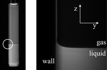 | ||
| Fig. 1 The left image is a photograph of a phase separated mixture of fluorescently labelled poly(methylmethacrylate) colloids (PMMA, σc = 50 nm) and poly(styrene) polymer (molecular weight Mw = 233 kg mol−1) in decalin, which has been taken under UV-light. The very sharp interface can be clearly seen. The image on the right is a “blow-up” of the encircled region by means of laser scanning confocal microscopy or LSCM (dimensions 350 µm by 350 µm).12 | ||
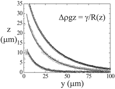 | ||
| Fig. 2 Interface from LSCM images as in Fig. 1 for three different statepoints approaching the critical point from top to bottom curve (symbols). The full curves follow from the balance between Laplace and hydrostatic pressure, i.e. solving the differential equation displayed in the figure with R(z) the radius of curvature at height z.12 | ||
3. Waves
At rest, the free interface between any two fluids, like that between a liquid and its vapour, appears to be smooth. Yet thermal motion inevitably gives rise to statistical fluctuations of the local interface position and hence leads to a rough interface. This phenomenon was first predicted almost a century ago by von Smoluchowski14 and it was Mandelstam15 who quantitatively described the interface roughness in terms of thermally excited capillary waves. These capillary waves have been studied with light and X-ray scattering and play a significant role in modern theories of interfaces (see for example ref. 16 and references therein).Solely by strongly decreasing the interfacial tension several characteristic properties of the thermal capillary waves change. The typical amplitude of the interface roughness is given by the thermal length

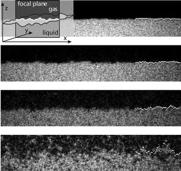 | ||
| Fig. 3 Capillary waves at the free liquid–gas interface in a phase separated colloid–polymer mixture imaged with LSCM at four different statepoints approaching the critical point from top to bottom. Here, we use a similar system as described in the caption of Fig. 1, but with σc = 142 nm and Mw = 2000 kg mol−1. The focal (viewing) plane is perpendicular to the interface and only a very thin slice is imaged (see the inset). The size of each image is 17.5 µm times 85 µm. Thermally excited capillary waves corrugate the interface and their amplitude increases upon approaching the critical point. The bright dots at the right indicate the location of the surface.13 | ||
Surprisingly, it turns out that experimental results for static and dynamic correlation functions validate the capillary wave model down to almost the particle level. This can for example be seen from the agreement between the experimentally determined dynamic height–height correlation functions and their theoretical description based on the interfacial tension and the decay time of the waves, as shown in Fig. 4. Interestingly, following only the height of a single point at the interface as a function of time allows determining such quantities, where the lowest interfacial tension found is even below the nN m−1 level.
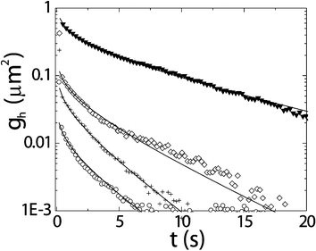 | ||
| Fig. 4 Dynamic height–height correlation functions characterising the free liquid–gas interface as obtained from quantitative analysis of LSCM pictures as in Fig. 3 approaching the critical point from the bottom to the top curve. Experimental results (symbols) are compared with predictions from the capillary wave model (lines). In this model the input only comes from macroscopic quantities such as the interfacial tension, the density difference and the viscosity, but it clearly describes the microscopic data accurately.13 | ||
4. Droplets
We study the coalescence of a drop with its bulk phase, see the images in Fig. 5. The process takes place in three consecutive stages: (i) drainage of the continuous film between droplet and bulk phase, (ii) breakup of the film, and (iii) the growth of the connection. We observe that drainage becomes very slow and eventually the breakup of the film is induced by thermal capillary waves.13 The waiting time for a certain height fluctuation, which turns out to be an important parameter for the kinetics of the process, can be directly obtained from experiment. During the third stage we observe that the radius of the connecting neck grows linearly with time both for gas bubbles and liquid droplets with an order of magnitude that is in good agreement with the capillary velocity,18 see Fig. 6. For example, here we find that the coalescence speed is 0.3 uc for gas droplets and 0.4 uc for liquid droplets, where we take the viscosity of the droplet to calculate uc. Thus, we also observe that the more viscous liquid phase slows down the coalescence of gas droplets relatively more than vice versa. Furthermore, from the Reynolds number, which compares inertial and viscous forces, we learn that inertial forces become dominant over viscous forces at a length Lη = η2/ργ, with ρ the fluid density. This length is several meters in colloid–polymer mixtures instead of only a few nm in a molecular fluid such as water and this explains the observed linear dependence.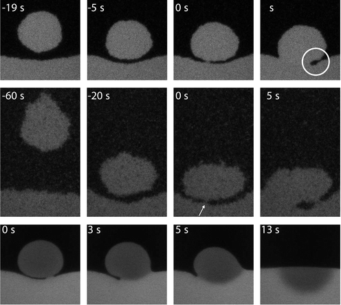 | ||
| Fig. 5 Coalescence of liquid droplets with the bulk liquid phase. Top row, the drop diameter D = 16.5 µm and the statepoint is relatively far away from the critical point; middle row, D = 21.8 µm and close to the critical point. Bottom row, D = 30 µm. The three consecutive steps of the coalescence event can be followed in time (as indicated, where t = 0 corresponds to the instant of film breakup). The white circle marks the typical shape as predicted by Eggers et al..17 In the middle row, the arrow denotes the place of film breakup. In this case, a second connection is made and gas phase is being trapped in the liquid phase. In the bottom row, the dye inside the droplet is bleached and the coalescence event can be followed in great detail. The drop forms a hemisphere in the bulk phase and spreads by diffusion.13,18 | ||
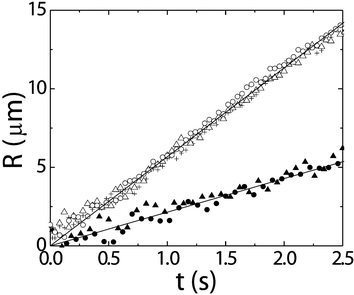 | ||
| Fig. 6 The time evolution of the radius R of the neck in a colloid–polymer mixture for gas droplets (open symbols; three different events with initial diameters of D = 32, 34 and 36 µm) and liquid droplets (closed symbols; two different events with D = 30 and 34 µm). Full curves are linear fits to the data.18 | ||
By bleaching the dye inside the liquid droplet with intense laser light, it becomes possible to study stages (ii) and (iii) in more detail and from the bottom row of images in Fig. 5 we learn that the crucial fluctuation is initiated from the bulk. We further see how the surface energy is transformed into kinetic energy upon coalescence.
In these systems it is also possible to study the formation of droplets, the opposite of the process described above. During the final stages of phase separation liquid drops nucleate e.g. at the air–dispersion interface and subsequently drip down, offering a nice opportunity to study drop snap-off in a controlled manner. Fig. 7a shows an event in a colloid–polymer mixture with a relatively high interfacial tension (∼1 µN m−1). At the point of snap-off the shape of the neck is asymmetric with a thin filament and an almost spherical drop. After breakup many satellite droplets form. Such features are also observed in the viscous snap-off of molecular liquids. However, the situation changes drastically in a mixture with a very low interfacial tension (∼20 nN m−1), see Fig. 7b, where the thermal roughness is much more pronounced and can be directly seen in the images. First experiments show that the neck shape at snap-off is more symmetric and the number of crests and troughs at the filament typically increases. Furthermore, hardly any satellite drops are being formed. This is in qualitative agreement with simulations19 and theory,20 where the effects of thermal noise on the hydrodynamic description of drop snap-off are explicitly taken into account. We are currently studying the qualitative and quantitative consequences of thermal noise on this phenomenon in greater detail.21
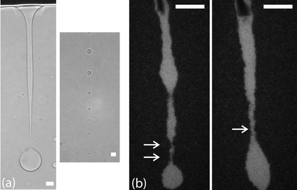 | ||
| Fig. 7 Droplet snap-off in a system with a relatively high (a) and a very low (b) interfacial tension. In the transmission light microscopy images of (a) the neck shape is highly asymmetric and many satellite drops are formed. In (b), showing two different events, the neck shapes are rather different than in (a). Only two and zero satellite droplets will form, respectively. In the top of the image the glass stick can be seen, which acts as a collector of liquid material and facilitates the snap-off. In all images scale bars denote 20 µm. | ||
5. Conclusion and outlook
We have shown that in colloid–polymer mixtures the interfacial tension is ultralow. As a sole consequence of this ultralow interfacial tension characteristic length- and timescales are strongly affected and may either increase or decrease. The capillary length decreases down to (tens of) microns; the thermal length, however, increases and may become of the order of (sub)microns. The typical interface velocity decreases and becomes only a few microns per second, in its turn leading to slow decay times. Finally, inertial terms only become important at large length- and timescales such that “life at ultralow interfacial tension” is similar to life at low Reynolds number.22By means of LSCM the consequences of this ultralow interfacial tension can be studied on wetting, waves and droplets, practically in a single experiment. We believe that the present work opens up a wide range of possibilities, e.g. to study temperature gradients and mass transport across the interface at the scale of the thermal roughness, to explore the effects of thermal noise on wetting behaviour, and on hydrodynamic instabilities and interfacial motion in micro- or nanofluidic devices, to study the freezing of capillary waves at the gel-line, to analyse the local tilt angle distribution of the interface,23,24etc.
Acknowledgements
It is a pleasure to thank Prof. Henk Lekkerkerker for his inspiring guidance during my PhD research.References
- J. S. Rowlinson and B. Widom, Molecular theory of capillarity, Clarendon Press, Oxford, 1982 Search PubMed.
- Adding surfactants may decrease the interfacial tension of molecular fluid interfaces typically down to several µN m−1 (see for example ref. 25 and references therein). In colloid–polymer mixtures the interfacial tension can easily become much lower (nN m−1).
- S. Asakura and F. Oosawa, J. Chem. Phys., 1954, 22, 1255 CAS.
- A. Vrij, Pure Appl. Chem., 1976, 48, 471 CrossRef CAS.
- P. G. De Gennes, Scaling concepts in polymer physics, Cornell University Press, Ithaca, 1979 Search PubMed.
- G. A. Vliegenthart and H. N. W. Lekkerkerker, Prog. Colloid Polym. Sci., 1997, 105, 27 CrossRef CAS.
- E. H. A. de Hoog and H. N. W. Lekkerkerker, J. Phys. Chem. B, 1999, 103, 5274 CrossRef CAS.
- B. H. Chen, B. Payandeh and M. Robert, Phys. Rev. E: Stat. Phys., Plasmas, Fluids, Relat. Interdiscip. Top., 2000, 62, 2369 CrossRef CAS.
- D. G. A. L. Aarts and H. N. W. Lekkerkerker, J. Phys.: Condens. Matter, 2004, 16, S4231 CrossRef CAS.
- D. G. A. L. Aarts, R. P. A. Dullens and H. N. W. Lekkerkerker, New J. Phys., 2005, 7, 40 CrossRef.
- D. G. A. L. Aarts, J. H. van der Wiel and H. N. W. Lekkerkerker, J. Phys.: Condens. Matter, 2003, 15, S245 CrossRef CAS.
- D. G. A. L. Aarts, J. Phys. Chem. B, 2005, 109, 7407 CrossRef CAS.
- D. G. A. L. Aarts, M. Schmidt and H. N. W. Lekkerkerker, Science, 2004, 304, 847 CrossRef CAS.
- M. V. von Smoluchowski, Ann. Phys., 1908, 25, 205 Search PubMed.
- L. Mandelstam, Ann. Phys., 1913, 41, 609–624 Search PubMed.
- S. Dietrich and A. Haase, Phys. Rep., 1995, 260, 1 CrossRef CAS.
- J. Eggers, J. R. Lister and H. A. Stone, J. Fluid Mech., 1999, 401, 293 Search PubMed.
- D. G. A. L. Aarts, H. N. W. Lekkerkerker, H. Guo, G. Wegdam and D. Bonn, Phys. Rev. Lett., 2005, 95, 164503 CrossRef.
- M. Moseler and U. Landman, Science, 2000, 289, 1165 CrossRef CAS.
- J. Eggers, Phys. Rev. Lett., 2002, 89, 084502 CrossRef.
- Y. Hennequin, D. G. A. L. Aarts, J. H. van der Wiel, G. Wegdam, J. Eggers, H. N. W. Lekkerkerker and D. Bonn, 2006, submitted.
- E. M. Purcell, Am. J. Phys., 1977, 45, 3.
- K. R. Mecke and S. Dietrich, J. Chem. Phys., 2005, 123, 204723 CrossRef.
- D. G. A. L. Aarts, M. Schmidt, H. N. W. Lekkerkerker and K. R. Mecke, Adv. Solid State Phys., 2005 Search PubMed.
- M. J. Rosen, H. Wang, P. Shen and Y. Zhu, Langmuir, 2005, 21, 3749 CrossRef CAS.
Footnotes |
| † This article is based on D. G. A. L. Aarts, The interface in demixed colloid-polymer systems: Wetting, waves and droplets, PhD thesis, University of Utrecht, 2005. |
| ‡ Present address: Laboratoire de Physique Statistique, Ecole Normale Supérieure, 24, Rue Lhomond, F-75231 Paris Cedex 05, France |
| This journal is © The Royal Society of Chemistry 2007 |