
 Open Access Article
 This Open Access Article is licensed under a
 Creative Commons Attribution 3.0 Unported Licence
A large-area lithium metal–carbon nanotube film for precise contact prelithiation in lithium-ion batteries†
Chao
Wang
 *ab,
Fangzhou
Yang
a,
Wang
Wan
a,
Shihe
Wang
a,
Yongyi
Zhang
*cd,
Yunhui
Huang
*e and
Ju
Li
*b
*ab,
Fangzhou
Yang
a,
Wang
Wan
a,
Shihe
Wang
a,
Yongyi
Zhang
*cd,
Yunhui
Huang
*e and
Ju
Li
*b
aSchool of Materials Science and Engineering, Tongji University, Shanghai 201804, China. E-mail: chaow@tongji.edu.cn
bDepartment of Materials Science and Engineering and Department of Nuclear Science and Engineering, Massachusetts Institute of Technology, Cambridge, MA 02139, USA. E-mail: liju@mit.edu
cKey Laboratory of Multifunctional Nanomaterials and Smart Systems, Advanced Materials Division, Suzhou Institute of Nano-Tech and Nano-Bionics, Chinese Academy of Sciences, Suzhou 215123, China. E-mail: yyzhang2011@sinano.ac.cn
dChina and School of Nano-Tech and Nano-Bionics, University of Science and Technology of China, Hefei 230026, China
eSchool of Materials Science and Engineering, Huazhong University of Science and Technology, Wuhan 430074, China. E-mail: huangyh@hust.edu.cn
First published on 31st August 2023
Abstract
Prelithiation is a method to improve the energy density and cycle life of lithium-ion batteries, and contact prelithiation of the graphite anode using thin lithium foil is a promising technique. However, producing thin lithium foil below 5 μm is extremely challenging, making it difficult to achieve precise prelithiation with lithium metal. Additionally, pure thin Li foil suffers from drawbacks such as low lithium utilization, debris formation, and scalability issues. To address these challenges, we developed a straightforward doctor blade method to cast molten lithium onto a carbon nanotube (CNT) film, resulting in a thin and ultra-light Li-CNT film. The increasing lithiophilicity of the CNT film induced by lithiation enables the uniform casting of molten lithium onto its surface. The method enables adjustable lithium capacities ranging from 0.1 to 1.12 mA h cm−2 or higher by controlling the amount of cast lithium. The Li-CNT films show high specific capacities and nearly 100% lithium utilization owing to their exceptional conductive network, porous structure, and electrolyte-philic nature, which facilitates the efficient transport of both electrons and lithium ions. To achieve prelithiation of the graphite anode when paired with commercial LFP electrodes of ∼3.3 mA h cm−2, our Li-CNT film significantly enhances the initial Coulombic efficiency of the LFP||Gr full cell from 89% to 100%, fully compensating for the initial loss of active lithium ions caused by solid electrolyte interface formation. Furthermore, the Li-CNT film has superior mechanical properties, positioning it as a viable candidate for practical applications in lithium-ion batteries.
Broader contextPrelithiation using a thin lithium-metal film is crucial for enhancing battery energy density by compensating for the initial lithium loss. However, precise prelithiation poses challenges as achieving an optimal amount of a few-micron thick Li-metal film, both mechanically robust and at a large scale, has been problematic. To overcome this, we developed an ultrathin Li-CNT film using a facile doctor blade process. The lithiophilic properties induced by lithiation allowed for uniform casting of molten lithium onto the CNT film's surface, resulting in a thin, lightweight Li-CNT film. This method enables adjustable lithium capacities ranging from 0.1 to 1.12 mA h cm−2 or higher. The resulting film exhibits excellent specific capacity and nearly 100% lithium utilization due to its conductive CNT network, porous structure, and electrolyte-philic properties. When paired with commercial LFP electrodes, our Li-CNT film significantly enhances full-cell energy density approximately 10% in the first cycle and 20% after 100 cycles. Moreover, the Li-CNT film demonstrates superior mechanical properties compared to pure lithium films, making it a promising candidate for practical industrial applications. Overall, our work provides valuable insights into the design and fabrication of large-area thin lithium films for efficient contact prelithiation, potentially accelerating the commercialization of anode prelithiation. |
Introduction
Lithium-ion batteries are crucial for sustainable development and have found widespread use in large-scale energy storage and electric vehicles.1,2 However, commercialized full cells with the graphite anode and cathodes such as lithium-ion phosphate (LFP), lithium cobalt oxide (LCO), and lithium nickel cobalt manganese oxide (NCM) have almost reached their limit in energy density.3–5 New systems based on lithium metal anodes are not yet practical,6 and existing mature battery systems, such as LFP-graphite and LCO-graphite, have a low initial coulombic efficiency (ICE), of less than 90%.7 When paired with silicon-based anodes, the ICE is even lower, at around 80%, leading to a 20% decrease in the energy density of the battery system at the pack level.8 The loss of active lithium in the first cycle is mainly caused by the solid electrolyte interface (SEI) formation at the anode surface.9 The initial depletion of active lithium results in a substantial reduction in the energy density. To address this issue, extensive research has focused on utilizing lithium sacrificial agents that can offset the initial active lithium loss. One effective solution is prelithiation, which compensates for this loss of active lithium inventory. Among the various options, lithium metal anodes offer the highest energy density and serve as the most efficient prelithiation agents for lithium-ion batteries.10–12 However, the initial lithium compensation amount should be appropriate and precise to avoid problems such as lithium metal dendrite and low coulombic efficiency. A precise prelithiation method is of great importance, as over-prelithiation can lead to long-term side reactions between the electrolyte and the residual lithium metal, causing more problems, while under-prelithiation will not provide a noticeable improvement.Precise prelithiation using lithium metal is difficult to achieve. The areal capacity of a commercial lithium-ion battery is around 3–4 mA h cm−2. Assuming an ICE of less than 90%, the prelithiation amount should be less than 0.5 mA h cm−2. Lithium metal has the highest specific capacity of 3860 mA h g−1, so the use of lithium metal needs to be less than 0.13 mg cm−2 or 2.5 μm in average thickness or less. For some high-power cases, the areal capacity will be even lower. To supplement a lithium amount of 0.3–0.4 mA h cm−2, only 1.5–2 μm (0.08–0.11 mg cm−2) average lithium thickness is needed.
Extensive studies have been done on the particle size reduction and thinning of lithium metal. Stabilized lithium metal powder (SLMP), which is coated by a protective layer such as Li2CO3, was developed by FMC Corporation more than ten years ago.13 It was added to the anode slurry. The SLMP needs to be activated by pressure, which causes the protective layer to break and expose Li metal, enabling electrical contact between lithium and active materials in the anode to achieve SLMP prelithiation. However, the utilization of lithium is low by using SLMP. Gao et al. developed a uniformly dispersed SLMP suspension for anode prelithiation, and the lithium efficiency is around 50%.14
The other way is to use lithium metal foil as the prelithiation agent. The difficulty lies in the reduction of the lithium foil thickness. Chen et al. developed an ultrathin lithium metal-graphene oxide host foil (Li@eGF) with a controllable thickness of as thin as 0.5 μm, made through a molten lithium infiltration method at 350 °C.11 Such a method using a stacked graphene layer as the host is challenging to scale up, and a large amount of oxygen-containing functional groups in the graphene will consume some lithium. Zhang et al. developed a vacuum thermal evaporation method to deposit lithium on the anode surface.15 A rolling process was followed to decrease the porosity of the lithium film to form confocal contact with the electrode. The lithium utilization of the vacuum thermal evaporated lithium can reach 91%, an improvement of 17% compared to the one using mechanical rolling. The high lithium utilization is due to the conformal contact with abundant electron channels between lithium and the anode electrode. The utilization here is defined by the specific capacity of the lithium films but not the one using the lithium provided/needed for the full cell. Moreover, the sticking problem of lithium foil during the high-pressure rolling process is troublesome,16 and lithium vapor is dangerous.
Here, we developed a facile doctor blade method to cast the molten lithium liquid on a thin, light carbon nanotube (CNT) film without pressing. The CNT film was chosen as the substrate due to its excellent mechanical properties, good electronic conductivity, and light weight. The interconnected carbon nanotube network and the porous nature of the CNT film can efficiently transport electrons and lithium ions. Lithium loading on the CNT film, as Li-CNT films, is controllable and can be as low as 0.1 mg cm−2. The specific capacities of the Li-CNT films for commercial electrodes are above 1200 mA h g−1. Thanks to the excellent conductive CNT network and good electrolyte wetting ability, the utilization of lithium can reach almost 100%. The utilization is calculated by the lithium provided/lithium needed in actual full-cell cycling. When using the thin Li-CNT film as a prelithiation agent, as depicted in Fig. 1a, the ICE reaches the same level as the LFP half-cell with a lithium metal anode. This indicates complete compensation for the initial active lithium-ion loss caused by the SEI. The energy density of LFP||Gr full cells increases by 10% in the first cycle and 20% after 100 cycles. However, achieving a similar level of energy density improvement by enhancing the anode materials is quite challenging.
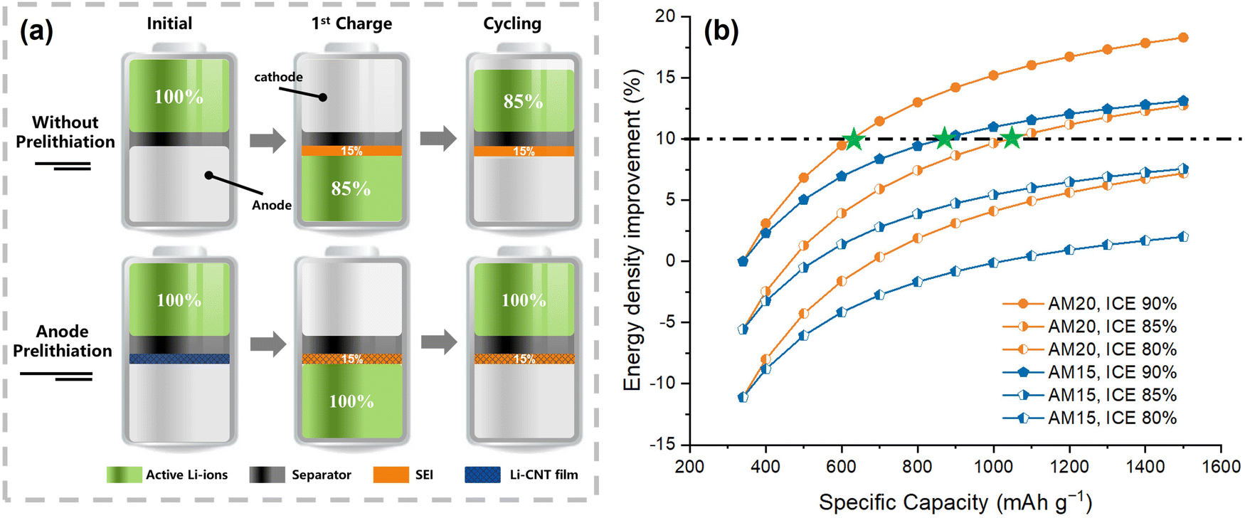 | ||
| Fig. 1 (a) Scheme of the active Li-ion loss for full cells without and with Li-CNT film prelithiation. (b) Relationship of specific capacity and energy density improvement of the LFP||Gr pack level based on different anode mass ratios and ICE. | ||
Based on Fig. 1b for the LFP||Gr system, when the anode mass is fixed at 15%, and the ICE is set to 90% (AM 15, ICE 90), doubling the specific capacity of the anode can lead to a reduction in the anode mass ratio to 7.5%, resulting in an approximately 8% increase in energy density. However, achieving this improvement is not an easy feat. Increasing the specific capacity of the anode without impacting the cycling performance or sacrificing ICE is a daunting challenge. For instance, lowering the ICE to 85% with higher anode material percentage at 20% (AM 20, ICE 85) would require at least a three-fold increase in the specific capacity of the anode materials to achieve a similar level of improvement. Even if the specific capacity of anode materials increases to 1500 mA h g−1, an anode with an ICE of only 80% (AM 15, ICE 80) would yield a meager 0.55% improvement in energy density. The ESI† contains more details on the calculations. Hence, it is worth considering that prelithiation can offer a significant improvement in the energy density for full cells compared to the development of new anode materials. Moreover, the tensile strength and Young's modulus of the Li-CNT film are much higher than those of pure lithium film. Good mechanical properties and facile fabrication bode well for its practical application.
Results and discussion
The fabrication process of Li-CNT films involved the production of CNT films using the floating catalytic chemical vapor deposition method with a meter-level area and a thickness of 1–5 μm.17 These CNT films have already been produced on a large scale and are used as fabric materials for functional cloth.18 Fig. S1 (ESI†) shows a photograph of the CNT film obtained, with an area of around 1 m2. The weight of the 2 μm film is approximately 0.1 mg cm−2, and it has a porosity of 70%, thus minimizing inefficient weight gain for the CNT-Li and facilitating electrolyte penetration. Although several studies have used CNT or carbon fiber-based substrates to make a lithium-metal composite, the substrates are typically too heavy or thick.19–22 Such a heavy substrate greatly dilutes the energy density of lithium. Therefore, the ultra-light and thin CNT film with excellent mechanical properties in tension is crucial.Fig. 2a illustrates the steps of the fabrication process for a Li-CNT film. However, when it was lithiated for a few seconds, it became lithiophilic. The lithiation process only took a few seconds, resulting in a color change from black to deep blue, as observed during the molten lithium coating process (Fig. S2, ESI†). Subsequently, molten lithium was uniformly cast onto the CNT film. The resulting Li-CNT film was then placed on a cold stainless-steel plate to cool down rapidly and prevent potential side reactions of lithium at high temperatures. The photographs of the Li-CNT film, which had a size of around 50 cm2, and was robust and flexible, are presented in Fig. 2b and c. The film remained intact even after being freely folded and rotated (Fig. 2d). Fig. 2e shows the XRD pattern of the CNT film before and after loading lithium. The Li-CNT film was sealed in a thin Kapton film to inhibit oxidation. Since the thin film samples lacked good crystallization, the XRD peak intensities are weak. The CNT film exhibited a typical carbon peak at around 2θ = 26°. In contrast, the XRD pattern of Li-CNT film revealed obvious main peaks that were attributed to the (110) and (200) planes of BCC lithium metal and a leftward shift of the carbon peak due to lithiation, indicating the successful loading and intercalation of lithium into multiwalled CNTs. The highest peak of the LiC12 phase was attributed to the lithiated CNT film, which was consistent with the observed deep blue color.23
 | ||
| Fig. 2 (a) Scheme of the fabrication process for Li-CNT film. (b)–(d) Photographs of the Li-CNT film, including images of the film rotating and recovering its shape after being deformed. (e) XRD patterns for Li-CNT film, pure CNT film, and Kapton tape. (f) Tensile stress–strain curves of the pure CNT film, Li-CNT film, and pure Li film. (g) Surface contact angle image of the EC/DMC-based electrolyte on the CNT film. | ||
The CNT film demonstrated remarkable mechanical strength. As shown in the stress–strain curves in Fig. 2f, the film exhibited a tensile strength of 64 MPa and an elastic modulus of 2254 MPa. Upon loading of Li, the tensile strength decreased to 41.4 MPa while the elastic modulus decreased to 1991 MPa. The decrease may be caused by the lithiation of CNT films. However, even after loading lithium, the mechanical strength of the Li-CNT film remained significantly better than that of the pure lithium metal film, which only has a tensile strength of 1.15 MPa and Young's modulus of 104 MPa (Fig. S3, ESI†). Such improved mechanical strength is crucial for the practical application of the ultrathin electrode. Fig. 2g shows the wettability of the liquid electrolyte (1 M LiPF6 in EC![[thin space (1/6-em)]](https://www.rsc.org/images/entities/char_2009.gif) :DMC = 3:7 vol% with 2% VC) to the CNT film, with a measured static contact angle of around 37°, indicating that the surface can be easily wetted by the electrolyte. Additionally, the porous nature of the CNT film allows for the efficient infiltration of electrolytes.
:DMC = 3:7 vol% with 2% VC) to the CNT film, with a measured static contact angle of around 37°, indicating that the surface can be easily wetted by the electrolyte. Additionally, the porous nature of the CNT film allows for the efficient infiltration of electrolytes.
The morphology and cross-section of the CNT and Li-CNT films, which were cut by a focused ion beam (FIB), are shown in Fig. 3. A CNT film with a thickness of 2 μm was chosen as the substrate because it exhibited good strength and a light weight of 0.15 mg cm−2. The thinner films can also be used, but they would be prone to breakage during lithium coating, while thicker ones would introduce more weight and reduce energy density. Fig. 3a shows the cross-section of the 2 μm CNT film, which became thicker due to damage during the FIB cutting process. Fig. 3f shows a cross-section image cut with scissors, where the CNT nanotubes are much thinner. Fig. 3e and g are top views of the CNT film, illustrating the interconnection of numerous CNTs and its porosity. After lithium loading, the CNTs became slightly thicker due to lithiation. A series of Li-CNT films with different thicknesses were obtained by changing the lithium loading during the hot molten lithium casting process. Here, we demonstrate cross-section images with lithium layer thicknesses of 1.5 μm (Fig. 3b), 2.5 μm (Fig. 3c), and 5 μm (Fig. 3d). The obtained lithium composite film can be as thin as 670 nm (Fig. S4, ESI†). The surface of the Li-CNT film is flat; at high magnification, some nanoparticles can be seen, which are likely caused by lithium oxidation during the molten lithium coating process and sample transfer process. Moisture, oxygen, and nitrogen in the glovebox are also non-negligible factors. Fig. 3i shows the SEM image of the Li-CNT film after Li stripping, where the CNT fibers are clearly visible, and the oxidation-product nanoparticles remain on the film.
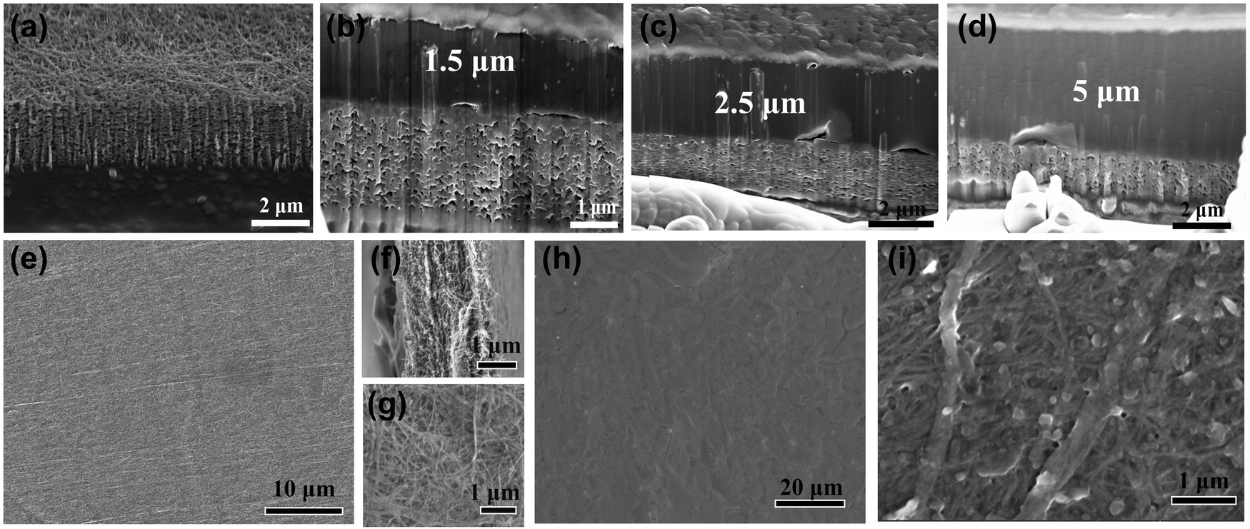 | ||
| Fig. 3 SEM images of the CNT and Li-CNT film. Cross-section SEM image after focused ion beam cutting: (a) pure CNT film, Li-CNT film with different lithium thicknesses (b) 1.5, (c) 2.5, (d) 5 μm. Top-view SEM of CNT film at different magnifications (e) and (g). Cross-section image of CNT film cut using scissors without the damage to the e-beam (f). Top-view SEM image of Li-CNT film and the one after delithiation (h) and (i). | ||
Controlling the lithium capacity of the prelithation agent is crucial for achieving precise lithium supplementation. While it may be easy to produce a thick lithium film with high capacity, obtaining a low lithium capacity, such as less than 1 mA h cm−2, can be challenging. Herewith, using the Li-CNT film as an electrode enables achieving a range of lithium extraction capacities, as demonstrated in Fig. 4a, with areal capacities ranging from 0.11, 0.24, 0.36, 0.48, 0.64, 0.84 mA h cm−2. The electrodes are measured by weight, which is a more accurate method than measuring by thickness since the thin film is difficult to flatten and be measured consistently.
 | ||
| Fig. 4 Electrochemical performance of the Li-CNT films. (a) Lithium stripping curves of Li-CNT films charged to 1 V vs. Li/Li+ with a series areal capacity. (b) Specific capacity of Li-CNT films with different weights. (c) Galvanostatic charge and discharge curves of the Li-CNT film at 1st and 50th cycles at 0.36 mA cm−2, which is 0.1C of the LFP electrode. (d) Galvanostatic cycling capacity and Coulombic efficiency of Li-CNT film at 0.33 mA cm−2. The counter-electrode is Li-metal foil in the above tests. | ||
Moreover, the Li-CNT film exhibits a specific capacity of 550 mA h g−1 at a weight of 0.2 mg cm−2. With a weight of 0.35 mg cm−2, the areal capacity can reach 0.48 mA h cm−2, corresponding to a specific capacity of 1371 mA h g−1 (Fig. 4b) in half-cell versus Li metal foil. When the loading is increased to 0.62 mg cm−2, the areal capacity can reach 1.12 mA h cm−2, with a specific capacity of 1806.4 mA h g−1 (Fig. S5, ESI†) in delithiation. The higher the weight, the higher the specific capacity, as the weight percentage of the CNT substrate is lower. Also, the capacity is affected by the side reaction of lithium in the glove box. Although the atmosphere is well-controlled in the glove box, oxygen, nitrogen, or water may still be present. Lithium is much more reactive at high temperatures than at room temperature, and oxidation can occur rapidly on the surface of the lithium.
Fig. 4c illustrates the charge and discharge curves of the Li-CNT film for the 1st and 50th cycles at a constant current density of 0.33 mA cm−2 in a half-cell. The Li-CNT film, with a weight of 0.3 mg cm−2, initially extracts approximately 0.36 mA h cm−2 of lithium, and the voltage is comparable to that of lithium metal stripping. Subsequently, the CNT film exhibits a low lithiation capacity, with a discharge capacity of less than 0.015 mA h cm−2. Fig. 4d displays the cycling performance after delithiation, showing that the delithiated Li-CNT film has a cycling capacity of approximately 0.012 mA h. Due to its small capacity, the influence of the CNT film is negligible for the full cell with an LFP electrode's high areal capacity of 3.3 mA h cm−2. However, owing to the ultralight weight of the CNT film, its areal capacity is 4‰ of the electrode capacity. The average Coulombic efficiency of the CNT film is more than 99.5%, and its lithium consumption accounts for only ten in a million level of the total lithium quantity. Under a current density of 0.33 mA cm−2, which is a very high rate for CNT, the capacity of CNT film is fair to low. However, the CNT films demonstrate significantly different electrochemical performance at a low current rate of 100 mA g−1, exhibiting a specific capacity of approximately 500 mA h g−1, according to Fig. S6 (ESI†). Following the chemical lithiation of lithium at high temperatures and high current density delithiation, some lithium remains intercalated in the CNT.
The contact prelithiation process of the graphite electrode with Li-CNT film is a rapid and effective method for enhancing the initial capacity of the electrode. The cell was assembled and immediately tested to monitor the open circuit potential (OCP) evolution. As shown in Fig. 5a, the initial voltage was approximately 0.27 V and remained stable for 24 hours, gradually increasing by 0.1 V. Typically, the OCP of a graphite half-cell is around 3.2 V (Fig. 5b), but the prelithiation process with Li-CNT film resulted in a decrease in the initial OCP due to the lithiation of the graphite electrode. The subsequent increase in voltage is attributed to lithium diffusion in the bulk graphite, which was derived from concentration polarization. The first cycle's charge and discharge capacities of the graphite anode were 357.2 mA h g−1 and 405.9 mA h g−1, respectively, indicating an ICE of 88%. After lithiation with the Li-CNT film, the initial discharging capacity decreased to 353.3 mA h g−1, while the charging capacity remained almost the same as the blank graphite anode, resulting in an improved ICE of 100.4%. Through the graphite half-cell analysis, we can infer that the active lithium loss at the solid electrolyte interphase (SEI) formation process can be entirely compensated by the Li-CNT film.
 | ||
| Fig. 5 Electrochemical performance of the prelithiated full cells. (a) Open circuit potential change of LFP||Gr-Li-CNT full cells immediately after cell assembly. Initial galvanostatic charge and discharge curves at 0.1C (b) half cells of Gr||Li and Gr-Li-CNT||Li, (c) LFP||Li half-cell, and full cells of LFP||Gr-Li-CNT, and LFP||Gr. (d) LFP||Gr-Li-CNT and LFP||Gr cells at 0.1C. (d) Specific discharge capacity and (e) coulombic efficiency of LFP||Gr-Li-CNT and LFP||Gr full cells at 0.1C. (f) Rate performance of the lithiated LFP||Gr-Li-CNT full cells at 0.1, 0.2 and 0.3C. (g) Rate capability of the LFP||Gr-Li-CNT cells. (h) Cycling behavior of the LFP||Gr-Li-CNT cell at a 1C rate. (i) Initial galvanostatic charge and discharge profiles at 0.1C for NCM||Si, NCM||Li, and NCM||Si-Li-CNT configurations. | ||
To gain deeper insights into the prelithiation process, we conducted an in situ lithium absorption experiment on the Li-CNT film contact prelithiation of graphite electrodes. To facilitate observation, we placed the electrodes within a transparent plastic zip-lock bag, with the lithium side facing us. With applied finger pressure, the prelithiation process was accomplished within approximately 4 minutes. This procedure is visually depicted in Movie S1 (ESI†), while corresponding screenshots are provided in Fig. S7 (ESI†). As the lithium gradually diminishes, the final outcome is a uniformly black CNT film on both sides, signifying the absence of residual lithium. This uniform appearance holds true for the Gr electrode after prelithiation as well, with no traces of attached lithium observed (Fig. S8, ESI†). The morphology of the CNT film and the graphite electrode after prelithiation in a coin cell with the Li side face to Gr is depicted in Fig. S9 (ESI†), further confirming the absence of residual lithium. Additionally, X-ray diffraction (XRD) analysis of the graphite electrode post-prelithiation reveals a slight left shift in the (002) peak, indicating the successful prelithiation of the graphite material (Fig. S10, ESI†). It's important to note that the pressure within a coin cell is considerably greater and more evenly distributed than what can be manually applied by a finger, suggesting that the actual prelithiation process in the cell would be faster and uniform than demonstrated here.
The cell featuring an artificial Li-CNT film on the electrode surface exhibited a marginally elevated overpotential during the initial discharge profile compared to the unmodified graphite cell. Nevertheless, the overpotentials in subsequent charge and discharge cycles aligned closely with those of the bare graphite electrode (Fig. 5b and Fig. S11, ESI†). This phenomenon can be ascribed to the passivation of the porous film by the SEI, which facilitated efficient lithium-ion and electron conductivity. The EIS data obtained from both the Gr||Li and Gr-Li-CNT||Li cells substantiated this observation, indicating that the initial impedance of the Gr-Li-CNT||Li cell was slightly higher than that of the Gr||Li cell but decreased after a single cycle (Fig. S12a and b, ESI†). This decline was likely due to the effective electron and lithium-ion conductivities of the lithiated CNT film, which also led to a decrease in charge transfer impedance. Remarkably, the impedance of the full cells was significantly lower than that of the half cells. As seen in Fig. S12c (ESI†), the impedance outcomes of the full cells closely resembled those of the half cells, implying that the additional layer did not increase the overall impedance of the cell.
Fig. 5c displays the electrochemical performance of the LFP||Li half-cell and LFP||Gr full-cell. All the cells were tested using a high loading (21–22 mg cm−2) commercial LFP electrode source from China Shoto Ltd, with an area capacity of 3.3 mA h cm−2. To prelithiate the LFP electrodes, a Li-CNT film weighing approximately 0.3 mg cm−2 was employed, with an N/P ratio of ∼1.15. The LFP||Gr cell exhibited an initial discharge capacity of ∼142 mA h g−1 and an ICE of 89%, resulting in an initial active lithium loss of around 0.36 mA h cm−2. In contrast, the LFP||Gr CNT-Li full cells demonstrated significantly improved electrochemical performance. The Coulombic efficiency of the LFP||Gr-Li-CNT cell discharged to 2.5 V is 98.4%, which increased to 100% when discharged to 2 V with constant discharge voltage (Fig. S13, ESI†). After prelithiation, the ICE of the LFP||Gr-Li-CNT cell matched that of the LFP||Li half-cell, indicating 100% non-active lithium compensation in the first cycle. LFP||Gr-Li-CNT cell displayed an initial discharge capacity of ∼160 mA h g−1, equivalent to that of the LFP||Li cell (Fig. 5c).
When operating at slow rates, issues with side reactions and Coulombic efficiency are more prominent. As depicted in Fig. 5d, the cycling performance of LFP||Gr and LFP||Gr-Li-CNT cells at 0.1C rate show a substantial enhancement in energy density after prelithiation, with a capacity retention of 94.6% after 100 cycles, leading to a 20% increase in the energy density compared to the control group. Taking into account the mass of Li-CNT film, the energy density improves by approximately 10%. In a typical commercial cell, the mass ratio of the anode electrode is around 12%, and the mass of the anode is 12 mg cm−2. The mass of the prelithiation agent is 0.3 mg cm−2, equivalent to approximately 2.5% of the anode material and 3‰ of the total cell mass. The improvement of energy capacity by about 11% results in an overall increase in mass energy density of around 11%/(1 + 3‰) = 10.97%, which is significant compared to the rise of active materials. As previously discussed in Fig. 1b, to attain the same energy density improvement, the specific capacity of the anode must be increased to at least 900 mA h g−1. However, achieving a specific capacity of 900 mA h g−1 with 90% ICE is challenging.
Fig. 5e displays the coulombic efficiency of LFP||Gr and LFP||Gr-Li-CNT cells during cycling. The prelithiated cells showed an average CE above 99.9%, surpassing that of the blank LFP||Gr cell. The improved CE suggests that the incorporation of the CNT film in the full cells did not introduce any side effects that would consume active lithium ions during cycling. The relationship between the Coulombic efficiency and cycling life is demonstrated in Fig. S14 (ESI†), with the data based on the assumption that the loss of active lithium ions is responsible for CE reduction. This suggests that even a marginal 0.1% difference can significantly impact cycling performance in a full cell with limited lithium. The rate performance of the LFP||Gr-Li-CNT cell is shown in Fig. 5f, which was conducted at 0.1 to 0.3C using the thick LFP (3.3 mA cm−2) and graphite electrodes. The full cell displayed discharge capacities of 159.3, 156.1, and 152.3 mA h g−1 at 0.1, 0.2, and 0.3C, and after 84 cycles, it could recover to 154.6 mA h g−1 at 0.2C. However, higher-rate performance cannot be adequately tested in our labs using such a high loading LFP electrode. For higher-rate evaluations, we utilized self-manufactured LFP electrodes with reduced loading. The prelithiated LFP||Gr-Li-CNT cells exhibit a favorable rate capability and cycling stability at 1C, as illustrated in Fig. 5g and h. Notably, discharge capacities of 136.5 mA h g−1 at 1C and 120.6 mA h g−1 at 2C were achieved, accompanied by an impressive capacity retention of 99% over 100 cycles at 1C. The corresponding CE 1C is illustrated in Fig. S15 (ESI†), and it consistently surpasses 99.9%. The visual representation and morphological examination of the CNT films within the LFP||Gr-Li-CNT cells following 100 cycles at 1C, along with the rate performance, can be observed in Fig. S16 (ESI†). Impressively, no detectable lithium dendrites were observed on the surface of the CNT film. Furthermore, it's noteworthy that we observed a substantial decline in the conductivity of the CNT film, from 5 × 10³ S m−1 to 4 S m−1, subsequent to prelithiation and cycling within the battery. This reduction in conductivity has contributed to a decreased tendency for lithium deposition on the CNT film.
Furthermore, we extended the application of the Li-CNT film to prelithiate the LiNi0.8Co0.1Mn0.1O2 (NCM)||Si system. In the NCM||Si full cell, the ICE is approximately 78%, consistent with the silicon's initial CE of 79.2% at 0.1C (Fig. S17, ESI†). After prelithiation, the NCM||Si-Li-CNT full cell exhibits a notably improved ICE of approximately 88%, which is comparable to the ICE of the NCM||Li half cell at 90% (Fig. 5i). Remarkably, the prelithiated NCM||Si-Li-CNT cell exhibits vastly improved cycling performance compared to the unprelithiated NCM||Si cell (Fig. S18, ESI†). This improvement could be attributed to the role of the lithiated CNT film as a buffer layer for volume expansion within the silicon anode, ultimately enhancing the stability of the Si anode.11
After prelithation, we did not observe any residual lithium on the electrode surface or CNT film c. However, when we used thin lithium metal foil as the prelithiation agent, we consistently observed pulverized lithium on the electrode surface (Fig. S20, ESI†). Furthermore, pure lithium foil or alloy foil is difficult to thin down to less than 5 μm, and even at a thickness of 5 μm, it introduces more lithium than needed, making precise prelithiation challenging. The schematic diagram of the contact prelithiation process of Li foil and Li-CNT foil is shown in Fig. 6a and b. In the presence of an electrolyte, the Li redox reaction occurs at the place where both electrons and lithium ions can flow. Once the reaction takes place, graphite gets lithiated, and lithium foil will be consumed from the contact place. After lithium consumption at the contact place, it will lose its electronic pathway, and the oxidation–reduction reaction cannot occur, resulting in some residual lithium metal being generated on the graphite surface. However, when CNT film is used as the substrate, the interconnected porous CNT network provides excellent electron conductivity, and the electronic pathway is always maintained. Additionally, the porous CNT film can adsorb electrolytes, making the prelithiation process of Li-CNT film much faster than lithium foil. The good electronic and lithium-ion conductivities of CNT film provide optimal conditions for fast and uniform lithiation with high lithium utilization.
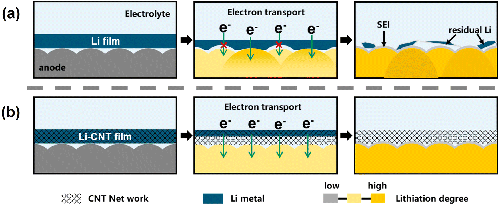 | ||
| Fig. 6 Schematic diagram of the contact prelithiation process of (a) Li foil, and (b) Li-CNT foil. | ||
Conclusions
In summary, we have developed a facile method to cast molten lithium onto a lightweight carbon nanotube (CNT) film for fabricating ultra-light, robust Li-CNT films for precise prelithiation. The CNT film substrate's lightweight and thinness, combined with its lithiophilic properties induced by lithiation, enabled uniform casting of molten lithium on the film, resulting in a flexible and strong Li-CNT film. This method allows us to control the weight and thickness of the films by varying the amount of molten lithium used. Furthermore, the CNT film's excellent mechanical properties ensure that the Li-CNT film retains good mechanical strength, significantly better than a pure lithium metal film. This suggests that the CNT film could be a promising material for ultra-thin electrodes. The Li-CNT film also demonstrated high lithium loading capacity and reversible lithium stripping, achieving areal capacities ranging from 0.1 to 1.12 mA h cm−2, with the potential for higher capacities. A 0.3 mg cm−2 Li-CNT film shows an impressive specific capacity of ∼1200 mA h g−1, which can couple well with a commercial LFP electrode with an areal capacity of ∼3.6 mA h cm−2. When used for prelithiation, the highly electrophilic CNT film substrate provides a favorable electron and lithium-ion transport environment, resulting in high lithium utilization and complete compensation for initial active lithium loss.Full cells using LFP||Gr achieved an ICE of ∼100%, indicating high efficiency. This technique has significantly improved the energy density of lithium-ion batteries, with LFP||Gr full cells showing an 11% increase in energy density. Using Li-CNT films for contact prelithiation eliminates the need for high-pressure rolling, which is required when using direct vacuum lithium sputtering on graphite anodes. Additionally, the lithiated CNT film has the potential to serve as a buffer layer of volume expansion for anode materials such as silicon, potentially improving the electrochemical performance. Nevertheless, the Li-CNT films’ susceptibility to moisture and oxygen poses a challenge to their commercial viability, prompting us to actively seek strategies to enhance their stability. We remain resolute in our belief that the CNT film itself holds considerable promise as a lithium supporter for the production of Li-CNT films, effectively serving as prelithiation agents. Our commitment is underscored by our ongoing exploration of diverse techniques and meticulous refinement of production parameters, all geared toward enabling the realization of larger-scale and remarkably efficient manufacturing processes for Li-CNT films. Within this context, lithium vacuum thermal evaporation and electrochemical deposition24 stand out as promising alternatives, each holding the potential to achieve larger scales.
Experimental
Li-CNT film fabrication
The Li-CNT film fabrication process was carried out inside an argon-filled glovebox. First, a CNT film was attached to a 316 stainless-steel plate using Kapton tape. The stainless-steel plate was then put on a hot plate under 250 °C. After the plate was heated, a certain amount of lithium was put on the surface of the CNT film. A stainless-steel triangle cell spreader was used to coat the lithium on the CNT film. The spreader must be heated to a high temperature to ensure the molten lithium will not be cooled down upon contact. The CNT film was lithiated from a lithophilic surface during the coating process before the spreader was used to apply the molten lithium. After coating, the stainless-steel plate was immediately transferred to a stainless-steel floor for rapid cooling to minimize side reactions, as the reactivity of metal lithium increases significantly at high temperatures. The Li-CNT film was wrapped with a separator to prevent metal lithium from sticking to the pouch tools during pouching.Electrode preparation
The commercially obtained signal-side LFP cathode electrodes were supplied by China Shoto Ltd. These electrodes featured a substantial active material loading of 21–22 mg cm−2 and an area capacity of approximately ∼3.3 mA h cm−2, with an impressive active materials ratio of 95% within the electrode. Graphite electrodes were prepared by mixing the graphite powder (Dodochem) with Super P conductive carbon black (TIMCAL) and polyvinylidene fluoride (PVDF 6020, Solvay) in a weight ratio of 90:5:5 using N-methyl pyrrolidone (NMP) as the solvent. The resulting slurry was then cast on a Cu foil with a thickness of 400 μm to achieve a graphite loading of about 11 mg cm−2. After being subjected to a drying temperature of 80 °C for 12 hours, the electrodes underwent shaping into circular disks with a diameter of 12 mm to facilitate their assembly into coin cells. Lithium metal was selected as the half-cell counter electrode with a diameter of 15 mm. In terms of rate performance assessment, a reduced loading LFP cathode was created using the identical slurry manufacturing process as the graphite electrode. The LFP cathode possessed an active material ratio of 80% and a loading of approximately 7 mg cm−2. Similarly, the NCM electrode was manufactured using the same procedure, featuring an active material loading of around 6 mg cm−2. For the silicon electrode (Daejoo Electronic Materials, DMSO), PAA (polyacrylic acid) was utilized as the binder, and the active material ratio was set at 80%. To match the NCM cathode, the silicon loading was approximately about 1 mg cm−2.
Cell assembly and electrochemical tests
All coin cells were assembled in an argon-filled glove box with oxygen and water content of less than 0.1 ppm. 2025-Type coin cells were fabricated using 40 μL of electrolyte (1 M LiPF6 in EC:DMC = 3:7 vol% with 2% VC) for LFP||Gr and 1 M LiPF6 EC:DMC:EMC = 1:1:1 with 10% FEC for NCM||Si, and a single piece of PP separator. The coin cells rested for 8 h to ensure electrolyte infiltration before electrochemical performance testing. For the LFP||Gr system, each cycle of the half and full-cell tests involved a constant current charging process to 3.7 V at a given rate, followed by a constant voltage charging process to one-fifth of the given rate at 3.7 V and a constant current discharging process to 2.5 V or 2 V at the same rate. In the case of NCM cells, the charging process involved applying a constant current until reaching 4.3 V, followed by discharge to 2 V in the half-cell configuration. For the full cells incorporating a silicon anode, the discharge was conducted to either 2 V or 1 V. The electrochemical performance was measured at 25 °C using a MIHW-200–160CH battery cycler (Neware). EIS measurements were conducted from 0.1 to 1 MHz with an AC voltage amplitude of 10 mV using Interface 1010E potentiostat (Gamry). For the in situ prelithiation experiments, we enhanced visibility by utilizing a transparent plastic zip-lock bag to encase the electrode, ensuring that the lithium side faced us, thus enabling clear observation. The procedure encompassed the careful alignment of the Li-CNT film onto the graphite electrode's surface. Following this, the electrolyte was introduced into the zip-lock bag, and gentle pressure was applied using my finger to initiate the prelithiation process. Movie S1 (ESI†) was edited to accelerate its speed and trim its length, and the total duration is approximately 4 minutes for the entire process.
Characteristic
SEM and cross-section images were taken by cross-sectioning a sample with a Ga+ ion beam and observing via the electron beam on a Thermo Fisher Helios CX G4 dual beam focused-ion-beam/SEM. Crystalline structures of the samples were determined via X-ray diffraction (XRD) using a parallel beam instrument (Smartlab, Rigaku, with Cu Kα with a wavelength of 1.542 Å) with preliminary sample sealing by a Kapton film inside an argon-filled glove box. Tensile strength measurements were conducted at room temperature using a microcomputer-controlled electronic universal testing machine (Lishi (Shanghai) Instruments Co., Ltd, P. R. China) equipped with a 10 N load cell at a speed of 1 mm min−1. The conductivity was assessed using a four-probe electronic conductivity tester, specifically the JGDZ-ST2258 model.Conflicts of interest
There are no conflicts to declare.Acknowledgements
CW acknowledges support from the National Key Research and Development Program of China (2022YFB3803400), the Shanghai Pujiang Program (22PJ1413400), and the Fundamental Research Funds for Central Universities. JL acknowledges support by NSF CBET-2034902.Notes and references
- M. Armand and J. M. Tarascon, Nature, 2008, 451, 652–657 CrossRef CAS PubMed.
- A. Masias, J. Marcicki and W. A. Paxton, ACS Energy Lett., 2021, 6, 621–630 CrossRef CAS.
- B. E. Murdock, K. E. Toghill and N. Tapia-Ruiz, Adv. Energy Mater., 2021, 11, 2102028 CrossRef CAS.
- H. Zhou, F. Xin, B. Pei and M. S. Whittingham, ACS Energy Lett., 2019, 4, 1902–1906 CrossRef CAS.
- A. Manthiram, Nat. Commun., 2020, 11, 1550 CrossRef CAS PubMed.
- P. G. Bruce, S. A. Freunberger, L. J. Hardwick and J.-M. Tarascon, Nat. Mater., 2012, 11, 19–29 CrossRef CAS PubMed.
- C. Zu, Y. Ren, F. Guo, H. Yu and H. Li, Adv. Sustain. Syst., 2021, 2, 2100062 CAS.
- M. C. Schulze and N. R. Neale, ACS Energy Lett., 2021, 6, 1082–1086 CrossRef CAS.
- S. J. An, J. Li, C. Daniel, D. Mohanty, S. Nagpure and D. L. Wood, Carbon, 2016, 105, 52–76 CrossRef CAS.
- Y. Sun, H.-W. Lee, Z. W. Seh, N. Liu, J. Sun, Y. Li and Y. Cui, Nat. Energy, 2016, 1, 15008 CrossRef CAS.
- H. Chen, Y. Yang, D. T. Boyle, Y. K. Jeong, R. Xu, L. S. de Vasconcelos, Z. Huang, H. Wang, H. Wang, W. Huang, H. Li, J. Wang, H. Gu, R. Matsumoto, K. Motohashi, Y. Nakayama, K. Zhao and Y. Cui, Nat. Energy, 2021, 6, 790–798 CrossRef CAS.
- F. Wang, B. Wang, J. Li, B. Wang, Y. Zhou, D. Wang, H. Liu and S. Dou, ACS Nano, 2021, 15, 2197–2218 CrossRef CAS PubMed.
- B. B. Fitch, M. Yakovleva, Y. Li, I. Plitz, A. Skrzypczak, F. Badway, G. G. Amatucci and Y. Gao, ECS Trans., 2007, 3, 15 CrossRef.
- G. Ai, Z. Wang, H. Zhao, W. Mao, Y. Fu, R. Yi, Y. Gao, V. Battaglia, D. Wang, S. Lopatin and G. Liu, J. Power Sources, 2016, 309, 33–41 CrossRef CAS.
- X.-Y. Yue, Y.-X. Yao, J. Zhang, S.-Y. Yang, Z. Li, C. Yan and Q. Zhang, Adv. Mater., 2022, 34, 2110337 CrossRef CAS PubMed.
- C. Zhang, H. Fan, X. Chen, H. Xu, J. Lou, Y. Li, Y. Huang and S. Li, Energy Environ. Sci., 2022, 15, 5251–5260 RSC.
- T. Zhou, Y. Niu, Z. Li, H. Li, Z. Yong, K. Wu, Y. Zhang and Q. Li, Mater. Des., 2021, 203, 109557 CrossRef CAS.
- K. Wu, Y. Niu, Y. Zhang, Z. Yong and Q. Li, Composites, Part A, 2021, 144, 106359 CrossRef CAS.
- R. Zhang, X. Chen, X. Shen, X.-Q. Zhang, X.-R. Chen, X.-B. Cheng, C. Yan, C.-Z. Zhao and Q. Zhang, Joule, 2018, 2, 764–777 CrossRef CAS.
- Z. Liang, D. Lin, J. Zhao, Z. Lu, Y. Liu, C. Liu, Y. Lu, H. Wang, K. Yan, X. Tao and Y. Cui, Proc. Natl. Acad. Sci. U. S. A., 2016, 113, 2862–2867 CrossRef CAS PubMed.
- Q. Lu, Y. Jie, X. Meng, A. Omar, D. Mikhailova, R. Cao, S. Jiao, Y. Lu and Y. Xu, Carbon Energy, 2021, 3, 957–975 CrossRef CAS.
- J. Duan, Y. Zheng, W. Luo, W. Wu, T. Wang, Y. Xie, S. Li, J. Li and Y. Huang, Natl. Sci. Rev., 2020, 7, 1208–1217 CrossRef CAS PubMed.
- A. Iyo, H. Ogino, S. Ishida and H. Eisaki, Adv. Mater., 2023, 35, 2209964 CrossRef CAS PubMed.
- C. Yang, H. Ma, R. Yuan, K. Wang, K. Liu, Y. Long, F. Xu, L. Li, H. Zhang, Y. Zhang, X. Li and H. Wu, Nat. Energy, 2023, 8, 703–713 CrossRef CAS.
Footnote |
| † Electronic supplementary information (ESI) available. See DOI: https://doi.org/10.1039/d3ee01725g |
| This journal is © The Royal Society of Chemistry 2023 |