Surface-induced droplet fusion in microfluidic devices†‡
Luis M.
Fidalgo
a,
Chris
Abell
b and
Wilhelm T. S.
Huck
*a
aMelville Laboratory for Polymer Synthesis, Department of Chemistry, University of Cambridge, Lensfield Road, Cambridge, UK CB2 1EW. E-mail: wtsh2@cam.ac.uk; Tel: +44 1223 334370
bDepartment of Chemistry, University of Cambridge, Lensfield Road, Cambridge, UK CB2 1EW
First published on 10th July 2007
Abstract
Here we demonstrate a new method for droplet fusion based on a surface energy pattern on the walls of a microfluidic device, that does not require active elements nor accurate synchronization of the droplets.
Microdroplets formed within microfluidic devices present a unique platform for the miniaturization of chemical and biochemical reactions.1 The principal benefits lie in the ability to create nanolitre to femtolitre-sized individual reactors in which the contents can be accurately controlled.2,3 This is of great interest for areas of research where a multitude of reaction conditions with minimum amounts of reactants need to be tested, e.g. in high-throughput screening of chemical reactions, protein crystallization, and enzyme kinetics.4,5 Microdroplet formation and stability depends on the interfacial energies between the different phases as well as the channel walls of the device. Stable water-in-oil emulsions are readily formed by injecting an aqueous stream into an oil stream within a hydrophobic device.6,7 Changing the surface energy of the channel may compromise their stability; such instabilities can be exploited and present a new technological approach for droplet-based microfluidics, as shown in this paper. Droplet fusion is a fundamental tool for the control of microdroplets in microfluidic devices and their use as microreactors, as it allows the precise mixing of reagents at well-defined points in space and time. Thus far, both electric fields and physical contact have been used to induce droplet coalescence.8–11 In the first case, electrofusion, microfabricated electrodes induce a voltage difference across the channel that polarizes the interfaces of adjacent droplets leading to droplet fusion. In the second case, droplet coalescence is achieved by geometrically induced physical contact between droplets. Both methods require accurate droplet synchronization and specifically designed channels, and in addition, electrofusion also requires the incorporation of active elements in the device.
In this communication we describe a new method of droplet fusion based on surface energy patterning inside microfluidic channels that allows the fusion of more than two droplets at a single point. To generate the surface energy pattern we used a photografting method developed and optimized by Allbritton et al.12 In this method, patterned hydrophillic poly(acrylic acid) (PAA) is grafted via UV photopolymerization on planar benzophenone-containing poly(dimethyl siloxane) (PDMS) substrates (Fig. 1(a)). Selective grafting is achieved by exposing PDMS to UV through a photomask. These patterned substrates are used to complete microfluidic devices by aligning them with moulded PDMS microchannels.13 To seal the devices, both the channel and the grafted surface are treated with an oxygen plasma and then immediately brought into contact. Sealed devices are cured in an oven at 70 °C in order to allow the unmodified PDMS areas to return to their native hydrophobic state.14Fig. 1(b) shows a micrograph of a device where the PAA pattern was selectively stained with a solution of toluidine blue in an aqueous phosphate buffer (pH = 8) for five minutes before washing thoroughly with distilled water. Typical widths of the PAA patterns used are approximately 100 µm. Fig. 1(c) shows a schematic for a patterned device with a double T-Junction channel. This geometry allows the formation of alternating droplets of two different aqueous streams by injecting them into a stream of immiscible oil.15Fig. 2 shows micrographs of such a device in operation. Droplets of distilled water and a dye solution are formed in a continuous fluorous phase. When these droplets flow past the hydrophilic stripe (center of dashed rectangle), they are trapped. If more than one droplet is trapped, they are effectively fused and their contents mixed. The trapped droplet is released when the viscous drag force overcomes the surface energy stabilization. The insets in Fig. 2 show a time sequence of droplet trapping, fusion and release. As Fig. 2 demonstrates, this method effectively fuses alternating droplets with different contents. The periodicity of the fusion process is controlled by the periodicity of the droplets. Fused droplets are, in principle, as monodisperse as the original droplets since there is no accumulation or loss in the process.
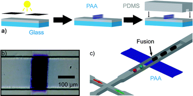 | ||
| Fig. 1 (a) Schematic of surface energy patterned microfluidic device fabrication. Glass supported PDMS substrates previously infiltrated with benzophenone are covered with a solution containing acrylic acid, exposed to UV light and sealed to PDMS moulded microchannels. (b) Micrograph of a microfluidic channel containing a patterned poly(acrylic acid) structure that was stained with toluidine blue. (c) Schematic of a PDMS microfluidic device containing a hydrophilic pattern. Droplets of different components are formed at a double T-junction, and when they encounter the hydrophilic pattern they are trapped, fused and effectively mixed. | ||
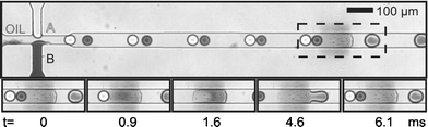 | ||
| Fig. 2 Sequence of surface induced droplet fusion. Droplets of different components approach the hydrophilic pattern (located at the center of the dashed rectangle) (t = 0 ms) before they are trapped and fused (t = 0.9, 1.6 ms). A new droplet combination of both is released (t = 4.6, 6.1 ms). (Channel is 50µm wide and 25µm deep. Hydrophilic pattern is approximately 100µm long.) | ||
When considering the process in more detail, we can divide surface induced droplet fusion in two subsequent processes: droplet trapping and droplet detachment. Droplet trapping can be understood as coalescence between the droplets and the pattern, and depends on the same factors which coalescence in bulk does. Bibette et al.16 have described the case of coalescence induced by a mechanical instability in terms of the distance between the interfaces and the time of contact between them. Coalescence will take place when the interfaces are closer than a critical distance hc (in the order of nanometres) for a time longer than: τ = 96 π2γη h5cA−2where γ is the interfacial tension, η the viscosity of the fluid between the interfaces and A the Hamaker constant. For our system, we have observed that the droplets have to be in close contact with the pattern for a time in the order of tenths of milliseconds to milliseconds. Increasing the droplet velocity will decrease this time of contact ultimately resulting in coalescence prevention. Fig. 3 shows micrographs of a device where no coalescence was observed for a fluid velocity above 55 µm ms−1 which would correspond to an approximate time of contact of 1.8 ms.
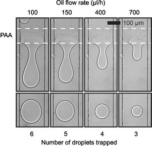 | ||
| Fig. 3 Control of surface induced droplet fusion by variation of fluid velocity. The upper series of micrographs shows the hydrophilic pattern retaining different amounts of water for different oil flow rates. The lower series of micrographs shows the resultant water droplet released for each flow rate. (Channel 200 µm wide, 25 µm deep. Hydrophilic pattern approximately 100 µm long. Water flow rate 5µl h−1.) | ||
Droplet detachment is essentially similar to droplet formation and is governed by the balance between viscous drag force (F ∝ wηv where w is the pattern width, η the viscosity and v the fluid velocity) and interfacial force (F ∝ wγ, where w is the pattern width and γ the interfacial tension). Umbanhowar et al.17 described this balance for an analogous system, formation of droplets from a capillary, in the limit of low Reynolds number. They found that increasing the outer fluid velocity decreases the volume at which the viscous drag overcomes the interfacial tension and causes a droplet to detach. In our case this means that increasing oil speed will induce the detachment of smaller droplets and hence decrease the number of droplets added before droplet detachment. Therefore, controlling the oil speed provides control over the number of droplets fused before a new one is released (Fig. 3). Eventually, increasing the fluid velocity will lead to a time of contact between the droplet and the pattern insufficient for coalescence, as described above. Similar results have been obtained numerically by Kusumaatmaja et al.18 in agreement with both the decrease in number of droplets added as well as the upper speed limit for droplet coalescence.
The results shown in Fig. 3 were obtained by generating droplets at a flow focusing device. This geometry is known to form droplets in a very reliable and controllable manner.6 For a large number of chemical reactions more than two reagents need to be combined simultaneously, several components can be incorporated in a droplet at a single fusion step using devices comprising multiple flow focusing devices and surface energy patterns. Fig. 4 shows a device where droplets of Fe(NO3)3, KSCN and water were formed at three separate flow focusing devices. Upon fusion, a coloured complex (Fe(SCN−)x(3−x)+) was formed in the resultant droplets. For the described device, the process of fusion was not affected by the use of several flow focusing devices nor by the contents of the droplets. Increasing the number of flow focusing devices could potentially provide a tool to combine a large number of components at a single fusion step.
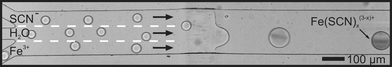 | ||
| Fig. 4 Incorporation of several components into a droplet via a single fusion event. Three different streams of droplets are generated at independent flow focusing devices and combined at the hydrophilic pattern forming droplets containing the three components. After fusion, Fe3+ and SCN− react forming a coloured complex. (Channel 200 µm wide, 25 µm deep. Hydrophilic pattern approximately 100 µm long.) | ||
In summary, we present a new approach for microdroplet control in microfluidic devices. Surface modification can be used to induce fusion of several previously formed droplets. It does not require active elements nor accurate synchronization of droplets, and it is compatible with standard device fabrication techniques. It allows fusion of more than two droplets at a single step and potentially the incorporation of any desired number of components at once. Quantitative characterization of the fusion efficiency depending on the variables of the system (droplet size, channel size, flow rates) is currently in progress.
Acknowledgements
This work was supported by the EPSRC and the RCUK Basic Technology Programme.Notes and references
- H. Song, D. L. Chen and R. F. Ismagilov, Angew. Chem., Int. Ed., 2006, 45, 7336–7356 CrossRef CAS.
- H. Song, J. D. Tice and R. F. Ismagilov, Angew. Chem., Int. Ed., 2003, 42, 767–772.
- A. Huebner, M. Srisa-Art, D. Holt, C. Abell, F. Hollfelder, A. J. deMello and J. B. Edel, Chem. Commun., 2007, 1218–1220 RSC.
- B. Zheng and R. F. Ismagilov, Angew. Chem., Int. Ed., 2005, 44, 2520–2523 CrossRef CAS.
- B. Zheng, L. S. Roach and R. F. Ismagilov, J. Am. Chem. Soc., 2003, 125, 11170–11171 CrossRef CAS.
- S. L. Anna, N. Bontoux and H. A. Stone, Appl. Phys. Lett., 2003, 82, 364–366 CrossRef CAS.
- T. Thorsen, R. W. Roberts, F. H. Arnold and S. R. Quake, Phys. Rev. Lett., 2001, 86, 4163–4166 CrossRef CAS.
- K. Ahn, J. Agresti, H. Chong, M. Marquez and D. A. Weitz, Appl. Phys. Lett., 2006, 88, 264105 CrossRef.
- L.-H. Hung, K. M. Choi, W.-Y. Tseng, Y.-C. Tan, K. J. Shea and A. P. Lee, Lab Chip, 2006, 6, 174–178 RSC.
- D. R. Link, E. G. Mongrain, A. Duri, F. Sarrazin, Z. Cheng, G. Cristobal, M. Marquez and D. A. Weitz, Angew. Chem., Int. Ed., 2006, 45, 2556–2560 CrossRef CAS.
- Y.-C. Tan, J. S. Fisher, A. I. Lee, V. Cristini and A. P. Lee, Lab Chip, 2004, 4, 292–298 RSC.
- Y. Wang, H.-H. La, M. Bachman, C. E. Sims, G. P. Li and N. L. Allbritton, Anal. Chem., 2005, 77, 7539–7546 CrossRef CAS.
- J. C. McDonald, D. C. Cuffy, J. R. Anderson, D. T. Chiu, H. Wu, O. J. A. Schueller and G. M. Whitesides, Electrophoresis, 2000, 21, 27–40 CrossRef CAS.
- Y. Xia and G. M. Whitesides, Angew. Chem., Int. Ed., 1998, 37, 550–575 CrossRef CAS.
- B. Zheng, J. D. Tice and R. F. Ismagilov, Anal. Chem., 2004, 76, 4977–4982 CrossRef CAS.
- J. Bibette, F. L. Calderon and P. Poulin, Rep. Prog. Phys., 1999, 62, 969–1033 CrossRef CAS.
- P. B. Umbanhowar, V. Prasad and D. A. Weitz, Langmuir, 2000, 16, 347–351 CrossRef CAS.
- H. Kusumaatmaja and J. M. Yeomans, Langmuir, 2007, 23, 956–959 CrossRef CAS.
Footnotes |
| † Electronic supplementary information (ESI) available: Video of Fig. 2 and details of device fabrication and microfluidic experiments. See DOI: 10.1039/b708091c |
| ‡ The HTML version of this article has been enhanced with colour images. |
| This journal is © The Royal Society of Chemistry 2007 |