Three-dimensional graphene-based spheres and crumpled balls: micro- and nano-structures, synthesis strategies, properties and applications

Masoud Nazarian-Samani ab, Hyun-Kyung Kimbc, Sang-Hoon Parkd, Hee-Chang Younb, Dattakumar Mhamaneb, Suk-Woo Leeb, Myeong-Seong Kimb, Jun-Hui Jeongb, Safa Haghighat-Shishavanb, Kwang-Chul Roh e, Seyed Farshid Kashani-Bozorg a and Kwang-Bum Kim *b
aSchool of Metallurgy and Materials Engineering, College of Engineering, University of Tehran, 11155-4563, Tehran, IR Iran
bDepartment of Materials Science and Engineering, Yonsei University, 134 Shinchon-dong, Seodaemoon-gu, Seoul 120-749, Republic of Korea. E-mail: kbkim@yonsei.ac.kr
cDepartment of Materials Science and Metallurgy, University of Cambridge, 27 Charles Babbage Road, Cambridge CB3 0FS, UK
dCentre for Research on Adaptive Nanostructures and Nanodevices (CRANN), Trinity College Dublin, Dublin 2, Ireland
eEnergy Efficient Materials Team, Energy and Environmental Division, Korea Institute of Ceramic Engineering and Technology, 233-5 Gasan-dong, Guemcheon-gu, Seoul 153-801, Republic of Korea

Received 22nd March 2016 , Accepted 17th May 2016

First published on 18th May 2016


Abstract

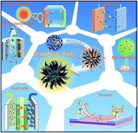
In recent years, three-dimensional (3D) graphene-based architectures have received considerable research attention, comprising both fundamental studies and investigations of potential applications by a number of researchers who have performed exhaustive examinations of the versatile and astonishing properties of these 3D materials, such as their large surface area, excellent electronic and thermal conductivity, superb chemical, thermal, and electrochemical stability, enhanced active material per area, fast ion and electron transportation, superior mechanical strength, and high flexibility. In this critical review, we comprehensively address the primary advancements in 3D spherical and crumpled-ball graphene-based material synthesis techniques. In addition, we provide an overview of their applications in various types of batteries and supercapacitors, as well as in fuel cells, sensors, catalysts, solar cells, and so on, with the aim of discussing these materials' wide range of interesting properties compared with other types of graphene-based structures. Statistical information based on the available literature, which indicates that energy storage devices are more noteworthy research topics than other applications, is also provided. The discussion is concluded with some personal insights into future research direction opportunities, based on the current status of this field. We believe that this review provides critical insights that will further the understanding of the significance of graphene-based spheres and crumpled balls, and, hence, will aid in the further investigation and enhancement of these high-performance nanomaterials from both an interpretative technological and scientific perspective.


image file: c6ra07485e-p1.tif

Masoud Nazarian-Samani

Masoud Nazarian-Samani is a PhD candidate in the School of Metallurgy and Materials Engineering, University of Tehran under the supervision of Prof. S. F. Kashani-Bozorg since 2012, and joined to Prof. K. B. Kim's research group as a visiting student in December 2014. He received his MSc degree in Materials Science and Engineering from K. N. Toosi University of Technology (KNTU), Tehran in 2009, and worked as a senior researcher for more than five years. His current research interests include the synthesis and characterization of holey graphene counterparts and novel 2D materials for next generation batteries.

image file: c6ra07485e-p2.tif

Kwang-Chul Roh

Kwang-Chul Roh received his Ph.D. in Electrical & Electronic Engineering, Yonsei University. He is a principle researcher professor in the Energy Environmental Division and Engineering of Korea Institute of Ceramic Engineering Technology (KICET). He published more than 70 papers and more than 70 patents. His research interests focus mainly on activated carbon, porous materials, flexible electrodes, and supercapacitors.

image file: c6ra07485e-p3.tif

Seyed Farshid Kashani-Bozorg

Seyed Farshid Kashani-Bozorg is an associate professor in the School of Metallurgy and Materials Engineering, University of Tehran. He received his BSc (1984) and MSc degrees (1986) from University of Tehran, and PhD degree (1996) from Imperial College of Science, Technology and Medicine, University of London. He is the author or co-author of more than 40 papers, more than 70 talks at international conferences on various aspects of surface engineering and characterization of metallic and intermetallic materials. The focus of his research has contributed to the surface modification, synthesis and characterization of intermetallic materials for rechargeable batteries.

image file: c6ra07485e-p4.tif

Kwang-Bum Kim

Kwang-Bum Kim is a professor in the Department of Materials Science and Engineering of Yonsei University. He received his BSc degree (1980) from Yonsei University, MSc degree (1982) from Korea Advanced Institute of Science and Technology (KAIST), and PhD degree (1991) from Massachusetts Institute of Technology (MIT). He is the author or co-author of more than 190 papers, more than 100 talks at conferences, several patents, and many invited talks at international conferences on various aspects of advanced batteries and supercapacitors. The focus of his research has contributed to the synthesis and characterization of graphene, CNT and novel 2D materials for energy storage applications.


1. Introduction

Motivated by recent rapid advancements and taking into account the constraints of two-dimensional (2D) graphene, research on graphene-based materials has been directed towards the exploration of different graphene morphologies, with appropriate and attractive contributions from the various scientific fields of physics, chemistry, materials science, and so on. The actual application performance achieved using 2D graphene nanosheets is always less than that anticipated based on its ideal properties of high surface area, high charge carrier mobility, premier mechanical strength, excellent thermal conductivity, etc. This reduced performance is principally due to the agglomeration and restacking of graphene nanosheets as a result of their strong π–π interactions, as well as sheet imperfections and improper dispersion, all of which can inhibit the full realization of the electronic and high-surface-area properties of graphene.1

To overcome the problems of poor dispersion and restacking, several innovative synthesis methods have been introduced. These techniques are designed to create dimension-tailored functional graphene architectures with well-designed morphologies. 3D graphene-based spheres and crumples with large surface areas and abundant pores are among the most promising candidates to overcome the obstacles associated with 2D graphene nanosheets. This is because they exhibit plentiful porous channels with enhanced electrical conductivity and superb structural stability. As a result, a small number of excellent reviews on carbon spheres2–5 and crumpled graphene6 are available, which discuss the majority of recent advances concerning these 3D architectures. Nieto-Márquez et al.2 provided the first overview of carbon nanospheres, focusing principally on carbon onions (diameter: 2–20 nm), spheres (diameter: 50 nm to 1 μm) and beads (diameter: >1 μm), and reported their physicochemical properties for use in various applications. Later, Roberts et al.3 discussed recent research efforts towards the synthesis of porous carbon spheres and monoliths, along with their composites, for application in lithium-ion batteries (LIBs). In that paper, a number of fabrication methods including sustainable biomass and metal–organic framework template-based techniques were reviewed. Zhang et al.4 also focused on various forms of carbon nanospheres, primarily emphasizing the previous three years of research progress in these carbon architectures. More recently, Liu et al.5 reviewed the synthesis methods for nanoporous carbon spheres, particularly highlighting the design of nanoporous carbon spheres at the molecular level. The preparation strategies and various fields of application of graphene-based spherical architectures, however, have been less thoroughly addressed.6,7

Thus, we propose that further comprehensive efforts are needed to fully cover the various synthesis methods for 3D spherical and crumpled-ball graphene-based materials, and their characteristic properties for diverse applications (Fig. 1). This review intends to comprehensively discuss and emphasize the developments and challenges facing 3D spherical and crumpled-ball graphene-based material research only, for the first time. In this review, Section 2 is devoted to statistical information concerning the aforementioned 3D graphene-based materials, which is classified in accordance with the number of publications per year distributed across specific topics, as well as by the synthesis methods employed and the relevant applications. Section 3 describes the established methods of 3D graphene-based material preparation, as well as their relative merits and demerits. Then, Section 4 considers all the properties of 3D graphene-based spheres and crumpled balls examined to date, which are discussed in the context of their diverse potential applications in various research fields. Finally, Section 5 highlights the challenges facing this category of graphene architecture along with the future prospects envisaged.


image file: c6ra07485e-f1.tif
Fig. 1 Schematic representation of 3D graphene-based sphere and crumpled-ball structures, along with their potential applications.

2. Statistical overview

For the purposes of this review, papers relevant to graphene-based spheres and crumpled balls were identified using the two most convenient search engines: Scopus and Google Scholar. To comprehensively evaluate the most recent research activities concerning the aforementioned 3D graphene-based architectures, a total of 73 studies, from more than 850 papers published between June 2010 and October 2015 were screened based on the following keywords: “all carbon types”, “microspheres”, “nanospheres”, “spheres”, “balls”, “nanoballs”, and “crumples”. As mentioned in the previous Section, only “graphene-based materials” will be considered in this review paper. Very few publications dated 2010 and 2011 are available on this topic, as illustrated in Fig. 2a, but the number of publications has increased rapidly since 2012; this confirms that global research investment is fuelling prompt progress in this area and reflects the significant international interest in the morphology and applications of these 3D structured graphene microballs.
image file: c6ra07485e-f2.tif
Fig. 2 Distribution of publications on graphene-based spheres and crumpled balls from June 2010 to October 2015 according to (a) year, (b) synthesis methods, and (c) applications. It should be noted that the papers were screened from among more than 850 research papers, concentrating on the specified keywords only.

Fig. 2b elucidates the most common methods for the synthesis of these 3D graphene-based structures, and indicates that the aerosol-based assembly and template-assisted methods have been utilized most frequently. Both of these methods constitute 49% and 34% of the published pioneering research efforts, respectively, and have clearly demonstrated their capacity for the facile and efficient assembly of graphene nanosheets into 3D spheres or crumpled balls. Water-in-oil (W/O) emulsion and solvothermal methods have been employed to a lesser degree (accounting for 17% of the research in total), but also provide new opportunities for the synthesis of high-performance 3D graphene-based materials with intriguing properties. The distribution of applications of these graphene-based spheres and crumpled balls is diverse, with these materials being used for a variety of devices, most notably batteries (39%), as shown in Fig. 2c. More specifically, a total of 45 papers (62%) have focused on energy storage devices, while other applications such as sensors, catalysts, and fuel cells constitute the remaining 38% of the literature screened.

3. Experimental synthesis strategies

3.1. Template-assisted methods

3D graphene-based spheres can be synthesized using a number of different core materials, which vary in terms of process complexity, sphere size and its distribution, etc. Polystyrene (PS) or poly(methyl methacrylate) (PMMA), silica (SiO2), and metal/oxide-based nanoparticles (NPs) are widely used as core materials for the preparation of 3D spherical graphene-based materials, because of the advantages offered by their simple spherical structure and high scalability (Fig. 3). In this process, the core–shell structure, which is composed of both hard template core materials (SiO2, PS/PMMA, or metal-based NPs) and graphene-based shell materials (GO or reduced graphene oxide (rGO)), is first prepared using the electrostatic attractive interaction between the core and the shell, or through a CVD process using carbon precursors. Then, the core materials are fully eliminated using chemical etching to reveal the final 3D spherical graphene-based materials.
image file: c6ra07485e-f3.tif
Fig. 3 Various template-assisted techniques for 3D graphene-based sphere fabrication.
3.1.1. Spherical PS/PMMA particle-assisted method. Zhang et al.8 first introduced core–shell structured PS-GO microspherical particles, which were prepared by adsorbing GO sheets on the PS surface through a strong π–π stacking interaction. They expected that the core–shell-structured PS/GO composite could provide suitable conductivity for use as an electrorheological (ER) material once an appropriate PS[thin space (1/6-em)]:[thin space (1/6-em)]GO ratio was obtained. Ultimately, the PS/GO-based ER fluid exhibited reversible chain-like structures under an applied electric field, and the shear stress was increased under an increasing external electric field. This work has introduced the possibility for future novel applications involving ER smart materials composed of graphene and GO. Further, based on the findings of Zhang et al., a number of papers associated with the preparation of 3D spherical graphene-based materials have been produced. These studies consider various applications, such as supercapacitors, electro-catalysis, and capacitive deionization.9–14 For example, in 2012, Li et al.12 presented a facile and controllable strategy to fabricate a PS/graphene microsphere-modified electrode for application in electrochemical analysis for dopamine detection. During the polymerization process, 2,2′-azobis-[2-methylpropionamidine] dihydrochloride (AIBA) was used as the cationic initiator to produce positively charged mono-dispersed PS microspheres. In the coating process, GO sheets with abundant sp3 hybridized carbon atoms combined with negatively charged groups were coated on the surface of PS microspheres through electrostatic interaction via low-speed dropwise addition. The electrostatic interaction between the GO and PS microspheres dominated the π–π accumulation. After chemical reduction, the GO sheets coated on the PS microspheres were deoxidized to graphene sheets and the sp3 hybridized carbon atoms became sp2 hybridized. This hybrid material exhibited good electrochemical performance, having an extremely high shell specific surface area (SSA) comparable to the theoretical capacity.

Furthermore, Wang et al.13 have introduced a novel template-directed assembly technique for the fabrication of graphene-coated hollow mesoporous carbon spheres (GHMCSs) with a hierarchical pore structure; these spheres are rationally designed and were originally used as electrode materials for capacitive deionization (Fig. 4). In this technique, phenolic polymer-coated PS spheres prepared through a hydrothermal reaction are designed as templates for the fabrication of the GHMCS architectures; this approach takes full advantage of the hierarchically mesoporous carbon spheres (HMCSs) and graphene. This technique also uses the electrostatic interaction between the positively charged phenolic polymer-coated PS spheres and the negatively charged GO sheets. A good distribution of the HMCSs embedded in the graphene sheets is obtained through electrostatic self-assembly, which prevents graphene aggregation and restacking. Most importantly, the GHMCSs exhibit unique hierarchical pore structures resulting from the HMCSs and the graphene wrappings. Hence, the GHMCSs produced using this technique exhibit superior pore structure leading to enhanced ion infiltration, and the electrosorption capacity is greatly improved during the capacitive deionization process. In addition, this hierarchical structure corresponds to high conductivity due to the presence of the graphene sheets, which guarantees fast charge transfer and low energy consumption in capacitive deionization applications.


image file: c6ra07485e-f4.tif
Fig. 4 Spherical-PS-ball-assisted method using electrostatic interaction between PS ball and graphene sheets for 3D spherical graphene-based material production. (a) Schematic illustration of GHMCS fabrication. SEM and TEM images of (b) and (c) PF@PS; (d) and (e) GO–PF@PS, and (f)–(i) GHMCSs.13 Reprinted with permission from ref. 13. Copyright 2014 Royal Society of Chemistry.

A number of papers have introduced PS/graphene microsphere formation using the CVD technique, as shown in Fig. 5. For example, Lee et al.15 have presented a precursor-assisted CVD technique, in which PS balls and reduced iron created under high temperature and within a hydrogen gas environment constitute a solid carbon source and a catalyst for graphene growth, respectively. Carboxyl acid and sulfonic acid functionalization of the PS ball facilitates homogeneous dispersion of the hydrophobic polymer template in the metal precursor solution, which results in mesoporous graphene balls (MGBs) with a uniform number of graphene layers. The MGBs have been shown to have a SSA of 508 m2 g−1 and have a mean mesopore diameter of 4.27 nm.


image file: c6ra07485e-f5.tif
Fig. 5 Spherical-PS-ball-assisted method using CVD for production of 3D spherical graphene-based materials. (a) Functionalization of PS via carboxylation and sulfonation (SPS-COOH: sulfonated poly(styrene-co-methacrylic acid)) and sample Fourier transform infrared (FT-IR) spectra. (b) MGB fabrication process: step 1, drop casting of SPS-COOH/ferric chloride (FeCl3) solution onto the substrate and subsequent CVD-assisted graphene growth; step 2, removal of Fe domains leaving MGB. SEM images of (c) SPS-COOH and (d) MGB obtained through CVD of sample (c). (d, inset) Magnified SEM image of single MGB. (e) TEM images of MGB taken near sample edges. The inset shows that there are ∼7 layers in the MGB with an interlayer spacing of 0.34 nm. (f) Magnified image of single MGB.15 Reprinted with permission from ref. 15. Copyright 2013 American Chemical Society.

Very recently, researchers10,11 have attempted to employ spherical PMMA templates in the formation of 3D spherical graphene-based materials. In 2013, Chen et al.11 reported a method to promote photoluminescent emission in graphene materials by enhancing carrier scattering. The strategy for the formation of 3D spherical graphene-based materials using a PMMA template employed by these researchers is closely analogous to that using a PS micro-ball template. First, they formed PMMA/graphene spheres, and then they removed the PMMA template using chemical etching. They intentionally curled the graphene layers to form 3D spherical graphene-based materials, which produce hot-carrier luminescence with an emission efficiency that is more than ten-fold greater than that of planar graphene nanosheets. Further, Trung et al.10 reported another attempt to use spherical PMMA templates for the fabrication of 3D spherical graphene-based materials, in 2014. In their strategy, a positively charged PMMA sphere template interacted with negatively charged GO sheets in an aqueous system as a result of the electrostatic attraction between them. Specifically, chemically exfoliated graphene sheets were self-assembled on the surfaces of PMMA colloidal particles used as templates. This was followed by the synthesis of polyaniline (PANI) and the removal of the core PMMA particles.

3.1.2. SiO2 template-assisted method. SiO2 can also be a good candidate as a template for the formation of 3D spherical graphene-based materials because of its uniform spherical structure and its easy removal by chemical etching.16–22 For example, Wu et al.20 have demonstrated novel rGO-based hollow spheres as efficient metal-free catalysts for oxygen reduction reaction (ORR) in alkaline media. In this technique, the SiO2 spheres are first modified with polyethylenimine (PEI), and then added to negatively charged GO suspensions. Through the strong electrostatic attraction between the PEI and GO, the SiO2 spherical cores are coated with GO sheets. The core–shell structures are dried and subsequently immersed in a Na–NH3 solution in order to reduce the GO sheets and obtain rGO. After washing with abundant ethanol (C2H6O) and water, concentrated hydrofluoric acid (HF) is applied to remove the SiO2 cores. To improve the crystallization quality and to remove the polymer, heat treatment is performed, in which the rGO-coated SiO2 spheres are annealed at high temperature.

Recently, Liu et al.19 fabricated hierarchical graphene@PANI@graphene sandwiches containing the hollow spheres shown in Fig. 6. In order to achieve this unique structure, GO-encapsulated SiO2 spheres (GO@SiO2) were first fabricated via electrostatic interactions between the positively charged SiO2 and the negatively charged GO. Then, a layer of PANI was polymerized on the GO@SiO2 surface, and the SiO2 was etched to yield hollow PANI@GO spheres. Lastly, graphene@PANI@graphene nanocomposite was obtained through a repeated self-assembly process of coating with GO and a reduction reaction. Graphene was used as both an internal skeleton shell and a cladding layer to coat the PANI. In this approach, the morphology of the hollow structure and the sandwich layer can be controlled by optimizing the aniline monomer concentration and the size of the SiO2 template, respectively. This in turn optimizes the electrochemical performance.


image file: c6ra07485e-f6.tif
Fig. 6 Spherical-SiO2-assisted method using electrostatic interaction between SiO2 ball and graphene sheets for 3D spherical graphene-based materials. (a) Schematic illustration of formation process of graphene@PANI@graphene sandwich with hollow structures, (b) SEM image of SiO2, and (c) atomic force microscopy (AFM) image of GO. SEM images of (d) GO@SiO2, (e) PANI@GO@SiO2, (f) graphene@PANI@graphene.19 Reprinted with permission from ref. 19. Copyright 2015 American Chemical Society.

So far, we have discussed studies on the fabrication of 3D spherical graphene-based materials following removal of an SiO2 template through chemical etching. However, in 2014, Wu et al.23 reported a novel type of 3D porous Si–graphene micro/nanostructure in the form of a spherical network that was realized using layer-by-layer assembly and a subsequent in situ magnesiothermic-reduction methodology. These researchers used a core SiO2 template as the starting material for the formation of Si as an anode material for LIB applications. As regards the synthesis procedure, they first formed SiO2/graphene oxide spherical networks via layer-by-layer assembly based on the electrostatic attraction between these materials. Then, they reduced the SiO2 to Si using an in situ magnesiothermic-reduction approach. These researchers claim that their novel 3D porous Si–graphene micro/nanostructure in spherical-network form exhibits superior electrochemical properties to those of a bare Si sphere, because of its unique structural features. In addition, Xiao et al.24 have developed raspberry-like SiO2@rGO/Ag microspheres. This has been achieved using sonication-assisted self-assembly of small GO sheets, with a lateral size of less than 200 nm, on a cationic polyelectrolyte-modified SiO2 microsphere substrate with high aqueous dispersity and exceptional catalytic activity toward the reduction reaction of 4-nitrophenol by sodium borohydride (NaBH4).

3.1.3. Metal/oxide-based NP-assisted method. Metals or metal oxides are also applicable candidate template materials as regards the formation of core–shell structures for 3D spherical graphene-based materials, because of their uniformly spherical shape and their easy removal.25–28 Yoon et al.29 first reported the fabrication of multilayer graphene balls via template-directed carbon segregation using Ni NPs as template materials. To maintain the ball shape of the template Ni NPs, they employed a carburization process using polyol solution as the carbon source, along with a thermal annealing process, to synthesize graphene layers via carbon segregation on the outer surface of the Ni-NP. The graphene ball preparation consisted of three steps: (i) a carburization process where carbon was diffused into the starting Ni-NPs using a polyol solution and aided by the catalytic reaction of Ni, so as to prepare carbon-incorporated Ni-NPs; (ii) the formation of multilayer graphene-encapsulated Ni NPs via carbon segregation through thermal annealing of the carbon-incorporated Ni particles; and (iii) dissolution of the core metal NPs using an acidic solution to yield hollow graphene balls.

Kim et al.30 have also presented a graphene ball preparation technique using Ni NPs as a spherical template, as shown in Fig. 7. However, they employ a simple and up-scalable method to produce highly repaired GO with a large surface area, by introducing spherical multi-layered graphene balls with empty interiors. These graphene balls are prepared via CVD of Ni particles on the GO surface. After removing the Ni using hydrochloric acid (HCl), the resultant repaired GO with graphene balls (RGGBs) have a superior electrical conductivity of 18[thin space (1/6-em)]620 S m−1 and a large SSA of 527 m2 g−1. Moreover, the recyclability of the Ni catalyst means that this process is more attractive to industry, as it is environmentally friendly.


image file: c6ra07485e-f7.tif
Fig. 7 Metal- or metal-oxide-NP-assisted method for 3D spherical graphene-based material fabrication. (a) Schematic illustration of hollow graphene ball (GB) synthesis. SEM and high-resolution TEM (inset) images of (b) carbon-incorporated Ni-NPs, (c) multilayer-graphene-encapsulated Ni-NPs, and (d) GBs.29 Reprinted with permission from ref. 29. Copyright 2012 American Chemical Society.

He et al.31 have reported 3D hollow porous graphene balls (HPGBs), which are synthesized directly from coal tar pitch through a simple nano-MgO template strategy coupled with potassium hydroxide (KOH) activation. The as-made HPGBs exhibit a 3D spherical architecture with a thin porous shell having a high SSA and consisting of macropores, mesopores, and micropores in a well-balanced ratio. In this preparation process, coal tar pitch liquefied at 423 K is coated onto the surfaces of nano-sized MgO particles. These particles function as a template to form thin coating layers composed of aromatic hydrocarbons derived from the coal tar pitch. Meanwhile, KOH mixed in the pitch in the grinding step becomes embedded in the thin coating layers. In the subsequent heating step, gaseous products form in situ in the thin carbonaceous coating layers, as a result of hydrocarbon decomposition. The coating layers gradually transform into thin carbon layers with a ball-like architecture, because of the combined effect of the internal gas pressure. This is due to hydrocarbon decomposition and reorganization, along with the MgO template effect. Subsequently, the KOH embedded in the coating layers activates the aromatic hydrocarbons at elevated temperatures to create differently sized pores in the ball-like shells of the thin carbon layers.

Recently, spherical 3D graphene-based materials were fabricated using various core metals such as MgAl-LDH, α-Fe2O3, and Ni. For example, Shi et al.26 have reported the direct synthesis of graphene microspheres assembled using 3D interconnected graphene with hierarchical pores via template CVD on layered double-oxide (LDO) microspheres. The LDO templates were derived from conformally calcined layered double-hydroxide microspheres produced via spray drying. After methane-CVD, graphene was catalytically grown on the LDO templates. Subsequent routine chemical etching of the LDO templates enabled as-obtained graphene microspheres with a large diameter of ca. 11 μm and a high surface area of 1275 m2 g−1. Also, Lee et al.27 introduced a sea-urchin-shaped template approach for the fabrication of highly crumpled graphene balls in bulk quantities via a simple process. Simultaneous chemical etching and reduction of GO-encapsulated α-Fe2O3 particles resulted in dissolution of the core template with a spiky morphology and conversion of the outer GO layers into rGO layers with increased hydrophobicity. These layers remained in contact with the spiky surface of the template. Finally, Sun et al.25 successfully produced a novel porous and N, S-codoped spherical graphene-like material via precursor-assisted CVD. Following use of ammonium persulfate ((NH4)2S2O8) as an N and S dopant, the as-prepared 3D NS-graphene spheres exhibited a higher surface area than those of pristine graphene-like microspheres.

In summary, 3D spherical graphene-based materials have been widely studied using template-assisted methods involving PS/PMMA balls, SiO2 balls, and metal/metal oxide-based NPs, which are efficient for large-scale production at low cost. Materials fabricated using these methods have balanced pore distribution in the shells of the 3D spherical graphene-based architectures, which helps to improve the electron conductivity and to reduce the ion transfer resistance. This is because the abundant porous channels and active sites in the thin carbon shells allow for the storage and fast transportation of electrolyte ions, which in turn leads to higher electrochemical performance in various applications, such as supercapacitors, LIBs, and gas sensors.

3.2. Solvothermal

The solvothermal technique is also one of the important synthesis strategies for the fabrication of 3D graphene-based spheres and crumpled balls, particularly owing to its advantages in relation to a wide variety of potential applications.32 Wang et al.33 have reported template-free solvothermal synthesis involving the reduction of hexachlorobutadiene (C4Cl6) by sodium (Na) in an autoclave at a moderate temperature, in which the reaction pressure was employed as a means of manipulating the morphology of the final products. The graphene sheets were the dominant reaction products, with their morphology being changed to nanospheres by adjustment of the pressure inside the autoclave. To further examine the importance of reaction pressure in the tuning of the 3D morphology, solvothermal reactions were also conducted at a configuration where the autoclave was completely filled with C4Cl6. Then, thermal expansion of the C4Cl6 liquid in response to the elevated temperature caused a pressure increase and, hence, porous graphene nanospheres were obtained. Further, Cao et al.34 have presented hollow graphene spheres that were self-assembled via a one-step hydrothermal method. First, they controlled the agglomeration of GO sheets in aqueous solution by controlling the pH. Then, the GO aqueous suspension was transferred to a teflon-lined autoclave and heated at 160 °C for 10 h, through which the GO sheets were self-assembled to yield hollow graphene spheres.

Recently, Jiang et al.35 reported a combined synthesis of template and solvothermal methods for the production of B and N co-doped hollow graphene microspheres. They used amino-modified SiO2 spheres (NH2–SiO2) of approximately 500 nm in size as sacrificial templates to form a stable suspension consisting of ammonia boron trifluoride (NH3BF3) and a GO wrapped NH2–SiO2 solution. This was sealed in a Teflon-lined autoclave for hydrothermal treatment at 180 °C for 12 h. After freeze drying and calcination in an Ar atmosphere at 420 and 800 °C for selected periods of time, the sample was washed with a 10 wt% aqueous HF solution so as to remove the templates. The spherical structures of the graphene microspheres were retained after removal of the SiO2 templates. Further, Sun et al.36 produced N-doped graphene microspheres using a combination of CVD and hydrothermal methods, which resulted in a greatly interconnected graphene framework with a high degree of crystallization, a large surface area, and proper N doping. This process primarily consists of mixing of the Ni and PMMA powders and hot pressing into a cylinder at 200 °C. Then, the sample is heat treated at 1000 °C under an Ar/H2 atmosphere, and graphene is subsequently precipitated on the Ni surface during rapid cooling. Next, the Ni template is removed by washing with the HCl solution, and doped 3D graphene microspheres are formed after the hydrothermal process using urea at 200 °C.

Microwave irradiation has also become a widespread energy source of choice for various nanomaterial synthesis techniques. In particular, its application in the synthesis of 3D graphene-based architectures with controlled shape and size without the need for high pressures or temperatures has been demonstrated. Microwave irradiation has several advantages in this regard, as it facilitates reaction kinetics and selectivity, and also has the capability to realize reactions in a very short time.37 For example, Zheng et al.38 dispersed natural graphite flakes in a dioxane solution and produced graphene nanospheres at the solution boiling point (101 °C), with the assistance of sparks induced by the microwave irradiation (Fig. 8). The graphene nanospheres, which had 15–45 graphitic layers and diameters in the hundreds of nanometers, were produced through the rolling of the annealed GO. Then, graphite and other non-soluble materials were removed from the suspension through centrifugation, and a homogeneous suspension of graphene nanospheres in solvent was acquired. All the graphene nanospheres contained a single hollow cavity of 100–1000 nm diameter. Fig. 8a shows the proposed mechanism. First, the graphite flakes are heated to a high temperature upon exposure to the microwave radiation. Some areas of the GO that are close to the hot graphite are transformed into graphene (step 1). On account of the superior heat absorption of rGO compared to GO, a large strain discrepancy is induced by the temperature difference between the hot graphene and cooler, surrounding GO, which creates surface strain and causes the graphene sheet to roll into a spherical shape (step 3). Then, the remaining GO parts are rolled onto the hot sphere (step 4). Finally, the GO sheets are fully rolled into graphene nanospheres through further heat treatment (step 5).


image file: c6ra07485e-f8.tif
Fig. 8 (a) Schematic illustration of processes involved in graphene nanosphere formation. The graphite flakes are strongly heated by the microwaves, and the resulting thermal radiation heats a small area on the GO sheet (steps 1 and 2); the small area anneals to a small graphene sphere (step 3); the surrounding residual GO rolls up on the hot sphere layer-by-layer, like a “rolling snowball” (step 4); finally, the graphene nanospheres are formed (step 5). The red color denotes a high temperature area. (b–f) Bright-field TEM images corresponding to steps 1–5 in the graphene nanosphere formation process.38 Reprinted with permission from ref. 38. Copyright 2011 Springer.

Graphene-based microspheres with various metal oxides/sulfides have also been reported, which are intended for use in a variety of applications including energy storage devices and as catalysts.39–41 The synthesis process for graphene-based microspheres primarily consists of two parts: (i) a solvothermal method, and (ii) a subsequent annealing process. In the first step, the metal oxides/sulfides are precipitated on the surfaces of graphene sheets, and the morphology of the graphene is changed from sheet to sphere through further heat treatment or self-assembly processes. For example, Liu et al.40 have reported the synthesis and characterization of molybdenum disulfide (MoS2)/graphene microspheres for Mg batteries using a hydrothermal method. During this hydrothermal process, layered MoS2 grows on the graphene surface, which acts as a substrate; this distinctive structure restrains the stacking of the MoS2 and graphene nanosheets. Subsequently, the hybrid nanosheets self-assemble into sandwich-structured microspheres through intermolecular forces.

Further, Palanisamy et al.39 have synthesized molybdenum oxide (MoO2)/graphene microspheres via microwave hydrothermal treatment followed by thermal annealing. Fig. 9 shows the synthetic mechanism used. In this process, hydrolysis of a (NH4)6Mo7O24·4H2O precursor along with GO sheets is conducted in a closed aqueous system, in the presence of ascorbic acid (C6H8O6; a non-toxic reducing agent). A microwave-assisted hydrothermal (MAH) process is also conducted, which leads to the formation of small clusters of MoO2/graphene composite. Under microwave irradiation, a large quantity of fine primary unstable MoO2 nuclei with high surface energy is formed, resulting from faster crystal growth. The final product then has a narrow size distribution. The small cluster of as-prepared MoO2/graphene composite is converted into highly crystalline and porous self-assembled microspheres through thermal annealing in a N2 atmosphere.


image file: c6ra07485e-f9.tif
Fig. 9 Schematic formation process of MoO2/rGO hybrid microspheres. The hydrolysis of an ammonium heptamolybdate tetrahydrate [AHM: (NH4)6Mo7O24·4H2O] precursor along with GO sheets in a closed aqueous system in the presence of ascorbic acid (C6H8O6), accompanied by an MAH process, leads to the formation of small clusters of MoO2/graphene composite. Under microwave irradiation, a large quantity of fine primary unstable MoO2 nuclei with high surface energy is formed, resulting from faster crystal growth and yielding a final composite with a narrow size distribution. The small cluster of as-prepared MoO2/graphene composite is converted into highly crystalline and porous self-assembled microspheres by thermal annealing in a N2 atmosphere (500 °C, heating rate: (10 K min−1) for 5 h).39 Reprinted with permission from ref. 39. Copyright 2015 Elsevier.

Recently, Liu et al.42 produced PS@rGO Pt core–shell microspheres through the microwave-assisted reduction of GO and chloroplatinic acid (H2PtCl6) as a Pt precursor in a commercial microwave oven, without the use of any surfactants or polyelectrolytes. These microspheres were intended for application as a non-enzymatic electrochemical sensor for sensitive detection of hydrogen peroxide (H2O2). GO nanosheets were attached to the surface of a PS microspheres via π–π interaction. The majority of the oxygen groups were removed from the GO during the microwave process, and the H2PtCl6 was reduced to Pt nanoparticles attached to the microspheres. The PS microspheres were used as the core to support the rGO nanosheets and Pt nanoparticles, and also efficiently hindered the agglomeration of the electrode material, which led to a high active surface area for electrochemical reactions. The rGO–Pt nanocomposite had the form of a wrinkled shell of 20–43 nm thickness attached to the surface of the PS core.

3.3. Aerosol-based assembly

The aerosol-based assembly method has been applied widely, in order to assemble graphene nanosheets into both 3D spherical and crumpled graphene structures on a micrometer scale. Generally, this method can synthesize spherical particles through the aerosolization of micro-droplets from a precursor solution, followed by subsequent evaporation/decomposition in a high-temperature reactor. This temperature must be higher than the evaporation temperature of the solvent. Recently, this method has proven to be very useful for the assembly of 2D graphene nanosheets into micro-structured graphene architectures, such as crumpled particles or microspheres. Fig. 10 shows two schematic images of experimental apparatus for aerosol-based assembly methods, consisting of aerosol generators (Fig. 10a: ultrasonic atomizer, and Fig. 10b: air spray nozzle) for atomization of the precursor solution, a high-temperature reactor for evaporation of the solvent, and a filter or vessel for particle collection.
image file: c6ra07485e-f10.tif
Fig. 10 Schematic diagrams of aerosol-based assembly method experimental apparatus and synthetic process. Generally, this method involves the following steps: graphene nanosheets containing a precursor solution are aerosolized with aerosol generators, using either (a) ultrasonic atomizer- or (b) air spray nozzle-assisted apparatus; the aerosol is transported into a high-temperature reactor by a carrier gas; and the graphene nanosheets are assembled into spherical microstructures by the capillary force generated during the evaporation process.43,60 (a) Reprinted with permission from ref. 43. Copyright 2011 American Chemical Society. (b) Adapted with permission from ref. 60. Copyright 2013 American Chemical Society.

The micro-assembled graphene particle (either crumpled or spherical graphene) fabrication process using an aerosol-based assembly method can be described as follows: graphene nanosheets (typically GO) are uniformly dispersed in a solvent (typically water) as basic building blocks. Aerosol droplets are then generated from this solvent by an ultrasonic atomizer or spray system, which are then transported to a high-temperature reactor by a carrier gas. The evaporation of the solvent in the high-temperature reactor causes droplet shrinkage, which first concentrates the nanosheets and subsequently compresses them into sub-micrometer crumpled particles via the capillary force during the drying process. Here, the particle formation reaction is confined within the space of a single droplet that can act as a micro-reactor. Thus, the particle maintains the droplet shape, resulting in a spherical structure. In addition, this aerosol-based strategy can be easily scaled up using a continuous supply of precursor solutions. Therefore, it is considered to be one of the more effective methods that can meet the requirements for industrial implementation.

Based on this synthetic mechanism, Luo et al. first employed an aerosol-based assembly method using combined atomizer/furnace equipment to prepare crumpled graphene particles.43,44 The morphological evolution they reported suggests that each aerosol droplet produces one crumpled particle, and the crumpled particle sizes can be tuned through the concentration of GO in the aerosol droplets, as shown in Fig. 11a. More importantly, they demonstrated that the crumpled graphene particles are remarkably aggregation-resistant as a result of their assembled structure. Fig. 11b shows that the flat or wrinkled graphene nanosheets can be easily stacked and greatly flattened in the horizontal direction under compression stress, because of the high aspect ratio of the 2D nanosheet morphology. In contrast, the crumpled balls have a near spherical contour, thus, they can resist compression from any direction without unfolding. This characteristic may help the balls to maintain the interesting surface morphologies of graphene itself, which should greatly benefit applications using bulk quantities of graphene, such as energy storage or conversion devices. In particular, Luo et al.43,44 clearly demonstrated that the crumpled graphene particles can be used as a supercapacitor electrode material that exhibits excellent electrochemical performance. Even if the mass of the electrode materials is increased, only minimal restacking of the graphene nanosheets is observed. This is not observed for other supercapacitors prepared from flat or wrinkled graphene nanosheets. Further, the crumpled graphene particles synthesized through the aerosol-based assembly method are immune to agglomeration and maintain a large accessible surface area for electrochemical reactions.


image file: c6ra07485e-f11.tif
Fig. 11 (a) SEM images of crumpled graphene particles prepared using an aerosol-based assembly method.43 (b) Stacking tendency of flat graphene, wrinkled graphene, and ball-like crumpled graphene particles. While the flat or wrinkled graphene nanosheets can be easily stacked/flattened into paper-like structures under compressive stress, the crumpled balls can resist compression from any direction without unfolding because of their near-spherical contours.44 (a) Reprinted with permission from ref. 43. Copyright 2011 American Chemical Society. (b) Reprinted with permission from ref. 44. Copyright 2013 American Chemical Society.

Since the publication of this pioneering study by Luo et al., extensive efforts have been directed toward the development of a spray-assisted method for the synthesis of crumpled or microspherical graphene-based materials for use in various applications.43–76 Table 1 summarizes recent progress on the graphene-based materials synthesized using the aerosol-based assembly method. For example, Qiu et al. have reported that crumpled graphene particles can be synthesized simply using commercial spray dryer equipment (B-190 Mini Spray Dryer, Buchi). They have also shown that these particles exhibit promising capacitive performance (high specific capacity and rate-capability) even compared with activated carbon, which is the commercialized electrode material used for supercapacitors.54 Also, Parviz et al. have reported that not only graphene oxide, but also pristine graphene nanosheets can be assembled into crumpled graphene particles by employing an aerosol-based assembly method, with optimization of the precursor solvent and aerosolization conditions.55 Furthermore, this method can be tuned by adjusting the synthetic conditions, or it can be combined with post treatment to modify the properties of the resultant materials. For example, Mei et al. have successfully synthesized spherical, hollow graphene structures rather than crumpled graphene particles by introducing post heat treatment with the assistance of citric acid (C6H8O7).56 Here, the C6H8O7 was dissolved in the precursor GO dispersion and acted as a cross-linker between GO nanosheets during the aerosol-based assembly process. Hollow graphene microspheres were finally obtained after heat treatment (Fig. 12a).

Table 1 Summary of 3D graphene-based spheres and crumpled balls synthesized using aerosol-based assembly methods
Structure Synthetic apparatus Highlights Applications Refs.
Crumpled graphene Ultrasonic atomizer Pioneering study on crumpled graphene using spray-assisted method Microbial fuel cell, supercapacitor 43 and 44
Precursor: GO dispersion High compression and aggregation resistance
  SSA: 567 m2 g−1
MoO3–rGO microsphere Commercial spray dryer Applying a water-soluble metal salt LIB anode 45
Precursor: GO/ammonium molybdate
GeOx-coated rGO balls Spray drying Amorphous GeOx-coated rGO balls with sandwich structure via spray pyrolysis using PS nanobeads as sacrificial templates LIB anode 46
Precursor: GO/GeO2/PS dispersion
Crumpled graphene/TiO2 Ultrasonic atomizer 3D crumpled graphene incorporated into TiO2 film Dye-sensitized solar cells 47
Precursor: crumpled graphene/TiO2
Crumpled graphene–TiO2–magnetite Ultrasonic atomizer Ternary core–shell nanostructures Photocatalyst (water treatment) 48
Precursor: GO/commercial magnetite/TiO2
MoSx/crumpled graphene balls Ultrasonic atomizer MoSx grown (by dip coating) on crumpled graphene-modified carbon cloth Electrocatalytic hydrogen production 49
Precursor: ammonium tetrathiomolybdate (NH4)2MoS4)/carbon cloth modified with crumpled graphene
N-doped crumpled graphene-CoO Ultrasonic atomizer The first report on using crumpled graphene with nanocrystals as bi-functional electrocatalysts ORR and OER 50
Precursor: cobalt dichloride (CoCl2) dissolved in GO dispersion
Crumpled graphene ball/Au Ultrasonic atomizer Highly conductive crumpled graphene ball decorated with Au nanoparticles Label-free immunosensor 51
Precursor: mixture of gold(III) chloride trihydrate (HAuCl4·3H2O) and GO
Porous graphene–SnO2 microspheres Ultrasonic atomizer The first report on using porous graphene–metal oxide microspheres as an anode material for LIBs LIB anode 52
Precursor: solution of Sn oxalate salt, PS nanobeads, and GO SSA: 120 m2 g−1
Crumpled graphene ball-nanocrystal hybrids (like Mn3O4, SnO2, Pt, Ag) Ultrasonic atomizer Using monolayer and multilayer GO with different lateral sizes to evaluate the difference in the resulting crumpled graphene structure Supercapacitor/LIB anode 53
Precursor: dissolution of metal ions (Mn(NO3)2·4H2O, SnCl4·5H2O, AgNO3, H2PtCl6) in the GO suspension
Crumpled graphene Commercial spray dryer Highly crumpled structure Supercapacitor 54
Precursor: GO dispersion SSA: 385 m2 g−1
Crumpled graphene Commercial spray dryer Study on effects of solvent type on re-dispersion property 55
Precursor: GO or graphene/surfactant dispersions
Hollow graphene microsphere Ultrasonic atomizer Synthesis of hollow graphene microsphere using post-heat treatment process with the assistance of citric acid LIB anode 56
Precursor: GO/citric acid dispersion SSA: 175.5 m2 g−1
Macro/mesoporous graphene microsphere Ultrasonic atomizer Formation of macro/mesoporous structure using post-KOH-activation treatment Supercapacitor 57
Precursor: GO dispersion SSA: 3290 m2 g−1
Microwave expansion and KOH activation  
Graphene microsphere Modified spray system (spray-assisted deep frying process) Arrangement of graphene nanosheets in radially outward direction Supercapacitor 58
Precursor: GO dispersion SSA: 365 m2 g−1
Si/graphene microsphere Ultrasonic atomizer First study of graphene-based hybrid microspheres using spray-assisted method LIB anode 59
Precursor: Si/GO dispersion Synthesis of Si-entrapped graphene microsphere
Fe2O3/graphene microsphere Commercial spray dryer Synthesis of Fe2O3-entrapped graphene microsphere LIB anode 60
Precursor: Fe2O3/GO dispersion
Li4Ti5O12/graphene microsphere Commercial spray dryer Synthesis of Li4Ti5O12-entrapped graphene microsphere LIB anode 61
Precursor: Li4Ti5O12/GO dispersion
Si/graphene microsphere Modified spray system (spray-assisted deep frying process) Synthesis of Si-entrapped graphene microsphere LIB anode 58
Precursor: Si/GO dispersion Arrangement of graphene nanosheets in radially outward direction
Ni/NiO graphene microsphere Ultrasonic atomizer Synthesis of core/shell-structured Ni/NiO-entrapped graphene microsphere using spray pyrolysis of Ni nitrate ion and post-Ni-oxidation treatment LIB anode 62
Precursor: Ni(NO3)2·6H2O dissolved GO dispersion
CoO/graphene microsphere Ultrasonic atomizer Synthesis of CoO entrapped graphene microsphere from spray pyrolysis of CoCl2 Enzymeless glucose detection sensor 63
Precursor: CoCl2 dissolved in GO dispersion
V2O5/graphene microsphere Ultrasonic atomizer Synthesis of V2O5-entrapped graphene microsphere from spray pyrolysis of NH4VO3 ion LIB cathode 64
Precursor: ammonium vanadate (NH4VO3) dissolved in GO dispersion
Urchin-like CuxO-coated graphene microsphere Spray drying Synthesis of urchin-like CuxO onto graphene microsphere through spray pyrolysis and post-heat treatment Photocatalyst 65
Precursor: Cu(AC)2 dissolved in GO dispersion
Au or Pt/graphene microsphere Ultrasonic atomizer Synthesis of noble-metal-entrapped graphene microsphere using spray pyrolysis Glucose biosensor 66
Precursor: NH4VO3 dissolved in GO dispersion
WS2/graphene microsphere Spray drying Synthesis of WS2-entrapped graphene microsphere using spray pyrolysis and post sulfidation Na-ion battery anode 67
Precursor: ammonium tungstate/polystyrene nanobeads/GO dispersion
ZnS/graphene microsphere Spray drying Synthesis of ZnS-entrapped graphene microsphere using one-pot spray pyrolysis and sulfidation LIB anode 68
Precursor: ZnCl2/GO dispersion
CNT/graphene microsphere Ultrasonic atomizer Synthesis of CNT-decorated graphene microsphere using spray pyrolysis Supercapacitor 69
Precursor: FeCl3 dissolved in GO dispersion
CVD growth of CNT
CuxO–CNTs/graphene microsphere Spray drying Synthesis of CuxO-CNTs/graphene microsphere using spray pyrolysis and post-heat treatment Photo catalyst 70
Precursor: Cu(AC)2 dissolved in CNT/GO dispersion
Pyrolyzed (C3H3N)n–S@graphene microsphere Commercial spray dryer Synthesis of (C3H3N)n microsphere using spray pyrolysis and post-sulfur-melting diffusion method Li–sulfur battery 71
Precursor: (C3H3N)n/GO dispersions
Melting diffusion method for sulfur coating on (C3H3N)n/GO microsphere
Si@ carbon@ void@ graphene microsphere Ultrasonic atomizer Synthesis of Si/carbon/graphene by spray pyrolysis and post carbonization LIB anode 72
Precursor: Si/PVP/GO dispersion
Nickel sulphide–rGO microsphere Ultrasonic atomizer Mesopores of 3.5 nm in size LIB anode 73
Precursor: nickel nitrate (Ni(NO3)2) and thiourea ((NH2)2CS)/GO dispersion
NiFe2O4@NiO–hollow-nanosphere decorated rGO Ultrasonic atomizer Efficient usage of different diffusion rates and radii of Ni and Fe cations during nanoscale Kirkendall diffusion to fabricate multiphase and double-layer NiFe2O4@NiO hollow nanospheres LIB anode 74
Precursor: nickel nitrate hexahydrate (Ni(NO3)2·6H2O), iron nitrate nonahydrate (Fe(NO3)3·9H2O), and GO dispersion
Crumpled graphene ball–PtAu alloy Ultrasonic atomizer SSA: 238 m2 g−1 Electrocatalyst for direct methanol fuel cell 75
Precursor: chloroplatinic acid hexahydrate (H2PtCl6·6H2O), gold(III) chloride trihydrate (HAuCl4·3H2O), GO, and sodium borohydride (NaBH4) dispersion
Crumpled graphene–molybdenum oxide Ultrasonic atomizer Synthesis of crumpled graphene-MoO2 composite powders directly by spray pyrolysis LIB anode 76
Precursor: AHM in GO dispersion Transition into MoO3 after subsequent heat treatment at 300 °C


image file: c6ra07485e-f12.tif
Fig. 12 Synthetic schemes and microscopic images showing spherical microstructure of graphene obtained through modified aerosol-based assembly method. (a) Hollow graphene micro-ball synthesized using this method with the assistance of C6H8O7 as a cross-linker,56 and (b) graphene microsphere assembled using a spray-assisted deep frying method and a high-temperature organic solvent.58 (a) Reprinted with permission from ref. 56. Copyright 2015 Elsevier. (b) Reprinted with permission from ref. 58. Copyright 2015 American Chemical Society.

Kim et al. also modified crumpled graphene by introducing a post activation treatment to cause the formation of an additional pore structure.57 They synthesized meso-/macroporous crumpled graphene through KOH activation; the resultant graphene structure exhibited an extremely high SSA of 3290 m2 g−1. As a result of the bimodal pore system, this crumpled graphene exhibited excellent electrochemical performance in various electrolytes for supercapacitor application. On the other hand, our group has recently reported a modified aerosol-based assembly method using a high-temperature organic solvent (deep-frying assembly method) for the synthesis of graphene microspheres with a uniform pore structure (Fig. 12b).58 In this system, GO microdroplets are sprayed downward into the high-temperature organic solvent. Then, the water inside the droplets can be quickly evaporated. The escaping water vapor generates nanochannels radiating outward from between the assembled nanosheets inside the final graphene microsphere.

The aerosol-based assembly method can be applied even if there are other components in the starting GO dispersion; this allows them (graphene nanosheets and other materials) to be assembled together into a hybrid microstructured material.58–61 Luo et al. first developed this assembly method for the preparation of NP-encapsulated graphene microstructures (crumpled graphene-encapsulated Si NPs).59 By introducing only additional NPs (50–100 nm Si) to the starting GO dispersion, the graphene/NP hybrid microstructure (crumpled graphene wrapped particles) can be synthesized simply using the same aerosol-based assembly method. Scanning electron microscopy (SEM) and elemental mapping images of the obtained structures clearly show that the majority of the NPs are efficiently entrapped by the graphene nanosheets; hence, the successful synthesis of graphene wrapped hybrid material via this method has been demonstrated. Further, Zhou et al. have also reported Fe2O3-encapsulated graphene microstructures synthesized from NPs containing a GO dispersion.60 In this technique, the Fe2O3 NPs are efficiently entrapped in the graphene microstructures and the morphology of the resultant hybrid material is more similar to a microsphere than a crumpled particle. It is believed that, during the aerosol-based assembly process, the GO sheets are aligned along the droplet surfaces because of their amphiphilic nature. They subsequently shrink and finally encapsulate the inner Fe2O3 NPs through the formation of spherical structures.

These previous studies have demonstrated that the aerosol-based assembly method is very useful for the fabrication of graphene-based hybrid materials with multi-functional 3D structures. Moreover, this synthetic technique includes pyrolysis of the sprayed microdroplets, which allows direct synthesis of the hybrid materials from the metal salt dissolved in the precursor solution.62–68 In some research efforts, as-synthesized nanomaterials (such as commercial Si, CNTs, Li4Ti5O12, and Fe2O3 NPs) were used with GO dispersion to prepare graphene-based hybrid microspheres; however, very recent studies clearly show the utilization of pyrolysis systems for the deposition of various kinds of NPs (nickel(II) oxide (NiO), cobalt monoxide (CoO), vanadium pentoxide (V2O5), CuxO, gold (Au), platinum (Pt), tungsten disulfide (WS2), and zinc sulfide (ZnS)) from metal-salt-dissolved precursors into/onto graphene microspheres. Applying this concept, Choi et al. have reported the synthesis of Ni/NiO-coated graphene microspheres from metal salt (Ni nitrate) using a two-step aerosol-based assembly method. First, they prepared Ni-nanocluster-decorated graphene microspheres through a pyrolysis reaction. During the drying of the sprayed microdroplets, the Ni salt was decomposed into nano-sized Ni metal clusters onto the graphene microsphere surfaces. Then, the metallic Ni–graphene composite was transformed into NiO/Ni–graphene microspheres using a heat treatment. Analysis of the resultant hybrid material showed that ∼10 nm Ni/NiO particles were uniformly deposited onto/into the graphene microspheres. Similarly, other studies have shown that CoO, V2O5, CuxO, and even noble metals such as Au and Pt can be deposited onto graphene nanosheets using the same aerosol-based assembly method with the formation of microspheres from metal salt precursors.63–66

Note that, in order to produce metal oxide/sulfide structures from the metal salts dissolved in the precursor, subsequent oxidation or sulfidation treatments of the pyrolysis-prepared metallic particles are generally required. To simplify this process, Park et al. developed a one-pot process for the synthesis of ZnS–graphene microspheres.68 They used thiourea (SC(NH2)2) to obtain a hydrogen sulfide (H2S) gas for use in a high-temperature spraying process (spray pyrolysis). The H2S gas then allowed the Zn NPs to be transformed into ZnS through rapid sulfidation. This study clearly demonstrates that the general aerosol-based assembly method can be modified to meet specific material processing demands with good practical utility.

Furthermore, the aerosol-based assembly method facilitates the fabrication of more complex hybrids from a wide range of materials, such as inorganic, metal–organic, organometallic, and colloidal components. If the homogeneity and stability of a precursor solution with multiple components can be maintained, it is possible to generate microdroplets with uniformly dispersed components during the spray process. This results in the formation of spherical hybrid materials comprised of multiple components.71 For example, Choi et al. have reported the preparation of Si/carbon/void/graphene hybrid microspheres from a multiple-component dissolved/dispersed precursor solution containing GO, polyvinylpyrrolidone (PVP), and Si NPs in water, via a spray-assisted method.72

The above-mentioned pioneering studies have clearly demonstrated that the aerosol-based assembly strategy can allow graphene nanosheets to be simply and efficiently assembled into 3D microstructures. Thus, this method can be considered a promising technique for the practical development of 3D graphene-based spheres and crumpled balls for future novel applications. The principal advantages of this approach are its simplicity, versatility, and scalability. Furthermore, this method can be readily tuned by adjusting the aerosolization process and/or the subsequent heat treatment experimental conditions, to yield the required properties. To take full advantage of the particular nanoscale properties of 3D graphene for use in macro-scale devices, the alteration of 2D nanosheets into specific micro-/macro-sized 3D structures is of tremendous importance.

3.4. W/O emulsion

Graphene spheres can be prepared through soft chemical self-assembly under normal temperatures and pressures in a water/oil (W/O) emulsion without any surfactants; this approach is based on the idea of space confinement.77–79 Guo et al.78 have produced hollow GO spheres directly from GO nanosheets using this method. As the GO nanosheet basal planes and functional groups are, respectively, hydrophobic and hydrophilic, flexible GO nanosheets can restack around water droplets without the need for a surfactant. In the abovementioned study, compact graphene shells were mainly acquired by means of graphene–graphene interactions through van der Waals and electrostatic interactions, as well as hydrogen bonding from various functional groups at the edge sites and basal planes of the GO nanosheets. Guo et al. found that the oxidation time for the GO nanosheet preparation was an important parameter determining the formation and morphology of the hollow GO spheres. Hence, increasing the oxidation time had a beneficial effect on the formation of uniform and smooth spheres with diminished diameter; this was principally due to the corresponding increase in the functional groups, which led to well-dissolved and appropriately assembled hollow spheres. This hollow GO sphere formation mechanism is comprised of the following four main steps: (i) delamination of the graphite after a severe oxidation process; (ii) homogeneous mixing of the GO nanosheets and aqueous ammonia (NH4OH) as well as the precipitation of large graphite oxide particles; (iii) formation of a W/O emulsion containing GO nanosheets; and (iv) elimination of the water and removal of the hollow spheres from the oil.78

The facile W/O emulsion strategy can also produce various composites with well-dispersed NPs, which is advantageous for inhibiting the aggregation of the graphene nanosheets. For example, Ding et al.77 have reported another approach to the production of graphene quantum dot microspheres through the assembly of graphene quantum dots using this method. They also demonstrated in situ functionalization of the graphene quantum dot microspheres by integrating functional metallic or metal oxide NPs during the microsphere synthesis. For instance, they showed that Fe3O4 NPs could be easily embedded within the microspheres, yielding an enhanced magnetic response; this was easily confirmed through transmission electron microscopy (TEM) observations.

In addition, Huang et al.79 developed a one-pot general strategy for the production of three distinct morphologies, i.e., hollow graphene nanospheres with different cavity sizes and wall thicknesses, metal–graphene core–shell structures, and a high density of metal nanoparticles supported on graphene. The required morphology was obtained by adjusting the graphene[thin space (1/6-em)]:[thin space (1/6-em)]metal-salt molar ratios. In this technique, graphene is first mixed with chloroauric acid (HAuCl4) at a particular ratio in order to yield a homogeneous solution. The resultant mixture is then dropped into silicone oil under intensive stirring. Then, colloidal deposition of the emulsion droplets gradually occurs, with the water in the droplets being vaporized in order to synthesize any one of the three aforementioned morphologies, following removal of the silicone oil through washing with hexane (C6H14). During the reaction process, many water droplets are dispersed in the oil, where the metal salts are dissolved and the graphene is dispersed. Because of its large surface area and flexible characteristics, the graphene tends to be distributed at the water–oil interface. Thus, the final morphology of the metal–graphene nanostructures is principally determined by three energies: that due to the van der Waals forces (EvdW) between the graphene nanosheets, the surface energy (Es) caused by the bending of the graphene layers, and the gravitational potential energy (Eg) of the metal nanoparticles. In the formation of the core–shell nanostructures, Es and Eg reduce the stability of the core–shell system, while EvdW essentially encourages the stability of the whole core–shell nanostructures. Therefore, a higher ratio of graphene to metal salt provides larger EvdW, and the supposed relationship between the three energies, where EvdW ≫ (Es + Eg), results in the development of metal–graphene core–shell nanostructures. If the graphene[thin space (1/6-em)]:[thin space (1/6-em)]metal-salt ratio is decreased, however, Eg is sufficiently large to interrupt the metal–graphene core–shell formation ((EvdW + Es) ≪ Eg). In this scenario, the hollow graphene nanospheres and large-sized metal nanoparticles (approximately 50 nm in size) are present simultaneously as final products. Through subsequent dispersion and centrifugation, the hollow graphene nanospheres can be effectively separated from the metal nanoparticles. Additional reduction in the graphene[thin space (1/6-em)]:[thin space (1/6-em)]metal-salt ratio leads to the formation of plentiful minute metal seeds that can be anchored on the graphene surface. The energy correlation ((EvdW + Eg) ≪ Es) prevents the twisting and scrolling of the graphene layers, which results in an extremely stable configuration of high-density metal nanoparticles supported on graphene.

Recently, Kim et al.80 developed a seamless aqueous single-reactor arc discharge process in an oil-in-water (O/W) emulsion that produces two different graphitic carbon architectures: (a) 2D multilayered graphene (MLGs) with fewer imperfections than GO, principally on account of the presence of oxygen-containing functional groups, and (b) 3D crumpled graphene spheres (CGrSs). This is achieved by confining and encouraging the plastic deformation of 2D MLGs in the O/W emulsion upon arc discharge, which is induced by two graphite electrodes submerged in deionized water under application of the appropriate voltage (approximately 25 V). The mixture of two O/W emulsion and the arc discharge process yields an exceptional morphological 3D CGrSs structure. In this process, the morphological transformation of 2D MLGs into 3D CGrSs is induced by capillary compression during the oil evaporation. Note that toluene is used as a dispersed phase at a sufficient injection rate to form the O/W emulsions. This material is injected into a water solution containing PVP through a hole inside the bottom cathode. As a result, 2D MLGs are first formed from the graphite electrodes, which are subsequently encapsulated by the O/W emulsion inside either the toluene droplets or the toluene–water interface, depending primarily on the difference in the solvation energy and the hydrophobic characteristics of the graphene layers. The O/W emulsions can apply considerable force that encourages deformation of the entrapped graphene. This yields higher curvatures, which leads to final sphere-like particles with diameters of approximately 200–1000 nm and a crumpled/wrinkled surface, along with a hollow structure consisting of intersecting ridges on a smooth, thin surface layer.

In summary, the W/O process involves benign experimental conditions and contains relatively straightforward steps. Further, metal/oxide–graphene sphere composites with enhanced properties and novel features can be obtained.

4. Diverse applications and properties

4.1. Batteries

As a result of the increasing demand for energy and the rapid growth in the price of fossil fuels, along with the increased awareness of environmental problems, energy storage devices are becoming of vital importance.81,82 The development of rechargeable batteries as energy storage devices has gained considerable attention in recent years, and these batteries have been widely used in portable electric vehicles and electric power storage devices.81–84 As the smallest (effective radius) metal ion, lithium (Li) is an ideal ionic guest for the transference of electronic charges into different insertion hosts. The short diffusion paths, tunable porosity, and high surface area, which facilitate rapid charge transfer and minimize polarization effects, as well as the controllable morphology and composition of the resultant graphene-based spheres and crumpled balls, are salient parameters that guarantee the easy diffusion of the electrolyte ions. Further, stable physical properties are obtained, which allow the electrode materials to have various desirable characteristics such as high specific capacity, good rate capability, and cyclability. The above properties have contributed to the use of these 3D graphene-based materials to replace graphite in current LIBs.18,21,25,28,45,46,56,72 For instance, Jiang et al. have reported N-doped holey graphene hollow microspheres (NHGHSs), synthesized via a template-assisted method. Microspherical hollow structures comprising N-doped holey graphene exhibit reversible capacities of ∼1563 mA h g−1 at a low rate of 0.5C and ∼254 mA h g−1 at a high rate of 20C; these values are significantly higher than the discharge capacity of pristine graphene and other graphene-based carbonaceous materials. This performance originates from the high SSA, the holey structure of N-doped graphene, the specific microspherical hollow structure, and the increased interlayer spacing between the graphene nanosheets in the hollow walls of this material.21

Further, electrochemically active inorganic materials such as metals, metal oxides, and metal sulfides (e.g., silicon (Si), tin (Sn), magnetite (Fe3O4), tin dioxide (SnO2), and molybdenum disulfide (MoS2)) are also regarded as promising candidates for use in next-generation LIB anodes, because of their high theoretical capacities and natural abundance.23,39,52,53,58,59,62,64,72–74,76 Graphene-based hybrid spheres and crumpled balls are, therefore, attractive electrode materials, as the graphene shell can not only suppress the aggregation of active materials, but also accommodates volume changes during the cycle processes. Additionally, graphene can provide high electrical conduction paths to active materials in the electrode. Mao et al.53 have prepared crumpled graphene–SnO2 nanohybrids using an aerosol-based assembly process, obtaining a remarkable improvement in the specific capacity, rate capability, and cycle stability of the final product. As shown in Fig. 13a, these crumpled graphene–SnO2 nanohybrids exhibit a capacity of 925 mA h g−1 at a current density of 50 mA g−1 in the first discharge process, which is significantly higher than that of flat graphene–SnO2. Additionally, the initial capacity loss of the crumpled graphene–SnO2 nanohybrids is approximately 15.2%, while the flat graphene–SnO2 exhibits a distinct discharge capacity fading in the initial two cycles (approximately 33.5% loss). The reversible capacity decreases slowly with increasing current density. Even at a high rate of 200 mA g−1, the crumpled graphene–SnO2 nanohybrids still deliver a specific capacity of approximately 380 mA h g−1, which is in strong contrast to flat graphene–SnO2, which has a corresponding capacity of only 185 mA h g−1. Although the discharge capacity gradually decreases in the subsequent cycling, the crumpled graphene–SnO2 nanohybrids exhibit a discharge capacity of 545.96 mA h g−1. This capacity is maintained in the following cycles, when the current density is switched back to 50 mA g−1. However, a capacity of only 417.7 mA h g−1 is exhibited by the flat graphene–SnO2 after 60 cycles (Fig. 13b). The stable open structure of the crumpled graphene–SnO2 nanohybrids could be a key factor contributing to the improved performance, because this unique nanostructure could greatly alleviate the volume changes associated with the presence of SnO2. Furthermore, several favorable properties of crumpled graphene, such as its good electrical conductivity and excellent mechanical properties, may also contribute to the enhanced performance.


image file: c6ra07485e-f13.tif
Fig. 13 (a) Initial charge (red) and discharge (black) curves at 50 mA g−1 current density for CG–SnO2. (b) Capacity retention of CG–SnO2 and flat graphene–SnO2 at various current densities.53 (c) Cycling behavior at 800 mA g−1 current density and (d) rate performance of pure graphene sphere (GS), bare Fe2O3, Fe2O3@GS1, and Fe2O3@GS2 at different current densities.60 (e) Initial charge/discharge profiles and (f) cycling performances of Si/graphene microsphere, Si/graphene mixture, and Si/CB mixture-based electrodes at various current densities between 0.5 and 10 A g−1.58. (a, b) Reprinted with permission from ref. 53. Copyright 2012 American Chemical Society. (c, d) Reprinted with permission from ref. 60. Copyright 2013 American Chemical Society. (e, f) Reprinted with permission from ref. 58. Copyright 2015 American Chemical Society.

Zhou et al. and Park et al. have synthesized Fe2O3/graphene and Si/graphene microspheres through the aerosolization-based method, respectively.58,60 In the former study, the Fe2O3/graphene sphere (Fe2O3@GS1) was found to exhibit a high reversible capacity (711 mA h g−1) with a capacity retention of 94% after 50 cycles, because of its unique encapsulated structure; this performance is shown in Fig. 13c and d. The Fe2O3@GS1 electrode improved the electronic connection of the Fe2O3 NPs through the effective encapsulation and adherence of the highly conductive and flexible graphene, so that good rate capability was obtained. As regards the Si/graphene microsphere electrode, significantly improved coulombic efficiency (initial lithiation/delithiation of 83.5%), cycling performance, and a higher rate capability (1398 and 537 mA h g−1 at 0.5 (after 10 cycles) and 5 A g−1 (after 50 cycles), respectively) than that of the simple Si/graphene mixture-based electrode were exhibited, as shown in Fig. 13e and f. This confirmed that the Si entrapped in the graphene microspheres was far more effective at providing a buffering/conducting network than the simple mixing of the two constituents. In addition, the Si-entrapped graphene microsphere exhibited an electrode density of 1.16 g cm−3. Thus, the volumetric capacity of the Si/graphene microsphere at a low current density (0.5 A g−1) was calculated and found to be 1500–1650 mA h cm−3, which is more than three times higher than that of conventionally used graphite anodes.

Apart from the utilization of graphene-based spheres and crumpled balls as anode materials, Wei et al. have successfully improved the performance of lithium iron phosphate (LiFePO4) as a cathode material by enhancing its conductivity through the addition of graphene spheres.41 LiFePO4/graphene microspheres (LFP/GNs) (∼3 μm) with the primary LiFePO4 particles (∼100 nm) sandwiched between layers of graphene nanosheets are used in this approach, and mesopores (∼25 nm) are widely present in the microspheres. The resultant LFP/GNs exhibit a high capacity of 118.2 mA h g−1 at 20C. In addition, good capacity retention of 89.2% is exhibited under charging at 5C for 500 cycles. This electrochemical performance can be ascribed to the successfully designed structural features utilizing the porous structure of the LiFePO4/graphene microspheres, the well-constructed graphene conducting network, and the large surface area and good mechanical flexibility of graphene in LFP/GNs.

Recently, to reach the more stringent performance goals of battery applications, considerable research has been focused on the development of new electrode materials and on the design of novel electrodes. Among the new electrode materials for use in beyond-LIB storage devices, S8 is one of the most promising cathode materials as regards use in next-generation rechargeable LIBs. This is primarily because of its high theoretical specific capacity of 1672 mA h g−1.26,85,86 Note that S has other advantages, such as low cost and low environmental impact. Several challenges, however, prevent the widespread adoption of S cathodes. In particular, S has low electrical conductivity and undergoes extreme volume expansion during cycling. That is, as the electrode charge state varies, polysulfides can sometimes dissolve into the electrolyte phase. This leads to undesired side reactions, capacity loss, and poor charge/discharge efficiencies as a result of S shuttling. Because of these problems, state-of-the-art S cathodes have relatively small specific capacities, poor cycle lives, and low coulombic efficiencies. A promising route towards addressing these challenges is the production of S-based composites. A hierarchical, composite structure can be used to achieve high electrical conductivity in the S-supporting matrix, as well as providing it with an inherent S locking function. With this in mind, Wang et al. have reported the production of hierarchical porous pyrolyzed polyacrylonitrile (C3H3N)n–S@graphene microspheres for use in Li–S batteries as a cathode electrode through the aerosolization-based method.71 This hierarchical pyrolyzed (C3H3N)n–S@graphene composite exhibits a high reversible capacity of 1449.3 mA h g−1 (S) or 681.2 mA h g−1 (composite) in the second cycle, after 300 cycles at a 0.2C charge/discharge rate. The capacity retention is 88.8% of its initial reversible value. Additionally, the coulombic efficiency during cycling is almost 100%, apart from in the first cycle, for which the coulombic efficiency is 81.1%. A remarkable capacity of almost 700 mA h g−1 (S) is obtained, even at a high discharge rate of 10C. The superior performance of the pyrolyzed (C3H3N)n–S@graphene can be ascribed to the spherical graphene structure, which creates an electronically conductive 3D framework and also reinforces the structural stability. Table 2 briefly summarizes recent research efforts into graphene-based spheres and crumpled balls as electrode materials in various batteries.

Table 2 Summary of diverse battery applications of graphene-based spheres and crumpled balls
Applications Structure Synthesis method Highlights Refs.
LIB (anode) Hollow graphene microsphere Aerosol-based assembly Coulombic efficiency: 40% at first cycle 56
575.6 mA h g−1 @ 20 cycles at 0.1 A g−1
91% @ 100 cycles at 0.1 A g−1 (after second cycle)
Hollow graphene oxide spheres W/O emulsion 485 and 342 mA h g−1 at 0.2 and 1 mA cm−2, respectively 78
96.4% @ 30 cycles at 1 mA cm−2 (after second cycle)
N-doped holey graphene hollow microspheres Template-assisted Coulombic efficiency: 66.9% at first cycle 21
1580 and 776 mA h g−1 at 0.5 and 5C, respectively
85% @ 50 cycles at 100 mA g−1 (after second cycle)
N, S-codoped graphene microspheres Template-assisted Coulombic efficiency: 43.8% at first cycle 25
1218 and 226 mA h g−1 at 0.05 and 1 A h g−1, respectively
1117 mA h g−1 @ 80 cycles at 0.1 A g−1
N-doped graphene hollow microspheres Template-assisted Coulombic efficiency: 63.4% at first cycle 18
1363.4 and 493.2 mA h g−1 at 0.5 and 2C, respectively
79.9% @ 50 cycles at 100 mA g−1 (after second cycle)
N-doped graphene like microspheres Template-assisted 840 mA h g−1 @ 200 cycles at 100 mA g−1 28
FeOx/N-doped graphene like microspheres Template-assisted 1343 mA h g−1 @ 100 cycles at 100 mA g−1 28
ZnS/graphene microsphere Aerosol-based assembly Coulombic efficiency: 58% at first cycle 68
636 mA h g−1 at 1 A g−1
90% @ 700 cycles at 4 A g−1 (after second cycle)
Fe2O3/graphene microsphere Aerosol-based assembly Coulombic efficiency: 75% at first cycle 60
880 and 660 mA h g−1 at 0.2 and 1.6 A g−1, respectively
94% @ 50 cycles at 0.8 A g−1 (after second cycle)
Si@C@void@graphene sphere Aerosol-based assembly Coulombic efficiency: 85% at first cycle 72
2134 and 981 mA h g−1 at 0.5 and 11 A g−1, respectively
84% @ 500 cycles at 7 A g−1 (after second cycle)
Si/Graphene microsphere Aerosol-based assembly Coulombic efficiency: 83.5% at first cycle 58
1187 and 527 mA h g−1 at 0.5 and 5 A g−1, respectively
GeOx-coated rGO balls Aerosol-based assembly 795 and 758 mA h g−1 at 2 A g−1 at 1st and 700th cycles, respectively 46
90.7% @ 100 cycles at 5 A g−1
MoO3-rGO microsphere Aerosol-based assembly 1115 mA h g−1 at 500 mA g−1 after 1st and 700th cycles, 45
Crumpled SnO2/graphene Aerosol-based assembly Coulombic efficiency: 15.2% at first cycle 53
828.2 and 50 mA h g−1 at 50 and 200 mA g−1, respectively (after second cycle)
Crumpled Si/graphene Aerosol-based assembly Coulombic efficiency: 73% at first cycle 59
1200 and 600 mA h g−1 at 0.2 and 4 A g−1, respectively
83% @ 250 cycles at 1 A g−1 (after second cycle)
Nickel sulphide-rGO microsphere Aerosol-based assembly Coulombic efficiency: 89% at second cycle 73
1046 and 614 mA h g−1 at 1st and 200th cycles at 1 A g−1, respectively
NiFe2O4@NiO-hollow-nanosphere decorated rGO Aerosol-based assembly 1319 and 951 mA h g−1 at 1st and 100th cycles at 1 A g−1, respectively 74
789 mA h g−1 @ 400 cycles at 4 A g−1
Crumpled MoO3/graphene Aerosol-based assembly Coulombic efficiency: 73% at first cycle 76
1228 and 845 mA h g−1 at 0.5 and 3 A g−1, respectively
87% @ 100 cycles at 2 A g−1 (after second cycle)
MoO2/graphene microsphere Solvothermal Coulombic efficiency: 73% at first cycle 39
913 and 390 mA h g−1 at 2 and 5C, respectively
96% @ 80 cycles at 0.1C (after second cycle)
Si/graphene spheres Template-assisted Coulombic efficiency: 55% at first cycle 23
1467.5 and 697.8 mA h g−1 at 0.05 and 5C, respectively
85% @ 25 cycles at 0.05C (after second cycle)
SnO2/graphene microsphere Template-assisted Coulombic efficiency: 64% at first cycle 52
1020 and 660 mA h g−1 at 1 and 9 A g−1, respectively
99.7% @ 50 cycles at 5 A g−1 (after second cycle)
V2O5 graphene microsphere Aerosol-based assembly 197 and 128 mA h g−1 at 0.3 and 1.5 A g−1, respectively 64
76% @ 100 cycles at 1 A g−1
Ni/NiO graphene microsphere Aerosol-based assembly Coulombic efficiency of 75% at first cycle 62
899 and 700 mA h g−1 at 1 and 3 A g−1, respectively
100% @ 300 cycles at 1.5 A g−1 (after second cycle)
LIB (cathode) LiFePO4/graphene microsphere Solvothermal 151.3 and 118.2 mA h g−1 at 1 and 20C, respectively 41
89.2% @ 500 cycles at 5C
Li–sulfur battery Pyrolyzed (C3H3N)n–S@graphene microsphere Aerosol-based assembly 1449.3 mA h g−1 (sulfur) at 0.2C 71
88.8% @ 300 cycles at 0.2C (after second cycle)
Porous graphene microsphere Template-assisted 1066 mA h g−1 at 0.14 mA cm−2 at first cycle 26
Capacity retention of 46.7% at the current density of 1.35 mA cm−2
Mg battery (cathode) MoS2–rGO sandwich-structured microsphere Solvothermal 74.1 mA h g−1 @ 50 cycles at 20 mA g−1 40


Almost all the previous research efforts reported here have focused on the electrochemical properties of 3D graphene-based spheres and crumpled balls, with regard to their use as anode materials for LIBs. However, it is notable that such 3D structures with tunable pore morphologies and microstructures, along with enhanced properties, can be utilized for other battery applications, for example, as cathode materials for LIBs and in beyond–LIB devices such as metal–air and metal–sulfur (metal = Li, Na) batteries.

4.2. Sensors

In recent years, graphene-based composites have also received considerable attention as potential electrode materials for use in various sensors, such as strain, electrochemical, and bio sensors. Graphene-based spheres and crumpled balls have also been considered in a new design for sensor electrodes, because of their high accessible surface areas that enhance the sensing material's absorption and promote direct electron transfer between the materials and electrode surface.36,42,51,63,66 For example, Jang et al.51 prepared a 3D crumpled graphene–gold composite using an aerosolization-based assembly method for use in a label-free prostate specific antigen immunosensor (Fig. 14). The crumpled graphene/Au composite had a crumpled paper ball appearance and was approximately 1 μm in diameter, while the mean size of the Au particles in the composite was approximately 16 nm. The crumpled-graphene/Au-composite modified electrode exhibited stronger redox, higher current flow, and smaller electron transfer resistance compared with a 2D-graphene/Au-composite modified electrode in the detection of Fe(CN)63−/4− electrolyte (Fig. 14a). The electrochemical impedance spectra of the crumpled–graphene/Au- and 2D-graphene/Au-composite modified electrode in the Fe(CN)63−/4− electrolyte (Fig. 14b) indicated that the former had smaller electron transfer resistance compared with the 2D graphene/Au electrode in the detection of Fe(CN)63−/4−; this was principally on account of the higher surface area and improved electric conductivity of the 3D composite. Further, increasing the gold percentage in the 3D crumpled graphene/Au composite led to reduction of the electron transfer resistance. The cyclic voltammetry at each immobilization step (Fig. 14c) showed an obvious diminution in the amperometric current after the conjugation of antibodies onto the electrode, which was mainly due to the role of the antibody as an electron transfer blocking layer, preventing electron transfer to the electrode surface. After conjugation of the antigen, the amperometric current decreased further. This was because the reaction on the electrode surface was prevented by the formation of an immunocomplex following the specific immunoreaction between the antibody and antigen.51
image file: c6ra07485e-f14.tif
Fig. 14 (a) Cyclic voltammograms of 2D graphene/Au composite and crumpled graphene/Au composites. (b) Comparison of electrochemical impedance spectroscopy results for modified crumpled graphene (GR)–Au and 2D GR–Au electrodes. The Au/GR ratio is varied from 1.0 to 3.0 and the GO concentration is 0.5 wt%. (c) Cyclic voltammograms for 3D label-free PSA immunosensors for crumpled GR/Au, crumpled GR/Au + antibody, and crumpled GR/Au + antibody + antigen samples in glassy carbon electrode (GCE) in phosphate-buffered saline (PBS) containing 5 mM Fe(CN)63−/4−.51 (d) and (e) Polarization curves of activated carbon, flat graphene sheets, and crumpled graphene.43 (a–c) Reprinted with permission from ref. 51. Copyright 2015 Elsevier. (d, e) Reprinted with permission from ref. 43. Copyright 2011 American Chemical Society.

The production of noble metal–crumpled graphene composites for use in glucose biosensors has also been successful;66 these materials exhibit a high current flow and clear redox peaks with great catalyst performance upon electrochemical reactions. Enhanced properties are also obtained when metal oxides are used. Ci et al.63 have developed crumpled graphene–CoO microshpere hybrids for use as enzyme-less sensors for glucose detection in alkaline solutions, which exhibit fast response (less than 3 s), exceptional sensitivity, a large detection range, acceptable reproducibility, high stability, and a low detection limit. Further, the fabricated sensor's detection of glucose in human-blood serum samples has been shown to be in reasonable agreement with results obtained from commercial glucose meters. Thus, the findings of that study indicate a prospective approach for the development of next-generation non-enzymatic glucose sensors. Similar outstanding electrocatalytic activity has also been demonstrated in the case of core–shell PS@rGO–Pt microspheres intended for use as an enzyme-less electrochemical sensor for H2O2 detection.42

4.3. Fuel cells

Graphene-based spheres and crumpled balls are also attractive for use in various types of fuel cells such as microbial fuel cells (MFCs) and polymer electrolyte membrane fuel cells (PEMFCs), because of their unique 3D structure. In this regard, crumpled graphene has been prepared via aerosolization-based assembly method and used for the fabrication of MFC anode materials. The resultant cells exhibit twice the short-circuit current compared to devices based on flat graphene sheets. The maximum power density of MFCs comprising crumpled structures has also been shown to be significantly higher than cells comprising activated carbon or regular graphene sheets (Fig. 14d and e). The high performances of the crumpled-graphene-based cells are attributed to their improved properties, e.g., their electronic conductivity, surface area, and the accessibility of the fuels and ions as a result of suppressed graphene sheet restacking.43 In addition, 3D-graphene/Pt–Au crumpled paper balls, fabricated using a colloidal mixture of graphene and Pt–Au alloy nanoparticles, have exhibited outstanding electrocatalytic activity under methanol oxidation reactions in comparison with Pt-graphene and 2D graphene/Pt–Au composites. This is principally due to the high specific surface areas and effective surface structures of the Pt–Au alloy nanoparticles.75

The outstanding properties of 3D graphene-based spheres and crumpled balls also render them important candidates for ORR in fuel cells (and even metal–air batteries).16,17,20,33,50 For instance, Mao et al.50 have fabricated 3D crumpled graphene–CoO nanohybrids using an aerosolization-based assembly method. In addition, they have synthesized a 3D N-doped crumpled graphene (N-CG)–CoO nanohybrid using further heat treatment under an ammonia (NH3) atmosphere. The 3D crumpled graphene–CoO hybrid has a ball shape of 0.5–1 μm in size. The CoO NPs in the hybrid are uniformly deposited on the crumpled graphene ball surface, and both the 3D crumpled graphene–CoO and 3D N-crumpled graphene–CoO hybrid have very high ORR and oxygen evolution reaction (OER) catalytic activities in an alkaline medium. In comparison with rGO, CoO, and high-quality commercial Pt/C catalysts, the ORR onset potential of 3D N-crumpled graphene–CoO (0.90 V) is similar to that of Pt/C (0.93 V), and much more positive than those of 3D crumpled graphene–CoO (0.85 V) and graphene (0.82 V). More importantly, the catalyst durability is superior to that of the Pt/C catalyst in 1 M KOH.

In addition, it has been demonstrated that the introduction of heteroatoms in the graphene structure increases the active electrocatalytic sites, and thereby permits easier adsorption of oxygen and subsequent reduction. In addition, heteroatom doping improves metal-free electrocatalytic activities as a result of the charge polarization, which stems from the difference in electronegativity between carbon atoms and heteroatoms.87–89 Therefore, it is expected that the electrocatalytic activity toward ORR is primarily enhanced, which is mainly due to the synergetic effects induced by doping and the specific microspherical structure. This contributes to the exposure of a greater surface area to the electrolytes, and allows easier electrolyte diffusion around the electrode catalyst layers.16,17,20,33,35 It has been shown that N-doped hollow graphene microspheres are highly active toward ORR and exhibit both higher stability and electrocatalytic activity than graphene, N-doped graphene, hollow graphene microspheres, and commercial Pt/C 40 wt% (Pt loading: 40 wt% Pt on carbon black). In addition, they also exhibit comparable overpotential to commercial Pt/C 40 wt%. The low ORR overpotential can be explained in terms of the specific microspherical hollow structure, which diminishes the overpotential contribution from the mass transport limitation.17 S-doped 3D porous rGO hollow nanospheres also exhibit improved ORR activity comparable to that of commercial Pt/C 40 wt%, along with superior methanol (CH3OH) tolerance and durability.16

4.4. Supercapacitors

Supercapacitors, also known as ultracapacitors or electrochemical capacitors, are energy storage devices that incorporate the high energy-storage capability of conventional batteries with the high power-delivery capability of conventional capacitors. As they have the ability to yield higher power and longer cycle life than ordinary dielectric capacitors and batteries, supercapacitors have been developed to yield power pulses for a large variety of novel future applications.7,14,90,91 Electrical double layer capacitors (EDLCs) store energy using ion adsorption on two symmetric carbon electrodes with high specific surface area. Ruoff and coworkers57 first discovered the feasibility of using graphene-based hollow spheres with macro- and meso-porosities as an efficient electrical double layer capacitor electrode material, and performed KOH activation of microwave-expanded graphite oxide with a crumpled structure to obtain a high SSA (∼3290 m2 g−1) hollow and spherical graphene-derived carbon (as-microwave expanded graphite oxide (MEGO)). After activation with KOH, the as-MEGO exhibited specific capacitance (Csp) values of 173, 174, and 174 F g−1 at current densities of 2.1, 4.2, and 8.4 A g−1, respectively, in 1-ethyl-3-methylimidazolium bis(trifluoromethylsulfonyl)imide [EMIM][TFSI]/[AN] electrolyte between 0 and 2.7 V. They also measured the supercapacitor properties between 0 and 3.5 V (Fig. 15) in [EMIM][TFSI]/[AN] electrolyte. The as-MEGO-based supercapacitor cell delivered a maximum specific energy (SE) and power density of 74 W h kg−1 and 338 kW kg−1, respectively, and corresponding volumetric values of 44 W h L−1 and 199 kW L−1. These results clearly demonstrate that the supercapacitor performance achieved for the as-MEGO can be credited to its high surface area and unique pore structure (the presence of meso- and micro-pores).
image file: c6ra07485e-f15.tif
Fig. 15 Electrochemical characterization of as-MEGO in [EMIM][TFSI]/AN electrolyte. (a) Cyclic voltammetry curves for different scan rates. (b) Galvanostatic charge/discharge curves under different constant currents. (c) Nyquist plot showing imaginary versus real impedance components. Inset: magnification of high-frequency range data. (d) Impedance phase angle versus frequency.57 Reprinted with permission from ref. 57. Copyright 2013 American Chemical Society.

Cao et al.34 reported the use of single-step-derived hollow graphene spheres as supercapacitor electrodes, which delivered a Csp of 207 F g−1 at a discharge current rate of 0.2 A g−1 in 6 M KOH electrolyte. Furthermore, superb cycling stability along with an increase in Csp value from 190 to 220 F g−1 at 1 A g−1 after 1000 cycles was observed. In addition, Lee et al.15 employed mesoporous graphene balls obtained via a CVD technique as supercapacitor electrodes. A maximum Csp of 206 F g−1 at 20 mV s−1 in 1 M sulfuric acid (H2SO4) was observed. This study highlighted the crucial role of p-doping in increasing the conductivity. Recently, Kim et al.30 have developed an efficient CVD-based process for repairing defects in graphene-based materials, showing that graphene balls exhibit superior electrical conductivity (18[thin space (1/6-em)]620 S m−1) to rGO (1589 S m−1). They realized a Csp of 171 F g−1, larger than that of rGO, which exhibits only 114 F g−1 at 1 A g−1 in 1 M H2SO4. Further, the corresponding charge–discharge times are higher for graphene balls than rGO. The high current stability of the Csp and the cycling results are superior for graphene-ball-based cells, which exhibit supercapacitor properties that are enhanced by almost 50% compared to rGO.

He et al.31 have employed 3D HPGBs derived from a coal tar precursor as a novel supercapacitor electrode. They prepared a series of samples under various inert atmospheric conditions comprising, for example, Ar and N2. However, the samples prepared in the Ar atmosphere had greater SSA [(HPGB)Ar ∼1871 m2 g−1] and exhibited Csp values of 321 and 244 F g−1 at current rates of 0.05 and 20 A g−1, respectively. The (HPGB)N2 (SSA ∼1832 m2 g−1) displayed almost identical Csp values of 306 and 234 F g−1 at the 0.05 and 20 A g−1 current rates, respectively. The gravimetric capacitance retention (∼95% after 1000 cycles) and specific power and energy results were reasonably comparable to the current state-of-the-art values. For instance, the (HPGB)Ar and (HPGB)N2 exhibited maximum SE values of 11.12 and 6.78 W h kg−1, respectively.

Further, Chen et al.16 have synthesized S-doped 3D porous rGO hollow nanosphere frameworks with superior supercapacitor properties in 2 M KOH electrolyte. The observed higher rate performance (343 and 167 F g−1 at 0.02 and 10 A g−1, respectively) can be attributed to the 3D structure along with optimum S doping, which facilitates ion diffusion and charge transfer processes. In 2013, Fan et al.9 published an important discussion of the utilization of novel N-doped graphene hollow nanospheres as supercapacitor electrodes. A Csp of 381 F g−1 at 1 A g−1 was observed. Moreover, they proposed combining the advantages provided by the hollow spherical structure of graphene and N doping to obtain superior electrochemical performance.

Choi and coworkers10 have worked on nanohybrid electrodes composed of 3D hollow graphene balls and PANI. A maximum Csp of 331 F g−1 at 1 A g−1 has been obtained in 1 M H2SO4 electrolyte, along with good cycling stability (14% loss after 500 cycles). Similarly, Zheng and coworkers19 have designed a hollow graphene–PANI–graphene sandwich-type supercapacitor electrode, which exhibits a more stable structure that is suitable for use in high-performance applications. They have found that the composite exhibits a Csp of 682.75 F g−1 at 0.5 A g−1 and ∼93% retention of the initial capacity after 1000 charge–discharge cycles in 1 M H2SO4 electrolyte, between 0 and 0.8 V. They have recorded a value of 217.11 F g−1 at a high current density of 20 A g−1, and ascribed this performance to the novel and stable electrode structure. This design facilitates the absorption of a greater number of electrolyte ions, maximum utilization of the active mass, and it decreases the electronic transfer pathway.

Further, Luo et al.44 have compared the performance of crumpled graphene balls with 2D and wrinkled graphene nanosheets, and studied the important Csp stability in response to varied mass loading from 2–16 mg in detail. For various loading values, a remarkable stable Csp of ∼150 F g−1 was achieved at a current rate of 0.1 A g−1 in 5 M KOH. It is thought that this high performance is mainly due to the crumpled ball morphology having a more accessible surface area than the 2D structure. Luo et al.44 have reported that this morphology facilitates electron and ion transport more efficiently than the 2D and wrinkled morphologies. Other similar studies include the report by Qiu et al.,54 in which a Csp of ∼100 F g−1 was obtained for micro particles of rGO balls (obtained through an aerosolization-based assembly method) at 0.1 A g−1 in 1 M H2SO4.

Another example of a study related to supercapacitor applications is the work by Mao et al.69 on the systematic decoration of CNTs on crumpled graphene balls (CGBs). They performed a supercapacitor-based study of carbon-based nano-hybrids (p-CNTn/CGBs) and compared the data with those of bare CGBs and rGO. They addressed the voltage (IR) drop issue very clearly and recorded several important observations related to electrochemical performance and the cycle stability issue. For example, the noted IR drops were considerably smaller for the p-CNTn/CGBs compared to the bare CGBs and rGO. Moreover, the as-prepared p-CNTn/CGBs displayed excellent cycle stability (97.4% retention of initial capacity after 10[thin space (1/6-em)]000 cycles) at a current rate of 3.25 A g−1 in 6 M KOH electrolyte. However, the bare materials (CGBs and rGO) exhibited both poorer electrochemical performance and cycle stability. Overall, an impressive Csp (96.7 F g−1 at a current rate of 65 A g−1) was observed for the p-CNTn/CGBs; this is significantly higher than that of the bare CGBs (33.7 F g−1) and rGO (25.5 F g−1) in 6 M KOH electrolyte.

Table 3 presents useful information related to the recent application of graphene-based spheres and crumpled balls in various kinds of supercapacitors. It can be seen that these 3D graphene-based materials reviewed here exhibit intriguing capacitive properties such as high specific capacitance and high rate capability with long cycle life. This improved performance is strongly attributed to the presence of the 3D spherical and crumpled morphologies and their modified surface properties with little graphene layer stacking in the 3D assembly. Because of a low density of graphene, graphene assembly into 3D graphene-based spheres and crumpled balls is beneficial to material's density increase when it is prepared without losing much of specific surface area of graphene. Therefore, it can be concluded that the future challenge is to improve the surface properties of graphene-based spherical assembly to yield further improvements to the gravimetric and volumetric capacitance of graphene-based materials for supercapacitor applications.

Table 3 Recent studies on supercapacitor properties of graphene-based spheres and crumpled balls
Material SSA (m2 g−1) Electrolyte and potential window Csp (F g−1) Energy density (W h kg−1) Power density (kW kg−1) Refs.
Activated graphene-based hollow spheres ∼3290 [EMIM][TFSI]/[AN], 0–2.7 V 173 (2.1 A g−1) 74 338 57
Hollow graphene spheres 6 M KOH, 0–0.8 V 207 (0.2 A g−1)     34
Mesoporous graphene balls (p-type doped) 346 1 M H2SO4, −0.5 to 0.3 V 206 (20 mV s−1)     15
Highly repaired GO with graphene balls 527 1 M H2SO4, 0–1 V 171 (1 A g−1)     30
3D hollow porous graphene balls ∼1871 6 M KOH, 0–1 V 321 (0.05 A g−1) 11.12   31
S-doped 3D porous rGO hollow nanosphere frameworks ∼496 2 M KOH, −1 to 0 V 343 (0.02 A g−1)     16
N-doped graphene hollow nanospheres 6 M KOH, 0–1 V 381 (1 A g−1)     9
3D hollow graphene balls and PANI 103 1 M H2SO4, −0.2 to 0.8 V 331 F g−1 (1 A g−1)     10
Hollow graphene–PANI–graphene sandwich 241.3 1 M H2SO4, 0–0.8 V 682.75 9.7 70.1 19
Porous CNT-network-decorated 6 M KOH, 0–0.9 V 96.7 (65 A g−1) 4.9 0.15 69
Crumpled graphene balls 5 M KOH, 0–0.8 V ∼150 (0.1 A g−1)     44
Micro rGO balls 385 1 M H2SO4, –O H–0.9 V ∼100 (1 A g−1) 3.52 0.09 54
Crumpled graphene balls 496 6 M KOH, 0–0.8 V ∼390 (0.5 A g−1) 27
Graphene–polyaniline hollow spheres 1 M H2SO4, 0–0.8 V 456 (0.5 A g−1) 14


4.5. Catalysts

Graphene-based spheres and crumpled balls have also been recently considered for use in various catalytic applications, principally on account of their versatile chemical activity, specificity, and selectivity.22,24,48,65,70,79 For instance, Zeng et al.65,70 have evaluated the photocatalytic properties of graphene spheres decorated with urchin-like CuxO (x = 1, 2), and observed outstanding performance in the presence of H2O2 under visible light. This light causes electrons to move from the valence band (VB) to the conduction band (CB) in a one-dimensional geometry, via excitation. When CuxO NPs are collected on the surfaces of the graphene spheres, the photogenerated electrons in the oxide CBs have a tendency to transfer to the graphene sphere, leading to hole–electron separation. In addition, CNT/rGO microspheres with CuxO NPs exhibit excellent photocatalytic performance with 97.5% decomposition of methyl orange after 20 min, in the presence of H2O2 under visible light irradiation. As the methyl orange molecules have an aromatic structure, the electrostatic interaction and π–π conjugation interaction with the graphene can successfully host both oxide NPs and methyl orange molecules. Further, Huang et al.79 have developed a one-step strategy for the synthesis of hollow graphene nanospheres with superb catalytic properties for the selective oxidation of cyclohexene. Finally, Smith et al.49 have used crumpled graphene particles as a 3D substrate for carbon cloth, and also employed them as a graphitic template for the growth of MoS2 NPs for electrocatalytic hydrogen production. The crumpled graphene ball structure hinders the sheet aggregation, because the available surface area for van der Waals attraction between the sheets is diminished significantly because of their folded structure. Further, the basal planes of MoS2 sheets are electrocatalytically inactive; thus, the composite structure comprising crumpled graphene particles and carbon cloth renders this layered transition-metal dichalcogenide material as a potentially low cost catalyst for use in hydrogen evolution applications.

In addition, Jiang et al.48 have produced a ternary crumpled graphene–TiO2–magnetite core–shell nanostructure with superior aqueous-based photocatalytic properties compared to bare TiO2. This 3D nanostructure is highly water stable and exhibits agglomeration prevention, which preserves the high surface to volume ratios in water. Further, it is magnetically recoverable under low magnetic fields, thereby facilitating new separation strategies for reuse/recycling purposes. This ternary crumpled graphene–TiO2–magnetite nanostructure also exhibits noteworthy capability for wide-range photocatalytic reduction reactions, which could lead to considerable development of the potential applications of aqueous-based TiO2–carbon catalysts.

4.6. Other applications

Graphene-based spheres and crumpled balls have been used in several other applications for their electrorheological characteristics,8 dopamine detection,12 amperometric detection of capillary electrophoresis,92 photoluminescence emission,11 capacitive deionization.13,93 For example, the incorporation of 3D crumpled graphene with TiO2 in dye-sensitized solar cells has been evaluated.47 Jang et al. have determined that a crumpled graphene:TiO2 ratio of 0.01 has the highest conversion efficiency of 6.3%, and is approximately 47% greater than that of a dye-sensitized solar cell fabricated with a TiO2 photoanode in isolation.

5. Conclusion and perspectives

In summary, this review represents the first comprehensive attempt to categorize the various synthesis methods and diverse potential applications of graphene-based spheres and crumpled balls with large surface area, abundant porous channels, higher electrical conductivity, and superior structural stability. Although the history of research into graphene-based spheres and crumpled balls is relatively short, the advancements made to date have been astonishing and further important achievements are anticipated in the near future. These materials have considerable promise from both a scientific viewpoint and as regards practical applications. On the other hand, despite considerable laboratory-based exploration, some obstacles to the effective synthesis of graphene-based spheres and crumpled balls still exist, which must be addressed in future research endeavors. For instance, the control of pore size, shape, structure and distribution in 3D architectures, which is necessary to yield the most favorable physicochemical properties for a given application, continues to be a critical topic for the research community. Hence, further in-depth enhancements of the current synthesis technologies are necessary to realize low-cost mass production of high-quality products.

In addition, the properties of spherical and crumpled-ball graphene-based materials can also be enhanced to a greater extent through covalent and non-covalent functionalization. It has already been demonstrated25,94–97 that graphene-doped materials exhibit higher performance than their un-doped counterparts, which confirms the substantial beneficial influence of doping on diverse material properties. Interestingly, nearly all co-doped graphene substances have exhibited higher efficiency during electrochemical evaluations than single-element-doped materials under the same conditions.25,35 This finding provides new insights into the underlying synergistic effect within these substances, and indicates a new direction for the promotion of high-performance 3D graphene-based spheres and crumpled balls with modified geometrical and electronic structures. This issue still requires considerable attention in order to determine the appropriate bonding configurations and monotonic distributions, which can be obtained using precise characterization methods.95,98

It has been noted that various assembly techniques have led to the realization of the 3D structures discussed in this review, which exhibit a unique collection of enhanced properties and rich functionalities. Once each synthesis strategy is sufficiently developed, highly enhanced practical performance will certainly be exhibited by these materials. Further, the aerosol-based assembly and template-assisted methods discussed here are currently considered to be the most promising techniques for the practical development of these 3D nano-/micro-structures, primarily because of their simplicity, versatility, and scalability. Other novel and convenient methods such as solvothermal and W/O emulsion techniques can also be tuned by adjusting the synthetic conditions and, most likely, implementing subsequent treatments to modify the properties of the resultant materials. For instance, the microwave-assisted hydrothermal process is a widely known method for the fabrication of fast and homogeneous graphene nanomaterials and, in contrast with the conventional hydrothermal method, there is no inevitable temperature gradient. Further, microwave heating increases the reaction rate and yields a monotonic nucleation environment in a very short reaction time with higher nanostructure quality. Thus, more innovations related to the microwave and W/O emulsion strategies are expected to be reported in future publications.

As elucidated in Fig. 2, a considerable amount of research has been focused on energy storage applications. However, it is noteworthy that graphene-based spheres and crumpled balls with appropriate pore size, volume, and distribution can also be employed in a wider range of applications, such as in sensors, fuel cells, catalysis, water treatment, and biological applications. Also, investigations for exploiting the unique properties of these 3D materials with a view to furthering their use in emerging applications will be of importance, because of their outstanding characteristics and particularly in fields where these materials are already competing with more conventional alternatives.

Authors contributions

MNS, KCR and KBK conceived the original idea. MNS participated in all the steps of this work. MNS, HKK, SHP, HCY, DM, SWL, MSK, JHJ and SHS checked all the previous research papers with the aforementioned keywords, wrote and revised the drafts. MNS collected and modified them consistent with KBK's ideas, and prepared the final manuscript. SHP designed the cover image, HCY manipulated the original figures to a consistent format, SWL edited the references throughout the manuscript, and JHJ and SHS prepared the statics. KCR, SFKB and KBK supervised the work, contributed to scientific discussions, and commented on the manuscript. All the authors discussed on different parts of this review paper and have given approval to its final version.

Acknowledgements

This work was supported by an Energy Efficiency and Resources program grant of the Korea Institute of Energy Technology Evaluation and Planning (KETEP) funded by the Ministry of Knowledge Economy, Korean government (No. 20122010100140).

References

  1. V. Georgakilas, J. A. Perman, J. Tucek and R. Zboril, Chem. Rev., 2015, 115, 4744–4822 CrossRef CAS PubMed .
  2. A. Nieto-Márquez, R. Romero, A. Romero and J. L. Valverde, J. Mater. Chem., 2011, 21, 1664–1672 RSC .
  3. A. D. Roberts, X. Li and H. F. Zhang, Chem. Soc. Rev., 2014, 43, 4341–4356 RSC .
  4. P. F. Zhang, Z. A. Qiao and S. Dai, Chem. Commun., 2015, 51, 9246–9256 RSC .
  5. J. Liu, N. P. Wickramaratne, S. Z. Qiao and M. Jaroniec, Nat. Mater., 2015, 14, 763–774 CrossRef CAS PubMed .
  6. L. L. Jiang and Z. J. Fan, Nanoscale, 2014, 6, 1922–1945 RSC .
  7. X. H. Cao, Z. Y. Yin and H. Zhang, Energy Environ. Sci., 2014, 7, 1850–1865 CAS .
  8. W. L. Zhang, Y. D. Liu and H. J. Choi, J. Mater. Chem., 2011, 21, 6916–6921 RSC .
  9. W. Fan, Y. Y. Xia, W. W. Tjiu, P. K. Pallathadka, C. B. He and T. X. Liu, J. Power Sources, 2013, 243, 973–981 CrossRef CAS .
  10. N. B. Trung, T. V. Tam, H. R. Kim, S. H. Hur, E. J. Kim and W. M. Choi, Chem. Eng. J., 2014, 255, 89–96 CrossRef CAS .
  11. Q. Chen, C. F. Zhang, F. Xue, Y. Zhou, W. Li, Y. Wang, W. G. Tu, Z. G. Zou, X. Y. Wang and M. Xiao, Sci. Rep., 2013, 3, 2315 Search PubMed .
  12. S. Y. Li, T. Qian, S. S. Wu and J. Shen, Chem. Commun., 2012, 48, 7997–7999 RSC .
  13. H. Wang, L. Y. Shi, T. T. Yan, J. P. Zhang, Q. D. Zhong and D. S. Zhang, J. Mater. Chem. A, 2014, 2, 4739–4750 CAS .
  14. J. Luo, Q. Ma, H. H. Gu, Y. Zheng and X. Y. Liu, Electrochim. Acta, 2015, 173, 184–192 CrossRef CAS .
  15. J. S. Lee, S. I. Kim, J. C. Yoon and J. H. Jang, ACS Nano, 2013, 7, 6047–6055 CrossRef CAS PubMed .
  16. X. Chen, X. H. Chen, X. Xu, Z. Yang, Z. Liu, L. J. Zhang, X. J. Xu, Y. Chen and S. M. Huang, Nanoscale, 2014, 6, 13740–13747 RSC .
  17. Z. J. Jiang and Z. Q. Jiang, J. Mater. Chem. A, 2014, 2, 14071–14081 CAS .
  18. Z. Q. Jiang, Z. J. Jiang, X. N. Tian and L. J. Luo, Electrochim. Acta, 2014, 146, 455–463 CrossRef CAS .
  19. X. B. Liu, N. Wen, X. L. Wang and Y. Y. Zheng, ACS Sustainable Chem. Eng., 2015, 3, 475–482 CrossRef CAS .
  20. L. F. Wu, H. B. Feng, M. J. Liu, K. X. Zhang and J. H. Li, Nanoscale, 2013, 5, 10839–10843 RSC .
  21. Z. J. Jiang and Z. Q. Jiang, ACS Appl. Mater. Interfaces, 2014, 6, 19082–19091 CAS .
  22. H. Liu, T. Lv and Z. F. Zhu, J. Mol. Catal. A: Chem., 2015, 404, 178–185 CrossRef .
  23. P. Wu, H. Wang, Y. W. Tang, Y. M. Zhou and T. H. Lu, ACS Appl. Mater. Interfaces, 2014, 6, 3546–3552 CAS .
  24. W. Xiao, Y. H. Zhang and B. T. Liu, ACS Appl. Mater. Interfaces, 2015, 7, 6041–6046 CAS .
  25. D. F. Sun, J. Yang and X. B. Yan, Chem. Commun., 2015, 51, 2134–2137 RSC .
  26. J. L. Shi, H. J. Peng, L. Zhu, W. C. Zhu and Q. Zhang, Carbon, 2015, 92, 96–105 CrossRef CAS .
  27. J. Y. Lee, K. H. Lee, Y. J. Kim, J. S. Ha, S. S. Lee and J. G. Son, Adv. Funct. Mater., 2015, 25, 3606–3614 CrossRef CAS .
  28. D. Sun, X. Yan, J. Yang, P. Zhang and Q. Xue, ChemElectroChem, 2015, 2, 1830–1838 CrossRef CAS .
  29. S. M. Yoon, W. M. Choi, H. Baik, H. J. Shin, I. Song, M. S. Kwon, J. J. Bae, H. Kim, Y. H. Lee and J. Y. Choi, ACS Nano, 2012, 6, 6803–6811 CrossRef CAS PubMed .
  30. K. H. Kim, M. Yang, K. M. Cho, Y. S. Jun, S. B. Lee and H. T. Jung, Sci. Rep., 2013, 3, 3251 Search PubMed .
  31. X. J. He, H. B. Zhang, H. Zhang, X. J. Li, N. Xiao and J. S. Qiu, J. Mater. Chem. A, 2014, 2, 19633–19640 CAS .
  32. K. Byrappa and T. Adschiri, Prog. Cryst. Growth Charact., 2007, 53, 117–166 CrossRef CAS .
  33. J. Wang, H. L. Jin, Y. H. He, D. J. Lin, A. L. Liu, S. Wang and J. C. Wang, Nanoscale, 2014, 6, 7204–7208 RSC .
  34. J. Y. Cao, Y. M. Wang, P. Xiao, Y. C. Chen, Y. Zhou, J. H. Ouyang and D. C. Jia, Carbon, 2013, 56, 389–391 CrossRef CAS .
  35. Z. Jiang, X. Zhao, X. Tian, L. Luo, J. Fang, H. Gao and Z. J. Jiang, ACS Appl. Mater. Interfaces, 2015, 7, 19398–19407 CAS .
  36. D. F. Sun, J. Yang and X. B. Yan, ChemElectroChem, 2015, 2, 348–353 CrossRef CAS .
  37. A. Choi, K. Palanisamy, Y. Kim, J. Yoon, J. H. Park, S. W. Lee, W. S. Yoon and K. B. Kim, J. Alloys Compd., 2014, 591, 356–361 CrossRef CAS .
  38. J. Zheng, H. T. Liu, B. Wu, Y. L. Guo, T. Wu, G. Yu, Y. Q. Liu and D. B. Zhu, Nano Res., 2011, 4, 705–711 CrossRef CAS .
  39. K. Palanisamy, Y. Kim, H. Kim, J. M. Kim and W. S. Yoon, J. Power Sources, 2015, 275, 351–361 CrossRef CAS .
  40. Y. C. Liu, L. F. Jiao, Q. Wu, Y. P. Zhao, K. Z. Cao, H. Q. Liu, Y. J. Wang and H. T. Yuan, Nanoscale, 2013, 5, 9562–9567 RSC .
  41. W. Wei, S. Gao, Z. Yang and L. Guo, RSC Adv., 2014, 4, 56701–56706 RSC .
  42. W. Liu, C. Li, P. Zhang, L. Tang, Y. Gu, Y. Zhang, J. Zhang, Z. Liu, G. Sun and Z. Zhang, RSC Adv., 2015, 5, 73993–74002 RSC .
  43. J. Y. Luo, H. D. Jang, T. Sun, L. Xiao, Z. He, A. P. Katsoulidis, M. G. Kanatzidis, J. M. Gibson and J. X. Huang, ACS Nano, 2011, 5, 8943–8949 CrossRef CAS PubMed .
  44. J. Y. Luo, H. D. Jang and J. X. Huang, ACS Nano, 2013, 7, 1464–1471 CrossRef CAS PubMed .
  45. G. D. Park, J. H. Kim, Y. J. Choi and Y. C. Kang, Electrochim. Acta, 2015, 173, 581–587 CrossRef CAS .
  46. S. H. Choi, K. Y. Jung and Y. C. Kang, ACS Appl. Mater. Interfaces, 2015, 7, 13952–13959 CAS .
  47. H. D. Jang, E. H. Jo, H. Chang, J. Kim and K. M. Roh, Mater. Lett., 2015, 142, 304–307 CrossRef CAS .
  48. Y. Jiang, W. N. Wang, P. Biswas and J. D. Fortner, ACS Appl. Mater. Interfaces, 2014, 6, 11766–11774 CAS .
  49. A. J. Smith, Y. H. Chang, K. Raidongia, T. Y. Chen, L. J. Li and J. Huang, Adv. Energy Mater., 2014, 4, 1400398 Search PubMed .
  50. S. Mao, Z. H. Wen, T. Z. Huang, Y. Hou and J. H. Chen, Energy Environ. Sci., 2014, 7, 609–616 CAS .
  51. H. D. Jang, S. K. Kim, H. Chang and J. W. Choi, Biosens. Bioelectron., 2015, 63, 546–551 CrossRef CAS PubMed .
  52. S. H. Choi, J. K. Lee and Y. C. Kang, Nano Res., 2015, 8, 1584–1594 CrossRef CAS .
  53. S. Mao, Z. H. Wen, H. Kim, G. H. Lu, P. Hurley and J. H. Chen, ACS Nano, 2012, 6, 7505–7513 CrossRef CAS PubMed .
  54. H. W. Qiu, T. Bechtold, L. Le and W. Y. Lee, Powder Technol., 2015, 270, 192–196 CrossRef CAS .
  55. D. Parviz, S. D. Metzler, S. Das, F. Irin and M. J. Green, Small, 2015, 11, 2661–2668 CrossRef CAS PubMed .
  56. R. G. Mei, X. R. Song, Y. Hu, Y. F. Yang and J. J. Zhang, Electrochim. Acta, 2015, 153, 540–545 CrossRef CAS .
  57. T. Kim, G. Jung, S. Yoo, K. S. Suh and R. S. Ruoff, ACS Nano, 2013, 7, 6899–6905 CrossRef CAS PubMed .
  58. S. H. Park, H. K. Kim, S. B. Yoon, C. W. Lee, D. Ahn, S. I. Lee, K. C. Roh and K. B. Kim, Chem. Mater., 2015, 27, 457–465 CrossRef CAS .
  59. J. Y. Luo, X. Zhao, J. S. Wu, H. D. Jang, H. H. Kung and J. X. Huang, J. Phys. Chem. Lett., 2012, 3, 1824–1829 CrossRef CAS PubMed .
  60. G. W. Zhou, J. L. Wang, P. F. Gao, X. W. Yang, Y. S. He, X. Z. Liao, J. Yang and Z. F. Ma, Ind. Eng. Chem. Res., 2013, 52, 1197–1204 CrossRef CAS .
  61. T. Yuan, W. T. Li, W. M. Zhang, Y. S. He, C. M. Zhang, X. Z. Liao and Z. F. Ma, Ind. Eng. Chem. Res., 2014, 53, 10849–10857 CrossRef CAS .
  62. S. H. Choi, Y. N. Ko, J. K. Lee and Y. C. Kang, Sci. Rep., 2014, 4, 5786 CrossRef CAS PubMed .
  63. S. Q. Ci, S. Mao, T. Z. Huang, Z. H. Wen, D. A. Steeber and J. H. Chen, Electroanalysis, 2014, 26, 1326–1334 CrossRef CAS .
  64. S. H. Choi and Y. C. Kang, Chem.–Eur. J., 2014, 20, 6294–6299 CrossRef CAS PubMed .
  65. B. Zeng, X. H. Chen, Y. X. Luo, Q. Y. Liu and W. J. Zeng, Ceram. Int., 2014, 40, 5055–5059 CrossRef CAS .
  66. H. D. Jang, S. K. Kim, H. Chang, J. W. Choi and J. X. Huang, Mater. Lett., 2013, 106, 277–280 CrossRef CAS .
  67. S. H. Choi and Y. C. Kang, Nanoscale, 2015, 7, 3965–3970 RSC .
  68. G. D. Park, S. H. Choi, J. K. Lee and Y. C. Kang, Chem.–Eur. J., 2014, 20, 12183–12189 CrossRef CAS PubMed .
  69. B. S. Mao, Z. H. Wen, Z. Bo, J. B. Chang, X. K. Huang and J. H. Chen, ACS Appl. Mater. Interfaces, 2014, 6, 9881–9889 CAS .
  70. B. Zeng, X. H. Chen, X. T. Ning, C. S. Chen, A. P. Hu and W. N. Deng, Catal. Commun., 2014, 43, 235–239 CrossRef CAS .
  71. J. L. Wang, L. C. Yin, H. Jia, H. T. Yu, Y. S. He, J. Yang and C. W. Monroe, ChemSusChem, 2014, 7, 563–569 CrossRef CAS PubMed .
  72. S. H. Choi, D. S. Jung, J. W. Choi and Y. C. Kang, Chem.–Eur. J., 2015, 21, 2076–2082 CrossRef CAS PubMed .
  73. S. M. Lee, Y. N. Ko, S. H. Choi, J. H. Kim and Y. C. Kang, Electrochim. Acta, 2015, 167, 287–293 CrossRef CAS .
  74. G. D. Park, J. S. Cho and Y. C. Kang, ACS Appl. Mater. Interfaces, 2015, 7, 16842–16849 CAS .
  75. H. D. Jang, S. K. Kim, H. Chang, J. H. Choi, B. G. Cho, E. H. Jo, J. W. Choi and J. X. Huang, Carbon, 2015, 93, 869–877 CrossRef CAS .
  76. S. H. Choi and Y. C. Kang, ChemSusChem, 2014, 7, 523–528 CrossRef CAS PubMed .
  77. Y. Ding, H. H. Cheng, C. Zhou, Y. Q. Fan, J. Zhu, H. B. Shao and L. T. Qu, Nanotechnology, 2012, 23, 255605 CrossRef PubMed .
  78. P. Guo, H. H. Song and X. H. Chen, J. Mater. Chem., 2010, 20, 4867–4874 RSC .
  79. H. Huang, H. C. Zhang, Z. Ma, Y. Liu, H. Ming, H. T. Li and Z. H. Kang, Nanoscale, 2012, 4, 4964–4967 RSC .
  80. S. Kim, Y. Song, T. Takahashi, T. Oh and M. J. Heller, Small, 2015, 11, 5041–5046 CrossRef CAS PubMed .
  81. W. W. Sun and Y. Wang, Nanoscale, 2014, 6, 11528–11552 RSC .
  82. V. Etacheri, R. Marom, R. Elazari, G. Salitra and D. Aurbach, Energy Environ. Sci., 2011, 4, 3243–3262 CAS .
  83. B. Scrosati and J. Garche, J. Power Sources, 2010, 195, 2419–2430 CrossRef CAS .
  84. P. G. Bruce, B. Scrosati and J. M. Tarascon, Angew. Chem., Int. Ed., 2008, 47, 2930–2946 CrossRef CAS PubMed .
  85. H. C. Youn, J. P. Jegal, S. H. Park, H. K. Kim, H. S. Park, K. C. Roh and K. B. Kim, ACS Nano, 2014, 8, 2279–2289 CrossRef CAS PubMed .
  86. A. Manthiram, Y. Fu, S. H. Chung, C. Zu and Y. S. Su, Chem. Rev., 2014, 114, 11751–11787 CrossRef CAS PubMed .
  87. L. Tao, Q. Wang, S. Dou, Z. L. Ma, J. Huo, S. Y. Wang and L. M. Dai, Chem. Commun., 2016, 52, 2764–2767 RSC .
  88. S. Dou, L. Tao, J. Huo, S. Y. Wang and L. M. Dai, Energy Environ. Sci., 2016, 9, 1320–1326 CAS .
  89. Z. L. Ma, S. Dou, A. Shen, L. Tao, L. M. Dai and S. Y. Wang, Angew. Chem., Int. Ed., 2015, 54, 1888–1892 CrossRef CAS PubMed .
  90. S. L. Zhang and N. Pan, Adv. Energy Mater., 2015, 5, 1401401 Search PubMed .
  91. X. Li and B. Q. Wei, Nano Energy, 2013, 2, 159–173 CrossRef CAS .
  92. S. J. Sheng, L. Y. Zhang and G. Chen, Electrochem. Commun., 2012, 24, 13–16 CrossRef CAS .
  93. L. Liu, L. H. Liao, Q. H. Meng and B. Cao, Carbon, 2015, 90, 75–84 CrossRef CAS .
  94. X. K. Kong, C. L. Chen and Q. W. Chen, Chem. Soc. Rev., 2014, 43, 2841–2857 RSC .
  95. C. N. R. Rao, K. Gopalakrishnan and A. Govindaraj, Nano Today, 2014, 9, 324–343 CrossRef CAS .
  96. H. T. Liu, Y. Q. Liu and D. B. Zhu, J. Mater. Chem., 2011, 21, 3335–3345 RSC .
  97. Y. Z. Xue, B. Wu, Q. L. Bao and Y. Q. Liu, Small, 2014, 10, 2975–2991 CrossRef CAS PubMed .
  98. H. B. Wang, T. Maiyalagan and X. Wang, ACS Catal., 2012, 2, 781–794 CrossRef CAS .

Footnote

These authors contributed equally to this work.

This journal is © The Royal Society of Chemistry 2016
Click here to see how this site uses Cookies. View our privacy policy here.