Development and multiplexed control of latching pneumatic valves using microfluidic logical structures†
William H.
Grover
,
Robin H. C.
Ivester
,
Erik C.
Jensen‡
and
Richard A.
Mathies
*
Department of Chemistry, University of California, Berkeley, CA 94720, USA. E-mail: rich@zinc.cchem.berkeley.edu; Fax: (510) 642-3599; Tel: (510) 642-4192
First published on 6th April 2006
Abstract
Novel latching microfluidic valve structures are developed, characterized, and controlled independently using an on-chip pneumatic demultiplexer. These structures are based on pneumatic monolithic membrane valves and depend upon their normally-closed nature. Latching valves consisting of both three- and four-valve circuits are demonstrated. Vacuum or pressure pulses as short as 120 ms are adequate to hold these latching valves open or closed for several minutes. In addition, an on-chip demultiplexer is demonstrated that requires only n pneumatic inputs to control 2(n−1) independent latching valves. These structures can reduce the size, power consumption, and cost of microfluidic analysis devices by decreasing the number of off-chip controllers. Since these valve assemblies can form the standard logic gates familiar in electronic circuit design, they should be useful in developing complex pneumatic circuits.
1 Introduction
Microfluidic analysis devices have evolved rapidly from the early single-channel structures1 to complex microdevices that perform hundreds of assays in parallel2 and that integrate multiple sample preparation and analysis operations.3 Microfluidic valves and pumps play a critical role in many of these more complex lab-on-a-chip devices, and valving technologies that provide dense fabrication and parallel pneumatic actuation of hundreds of valves4,5 have been very useful in this development. However, these technologies are generally not well suited for independent control of large numbers of valves because each independent valve structure requires a dedicated off-chip controller. The size, power consumption, and cost of these off-chip controllers impose a practical limit on the number of independent pneumatic valve and pump operations that can be integrated into a lab-on-a-chip device.If the valve control circuitry for a microfluidic device could be integrated on-chip using pneumatic networks, then complex control tasks could be performed using only a small number of off-chip controllers. In these digital pneumatic networks or circuits, pneumatic valves would control pulses of pressure or vacuum that actuate other valves. The program to be executed on the microfluidic device is encoded in the layout of the pneumatic valves, and the “output” is the actuation of working (fluidic) valves in the desired on-chip assay. This technology would enable both simultaneous actuation of multiple valves in parallel and independent actuation of multiple valves in series. While innovative pneumatic logical structures have been demonstrated using normally-open soft lithographic valves to address arrays of microreactors and channels,6,7 no on-chip pneumatic system capable of arbitrary addressing and control of dense arrays of independent valves has been reported.
Latching microvalves are critical for the development of an integrated pneumatic addressing system. Since latching valves maintain their open or closed state while disconnected from a controller, a large number of independent latching valves can share a single control line by the principle of time-division multiplexing.8 Early latching microvalves used bistable, buckled silicon or polymer membranes and electrostatic or thermopneumatic actuation.9–11 Latching behavior can be imparted to ordinary valves using off-chip pneumatic and electrostatic manifolds.12 Electromagnets13,14 and phase-changing pistons15 have also been used in latching valve designs. These technologies represent an important step toward addressable valves for large-scale independent control, but complex fabrication as well as chemical and physical incompatibilities limit their practical use in large-scale lab-on-a-chip devices.
The monolithic membrane valves and pumps developed previously by our group5 have enabled applications in lab-on-a-chip systems for pathogen and infectious disease detection,3 extraterrestrial amino acid analysis,16 pressure-injected electrophoretic separation,17 dielectrophoretic cell concentration,18 nanoliter-scale Sanger DNA sequencing,19 automated evolution of RNA catalysts,20 and SNP-based DNA computation.21 The normally-closed nature of such a valve is illustrated in Fig. 1. When vacuum is applied to the control channel, the polydimethylsiloxane (PDMS) membrane is pulled into the displacement chamber and fluid is free to flow from the input channel to the output channel. The nature of the glass–PDMS bond makes the valves effective for controlling on-chip flows of gas as well: Table 1 presents a “truth table” for the six possible assignments of pressure, vacuum, and “no connection” (atmospheric pressure) to the control and input connections of such a monolithic membrane valve. The “normally closed” nature of the valve keeps the valve sealed when equal pressures are applied to the input and control connections, and no pressure reaches the output (Rule PP). Input pressure is passed undiminished to the output if vacuum is applied to the control (Rule PV). If the input pressure is large enough to force the valve open, the output can be pressurized even if no connection is made to the control connection (Rule PN). Vacuum applied to the input connection seals the valve regardless of whether there is pressure or no connection at the control (Rules VP and VN). Finally, input vacuum is passed to the output if vacuum is applied to the control connection (Rule VV), but the valve remains open only as long as the output connection is at a higher pressure than the input and control connections. Once the output vacuum reaches approximately 98% of the input vacuum, the “normally closed” nature of the valve dominates and the valve closes. By applying these rules, valve-based circuits for performing specific on-chip tasks can be designed.
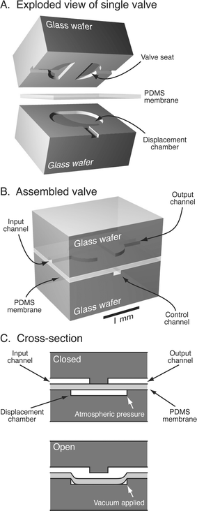 | ||
| Fig. 1 Monolithic membrane valve structure before, A, and after, B, bonding the wafers together with the PDMS membrane. Valves consist of a discontinuity in a channel (valve seat) directly across the PDMS membrane from an etched displacement chamber. C, Lengthwise cross-section through a valve. Valves are normally closed against low pressures in the valved channels; applying a vacuum to the displacement chamber via the “control” channel pulls the membrane into the displacement chamber and opens the valve. | ||
|
|
|||
|---|---|---|---|
| Rule | Maintained at input/kPa | Maintained at control/kPa | Measured at output/kPa |
| PP | 40 | 40 | 0 |
| PV | 40 | −85 | 40 |
| PN | 40 | 0 | 40 |
| VP | −85 | 40 | 0 |
| VV | −85 | −85 | −83 |
| VN | −85 | 0 | 0 |
In this work, we present and characterize several useful applications of pneumatic logic structures that exploit the capabilities of our monolithic membrane valves. Simple three- and four-valve networks are developed which function as latching valves. These valves maintain their open or closed state even after all sources of vacuum and pressure are removed from the device. Principles of pneumatic logic are then used to fabricate and test an on-chip valve-based demultiplexer that distributes millisecond duration vacuum and pressure pulses to set the latching valves open and closed. Using pneumatic logical structures, n off-chip pressure/vacuum pneumatic control lines are used to control 2(n−1) independent latching valves. These pneumatic logic structures are immediately valuable because they reduce or eliminate off-chip controllers. We anticipate that the operation of complex lab-on-a-chip devices could be programmed into and controlled by such on-chip pneumatic logical structures.
2 Methods
Latching valve device concept
Fig. 2 depicts a three-valve circuit that forms a vacuum-latching (“V-latching”) pneumatic valve. The control for the latching valve is connected to two additional valves, a vacuum valve (responsible for holding the latching valve open by sealing a vacuum on-chip via Rule VV) and a pressure valve (responsible for eliminating the sealed on-chip vacuum via Rule PN). The resulting circuit holds the valve open or closed after a short vacuum or pressure pulse is applied to the “set pulse input” channels. The related pressure/vacuum-latching (“PV-latching”) valve uses trapped vacuum to hold the latching valve open and trapped pressure to hold the valve closed against a wider range of fluid pressures.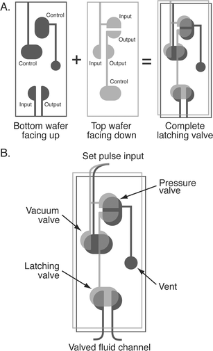 | ||
| Fig. 2 A, Assembly of the latching valve structures. B, Design of a completed latching valve, including the vacuum and pressure valves that impart latching behavior to the valve. | ||
In the V-latching valve shown in Figs. 2 and 3A, pulses of pressure and vacuum in the “set pulse input” channels are connected to the input of a pressure valve and the input and control of a vacuum valve. Since these valves are actuated by and operate upon pressurized and depressurized air, the usual references to fluidic and pneumatic connections5 have been discarded in favor of the input, control and output connections illustrated in Table 1. The pressure, vacuum, and latching valves are normally closed (step 1 in Fig. 3A). When a pulse of vacuum is applied to the “set pulse input” in step 2, the vacuum valve opens (Rule VV in Table 1) and the pressure valve remains closed (Rule VN). The latching volume (the channel volume containing the outputs of the pressure and vacuum valves and the control of the latching valve) is depressurized, and the latching valve opens. In less than 120 ms, when the latching volume has been depressurized to approximately 98% of the set input vacuum, the vacuum valve closes automatically (Step 3). When the set input vacuum pulse is removed in Step 4, the latching volume is sealed under vacuum by the pressure and vacuum valves according to Rule VN, and the latching valve will remain latched open as long as adequate vacuum remains in the latching volume.
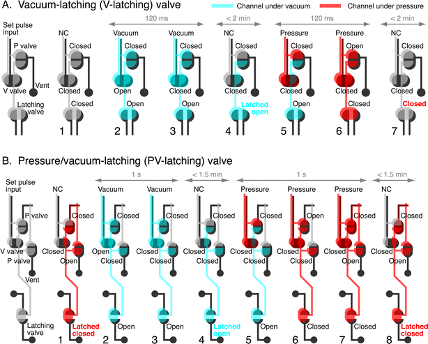 | ||
| Fig. 3 Design and operation of the V-latching, A, and PV-latching, B, valve pneumatic circuits. Both circuits contain the actual latching valve and two or three additional pneumatic logic valves. In the V-latching valve, 120 ms vacuum pulses (−85 kPa relative to atmospheric) applied to the “set pulse input” channels depressurize the latching volume and open the latching valve in Step 4. Pressure pulses (120 ms, 40 kPa relative to atmospheric) eliminate the vacuum in the latching volume and close the latching valve in step 7. “NC” indicates that no connection (only atmospheric pressure) is applied to the “set pulse input” channels. The PV-latching valve opens in a manner similar to the V-latching valve but traps pressure in the latching volume during closure (step 8); this pressure seals the latching valve closed against fluid pressures as high as 17 kPa. Gray arrows show typical amounts of time for the specified steps. | ||
To close the V-latching valve in Fig. 3A, a pulse of pressure is applied to the “set pulse input” in step 5. Within 120 ms, this pressure forces the pressure valve open according to Rule PN in step 6, and the now-pressurized latching volume seals the latching valve shut. When the set input pressure pulse is removed in step 7, the pressure in the latching volume escapes as the pressure valve closes. With no pressure in the latching volume to hold it closed, the latching valve can hold off fluid pressures up to 4 kPa without leakage.
The PV-latching valve shown in Fig. 3B can hold off larger fluid pressures because the latching volume is pressurized while the valve is latched shut (step 1 in Fig. 3B). The PV-latching valve is modeled after the V-latching valve but includes a second pressure valve, with its input connected to the latching volume, its output connected to the control of the first pressure valve, and its control connected to the atmosphere. In Steps 2 through 4, a pulse of vacuum opens the PV-latching valve in a manner similar to the V-latching valve; the second pressure valve remains closed because of Rule VN. To close the PV-latching valve, a pressure pulse is applied to the “set pulse input” in step 5. Within 1 s, this pressure forces open the first pressure valve by Rule PN in step 6, then forces open the second pressure valve by Rule PN in step 7. With the latching volume and the control for the first pressure valve all pressurized, the first pressure valve closes according to Rule PP. When the set input pressure is removed in Step 8, the pressure in the latching volume actively holds the first pressure valve closed and pressure is maintained in the latching volume, thereby holding the PV-latching valve shut against fluid pressures up to 17 kPa without leakage.
Device fabrication
Device features were etched into glass wafers using conventional photolithography and wet chemical etching.22 Briefly, 1.1 mm thick, 100 mm diameter borosilicate glass wafers were coated with 200 nm of polysilicon using low-pressure chemical vapor deposition. The wafers were then spincoated with positive photoresist, soft-baked, and patterned with the device design using a contact aligner and a chrome mask. After development and removal of irradiated photoresist, the exposed polysilicon regions were removed by etching in SF6 plasma and the exposed regions of glass were etched isotropically in 49% HF to a depth of 50 µm. After stripping the remaining photoresist and polysilicon layers, the wafers were diamond drilled with 500 µm diameter holes for pneumatic and fluidic connections. The wafers were then scored and broken, and the resulting layers were bonded together using a 254 µm thick PDMS elastomer membrane.5 Optionally, two or more etched or drilled glass wafers can be thermally bonded together prior to PDMS bonding; the resulting devices contain all-glass fluid layers that minimize fluid-PDMS contact.Valve characterization measurements
The latching valve structures were characterized using variable-duration pressure (40 kPa) and vacuum (−85 kPa) pulses from a computer-controlled solenoid valve. The pressures reported are relative to atmospheric pressure and were measured using a strain gauge pressure transducer. Flow rates through latching valves were measured by connecting a variable-height column of water to the input of the latching valve. The valve output was then connected to a short piece of hypodermic tubing suspended in a vial of water on an analytical balance with 1 mg (1 µL) precision. The mass of water flowing through the valve per unit time was used to determine the volumetric rate of flow through the valve and, in turn, the open or closed state of the valve against the applied fluid pressure.3 Results
Latching valve characterization
To test the function of the latching valve structure, fluid flow through a latching valve was measured while pressure and vacuum pulses of varying durations were used to actuate the valve. In the first trace in Fig. 4A, 60 s of constant vacuum or pressure was applied to hold the vacuum-latching valve open or closed. In subsequent traces, shorter pulses of vacuum and pressure were used to latch the valve open or closed. The similarity of the traces indicates that latching valves behave identically to constant vacuum/pressure valves, with only 120 ms vacuum/pressure pulses required to reliably actuate the latching valve. Shorter pulses (80 ms) still opened the latching valve reliably but were too brief for reliable closure.To determine the long-term stability of a valve latched open or closed, flow through a latched valve was measured for ten minutes. The first trace in Fig. 4B shows that a 120 ms pressure pulse is adequate to latch a V-latching valve closed for at least ten minutes. The second trace indicates that a 120 ms vacuum pulse latches a V-latching valve open for two minutes before the flow rate through the valve decreases by 10%. Owing to the gas permeability of the PDMS membrane, a gradual loss of vacuum in the latching volume slowly closes the latching valve and decreases the flow rate further over the next eight minutes.
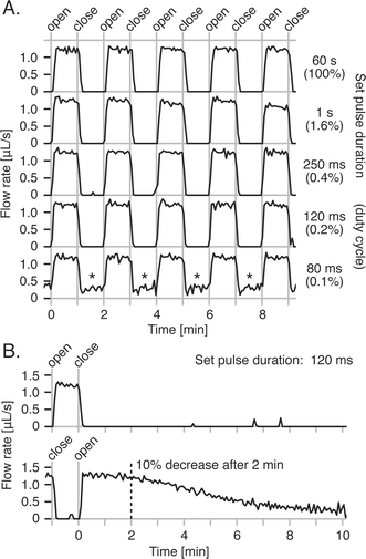 | ||
| Fig. 4 A, Flow rates through a V-latching valve being set open and closed by vacuum and pressure pulses of varying durations. Pulses as short as 120 ms (only 0.2% duty cycle) are adequate for reliable valve actuation; shorter pulses still open the valve but cannot close it against the 4 kPa fluid pressure (asterisks). B, Flow rates through the same V-latching valve after being latched closed or open by a 120 ms pressure or vacuum pulse. The valve remains closed against the 4 kPa fluid pressure for at least 10 min with only minimal leakage, and open for at least 2 min before the flow rate through the valve decreases by 10%. | ||
The pressure/vacuum-latching valve design in Fig. 3B pressurizes the latching volume to hold the valve closed against high fluid pressures. To confirm this behavior, V- and PV-latching valves were fabricated with drilled holes for measuring the pressure inside the latching volumes during valve actuation. The pressure inside the latching volume was measured while 10 s pressure and vacuum pulses were used to actuate the valve (see electronic supplementary information†). While both valve designs retained vacuum (−60 kPa) in the latching volumes following the vacuum pulse, only the PV-latching valve retained pressure (8 kPa) after the pressure pulse.
To verify that the pressure retained in the PV-latching valve holds the valve closed against high fluid pressures, pressure-driven fluid flow through a PV-latching valve was measured while actuating the valve with 5 s pulses of vacuum and pressure. Fig. 5A shows that fluid pressures as high as 17 kPa were held off by the valve when latched closed; at 24 kPa, leakage of approximately 1 µL s−1 was detected through the closed valve. In Fig. 5B, the shortest pressure pulse required for reliable sealing against 17 kPa fluid pressure was found to be 1 s. This is considerably longer than the 120 ms pulse required to close the V-latching valve, probably because the two pressure valves must open in series via relatively-slow Rule PN before the latching volume is pressurized and sealed. Finally, Fig. 5C confirms that the long-term stability of latched open or closed PV-latching valves compares favorably with V-latching valves. A 5 s pressure pulse seals the PV-latching valve against 17 kPa fluid pressure for 7.5 min before flow through the valve rises to 10% of the open-valve flow rate. The second trace shows that a 5 s vacuum pulse holds the PV-latching valve open for 1.5 min before the flow rate drops by 10%.
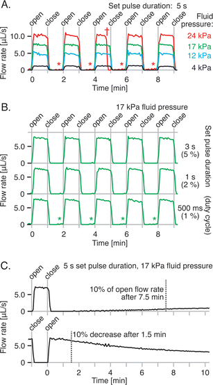 | ||
| Fig. 5 A, Flow rates through a PV-latching valve opening and closing against a range of fluid pressures. The PV-latching valve latches closed against fluid pressures as high as 17 kPa without detectable leakage; higher fluid pressures caused a small amount of leakage through the closed valve (asterisks). A premature valve closure observed only at the highest fluid pressure (dagger) was attributed to residual pressure trapped in the section of the pressure-latching volume between the pressure valves. This pressure leaked into the vacuum-latching volume while the valve was latched open, eliminating the trapped vacuum and closing the latching valve prematurely. B, Flow rates through the same PV-latching valve, using pressure/vacuum pulses of different durations to open and close the valve. C, Flow rates through the same PV-latching valve following 5 s pressure or vacuum pulses to hold the valve closed or open against 17 kPa fluid pressure. Leakage through the closed valve increases very slowly to about 10% of the open valve flow rate after 7.5 min. | ||
Demultiplexer design and operation
The four-bit binary demultiplexer shown in Fig. 6 addresses 24 or sixteen independent V-latching valves and distributes pressure and vacuum pulses to each of them in turn. A single “set pulse input” pressure/vacuum connection at the top of the device in Fig. 6A provides the pressure and vacuum required to actuate the latching valves. The demultiplexer contains four rows of monolithic membrane valves, with each row containing twice the number of valves of the previous row. Each row of valves in the demultiplexer is controlled by two pneumatic connections to a single off-chip 4/2 (four connection, two position) solenoid valve. The pneumatic connections are distributed on-chip in an alternating fashion to the demultiplexer valves in each row. For example, in the third demultiplexer row in Fig. 6, pneumatic connection “3L” controls demultiplexer valves 1, 3, 5, and 7 (numbered left to right), and pneumatic connection “3R” controls demultiplexer valves 2, 4, 6, and 8.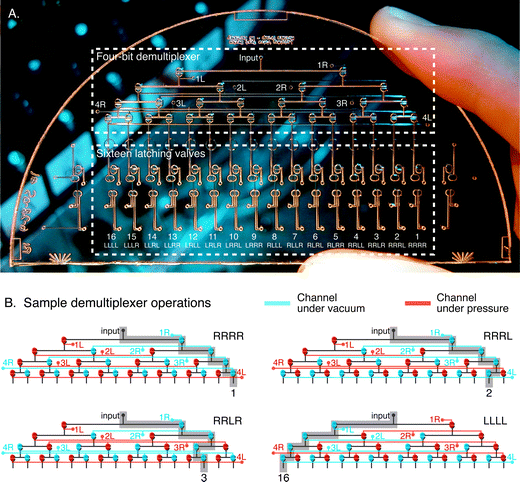 | ||
| Fig. 6 A, Photograph of the multiplexed latching valve test device, with a four-bit demultiplexer (top box) for routing pressure and vacuum pulses from the single “input” connection to each of sixteen latching valves (bottom box). B, Illustrations of the demultiplexer during four of the sixteen possible addressing operations. Each unique assignment of pressure and vacuum to the four rows of demultiplexer valves routes a single pressure/vacuum source at “input” to one of sixteen latching valves. The device can set a latching valve every 120 ms and set all sixteen valves to any arbitrary pattern every 2 s. | ||
When the solenoid valve controlling a particular row of demultiplexer valves is de-energized, pressure is applied to the odd-numbered demultiplexer valves and vacuum is applied to the even-numbered valves. The even-numbered valves open and “input” pressure or vacuum from the previous row is routed to the right into the next row of demultiplexer valves. When the solenoid valve is energized, pressure is applied to the even-numbered demultiplexer valves and vacuum is applied to the odd-numbered valves. The odd-numbered valves open and “input” pressure or vacuum is routed to the left into the next row of demultiplexer valves.
An n-bit demultiplexer is addressed by setting each of the n rows to route “input” pressure/vacuum to either the right or the left, and the 2n possible addresses range from “all right” to “all left” and every intermediate value. For n = 4, four of the sixteen possible addresses (RRRR, RRRL, RRLR, and LLLL) are illustrated in Fig. 6B. Each unique address routes the “input” pressure or vacuum to a different latching valve. By actuating the demultiplexing valves according to a cyclic pattern that selects each latching valve in turn, and applying vacuum or pressure to the “input” connection at the appropriate time to open or close the selected latching valve, the latching valves can be opened or closed according to any arbitrary pattern. In this manner, an n-row demultiplexer operated by n solenoid valves can address 2n independent latching valves.
Demultiplexer characterization
A CCD camera was used to record movies of the demultiplexer test device during operation. By cycling the demultiplexer valves through all sixteen addresses in the binary counting order RRRR, RRRL, RRLR, RRLL, RLRR, RLRL, RLLR, RLLL, LRRR, LRRL, LRLR, LRLL, LLRR, LLRL, LLLR, and LLLL, all sixteen latching valves are set in numerical order from 1 through 16 at a rate of 190 ms per step or 3 s per cycle. Fig. 7 presents a series of movie frames showing the open/closed state of each latching valve at each of the 32 steps in a single demultiplexer cycle. Open valves appear brighter than closed valves because the stretched valve membrane forms a concave surface and reflects additional light from a fiber optic illuminator into the CCD. In steps 1 through 16 vacuum is distributed to open valves 1 through 16 in turn, and in steps 17 through 32 pressure is distributed to close valves 1 through 16. Note that in this and subsequent demultiplexer studies, the state of valve three is intentionally negated, meaning that the demultiplexer must successfully route a single 190 ms pulse of pressure (step 4) during a series of 15 vacuum pulses, and a single 190 ms pulse of vacuum (step 20) during a series of 15 pressure pulses—an especially challenging operation for the demultiplexer.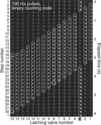 | ||
| Fig. 7 Video frames showing the multiplexed latching valve device (Fig. 6) in operation. The open/closed state of each of the sixteen latching valves is shown at each step in a 32-step cycle; open valves reflect more light and appear brighter than closed valves. A binary counting order was used to address the latching valves through the demultiplexer, with 190 ms pressure/vacuum pulses routed to each of the latching valves in turn. The observed and predicted open valves (white rectangles) at each step agree fairly well, with three errors (white ovals) attributed to demultiplexer malfunctions arising from deficiencies in the binary counting addressing code. The original video is available for download (see electronic supplementary information†). | ||
While the observed pattern of open valves in Fig. 7 closely matches the expected pattern (white rectangles), three errors were found (white ovals): valve 8 closed early with valve 7 in step 24, and valve 16 opened early with valve 15 in step 16 and closed early with valve 15 in step 32. Each of these errors involves a valve opening or closing early with the previous valve. Such errors occur when only the least significant bit of the demultiplexer is switching, suggesting a malfunction associated with the least significant row of valves. Closer examination of the binary counting pattern used to operate the demultiplexer revealed that the least significant bit of the demultiplexer switches with every step, causing the sixteen demultiplexer valves associated with this bit to open or close every 190 ms. Errors of only a few milliseconds in the actuation of these overwhelmed demultiplexer valves evidently cause the observed errors.
To lessen the repetitive strain on the least significant bit demultiplexer valves, the binary counting order was replaced by the Gray code23 order RRRR, RRRL, RRLL, RRLR, RLLR, RLLL, RLRL, RLRR, LLRR, LLRL, LLLL, LLLR, LRLR, LRLL, LRRL, and LRRR. This pattern sets the sixteen latching valves in the order 1, 9, 13, 5, 7, 15, 11, 3, 4, 12, 16, 8, 6, 14, 10, and 2 at a rate of only 120 ms per step or less than 2 s per cycle. Using this addressing order, demultiplexer valves are actuated at most every other step, or every 240 ms, compared with every 190 ms for the flawed binary counting order. The video frames in Fig. 8A show the open/closed state of each latching valve at each of the 32 steps in a single demultiplexer cycle that opens each valve in steps 1 through 16 and closes each valve in steps 17 through 32 (with valve 3 still inverted). The observed pattern of open valves exactly matches the expected pattern (white rectangles) with no errors, proving that the demultiplexer can accurately route pressure and vacuum pulses as short as 120 ms to the intended latching valves.
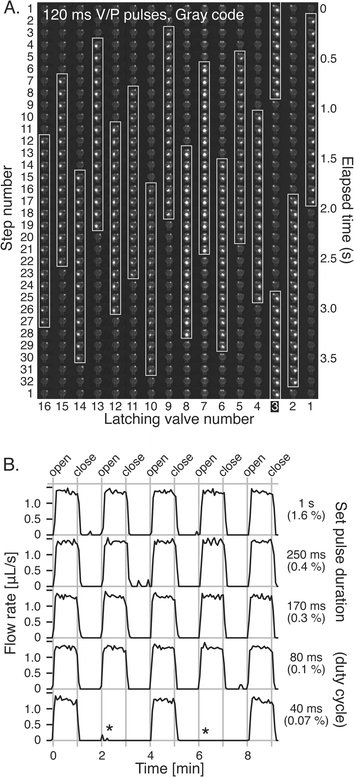 | ||
| Fig. 8 A, Video frames showing the multiplexed latching valve test device in operation, using an improved Gray code order for operating the demultiplexer and only 120 ms pressure/vacuum pulses. The observed open valves matched the expected open valves (white rectangles) with no errors. B, Flow rates through inverted latching valve 3, obtained while operating all sixteen latching valves according to the complex actuation pattern shown in A. Pressure and vacuum pulses as short as 80 ms (0.1% duty cycle) were adequate to open and close the valve without errors. Missed openings observed at even shorter pulse times (asterisks) are caused by demultiplexer timing errors. The original video is available for download (electronic supplementary information†). | ||
In addition to confirming the operation of the demultiplexed latching valves visually, the ability of the demultiplexed valves to control fluid was also demonstrated. Fig. 8B presents the flow of fluid through the inverted valve 3 while all sixteen latching valves were being actuated according to the complex pattern in Fig. 8A. Pressure and vacuum pulses as short as 80 ms were adequate to open and close the inverted valve 3. Shorter pulses occasionally failed to open the valve, probably because of demultiplexer timing errors at fast actuation rates.
4 Discussion
We have developed and characterized a latching pneumatic valve design suitable for high-density integration into lab-on-a-chip devices. By eliminating the need for a separate off-chip controller for each independent valve or parallel array of valves on-chip, the latching pneumatic valves presented here make large-scale control of independent valves feasible. The vacuum-latching valves can control on-chip fluid flow in a variety of assays involving low (<4 kPa) fluid pressures, and the pressure/vacuum-latching valves close reliably against fluid pressures up to 17 kPa. Latching valves retain the low (∼10 nL) dead volumes found in monolithic membrane valves.5 Since the latching structures presented here consist of monolithic membrane valves that can be operated continuously for hours and for tens of thousands of actuations without failure,20,21 we anticipate that the long-term durability of these structures will be very favorable. Our latching valve structures depend upon the normally-closed nature of membrane valves.5 Rules PN (input pressure breaking through an unpowered valve), VN (input vacuum sealing an unpowered valve), and VV (a valve opening to evacuate a volume on-chip, then closing automatically to seal the volume under vacuum), all of which are essential to the operation of the latching valves, would be difficult or impossible to replicate using normally-open PDMS valves.4We have also presented a valve-based pneumatic demultiplexer for controlling large arrays of independent latching valves. The demultiplexer uses only n off-chip pneumatic inputs to control 2(n−1) multiplexed latching valves. In this example, sixteen independent latching valves can be set in any arbitrary pattern every two seconds using only five pneumatic controls. The multiplexed latching valves retain their ability to independently control fluid flow. Since the pressure, vacuum, and demultiplexer valves that operate the latching valves never contact the valved fluid, the potential for cross-contamination between multiplexed latching valves is eliminated. Existing methods of on-chip logic using normally-open valves have proved to be very useful in addressing rectilinear arrays of microreactors6 but have not been applied to the arbitrary control of independent latching valves as presented here.
What is the upper limit for large-scale control using the multiplexed latching valves developed here? Vacuum and pressure pulses as short as 120 ms (8 valves per second) were found to be adequate to hold the V-latching valves open and closed for at least two minutes. In two minutes, 1000 independent latching valves can be set at a rate of 8 valves per second. This massive number of valves would require (log21000) + 1 or only 11 off-chip pneumatic controls! The 10-bit demultiplexer would contain 210+1 − 2 or 2046 valves, and each of the 1000 V-latching valves would require two logic valves, for a total of 4046 on-chip logic valves to control 1000 latching valves. If each logic valve and its associated pneumatic channels occupy 2 mm2, 4000 logic valves could be fabricated using photolithography into a single glass–PDMS–glass layer of a 10 cm diameter microfluidic device. One surface of this layer could then be bonded to additional glass wafers through another PDMS membrane, thereby forming a fluidic layer for the placement of the 1000 independent latching valves in the desired assay configuration. The prospect that a single additional layer in a lab-on-a-chip device could eliminate literally hundreds of off-chip solenoid valves, relays, and computers attests to the potential of pneumatic logical structures.
By reducing the off-chip control equipment necessary for the operation of microfluidic devices, multiplexed latching pneumatic valves should play an especially important role in making low-cost, low-power, and hand-held lab-on-a-chip analysis devices a reality. Analysis devices with fewer off-chip solenoid valves and electronic control circuits would consume less power and be better suited for battery-operated field use. Critically, in robotic analysis systems for space exploration,16 eliminating off-chip controllers would conserve sparse payload space and power. We also note that pneumatic logic circuits like the demultiplexer presented here are immune to high energy particles, solar flares, and electromagnetic pulse interference, which can irreparably damage electronic logic circuits.24
The technology presented here also establishes the basis for pneumatic logic gates—generic, valve-based AND, OR, and NOT structures—which can be arranged into circuits or programs that encode and control the operation of any microfluidic device. In a classic example, flow through two valves connected in series is allowed only if both valves are open—a logical AND. Similarly, flow through two valves connected in parallel is possible if either (or both) of the valves is open—a logical OR. The feedback loops used to hold the latching valve open in the V-latching valve and closed in the PV-latching valve are closely analogous to NAND- and NOR-based latch circuits used as binary memories in electronic circuits.8 These logical operations form the foundations of all electronic computations. We anticipate that microfluidic logic structures of the type presented here will similarly prove to be fundamentally useful in the assembly of complex pneumatic microprocessors.
Acknowledgements
Device fabrication was performed in the University of California, Berkeley Microfabrication Laboratory. This research was supported by donations from Affymetrix to the Berkeley Center for Analytical Biotechnology.References
- D. J. Harrison, K. Fluri, K. Seiler, Z. H. Fan, C. S. Effenhauser and A. Manz, Micromachining a miniaturized capillary electrophoresis-based chemical-analysis system on a chip, Science, 1993, 261, 895–897 CrossRef CAS.
- C. A. Emrich, H. J. Tian, I. L. Medintz and R. A. Mathies, Microfabricated 384-lane capillary array electrophoresis bioanalyzer for ultrahigh-throughput genetic analysis, Anal. Chem., 2002, 74, 5076–5083 CrossRef CAS.
- E. T. Lagally, J. R. Scherer, R. G. Blazej, N. M. Toriello, B. A. Diep, M. Ramchandani, G. F. Sensabaugh, L. W. Riley and R. A. Mathies, Integrated portable genetic analysis microsystem for pathogen/infectious disease detection, Anal. Chem., 2004, 76, 3162–3170 CrossRef CAS.
- M. A. Unger, H. P. Chou, T. Thorsen, A. Scherer and S. R. Quake, Monolithic microfabricated valves and pumps by multilayer soft lithography, Science, 2000, 288, 113–116 CrossRef CAS.
- W. H. Grover, A. M. Skelley, C. N. Liu, E. T. Lagally and R. A. Mathies, Monolithic membrane valves and diaphragm pumps for practical large-scale integration into glass microfluidic devices, Sens. Actuators, B, 2003, 89, 315–323 CrossRef.
- T. Thorsen, S. J. Maerkl and S. R. Quake, Microfluidic large-scale integration, Science, 2002, 298, 580–584 CrossRef CAS.
- J. P. Urbansky, W. Thies, C. Rhodes, S. Amarasinghe and T. Thorsen, Digital microfluidics using soft lithography, Lab Chip, 2006, 6, 96–104 RSC.
- C. H. Roth, Jr., Fundamentals of logic design, West Publishing Company, 1985 Search PubMed.
- B. Wagner, S. Hoerschelmann, H. J. Quenzer, T. Lisec and M. Juerss, Bistable microvalve with pneumatically coupled membranes inProceedings of the Ninth Annual IEEE International Workshop on Micro Electro Mechanical Systems, IEEE, New York, 1996, pp. 384–388 Search PubMed.
- C. Goll, W. Bacher, B. Bustgens, D. Maas, W. Menz and W. K. Schomburg, Microvalves with bistable buckled polymer diaphragms, J. Micromech. Microeng., 1996, 6, 77–79 CrossRef CAS.
- J. A. Potkay and K. D. Wise, An electrostatically latching thermopneumatic microvalve with closed-loop position sensing, in Proceedings of the 18th IEEE International Conference on Micro Electro Mechanical Systems, IEEE, New York, 2005, pp. 415–418 Search PubMed.
- J. Y. Pan, D. VerLee and M. Mehregany in Latched valve manifolds for efficient control of pneumatically actuated valve arrays in Proceedings of the IEEE International Conference on Solid State Sensors and Actuators, 1997, pp. 817–820 Search PubMed.
- S. Bohm, G. J. Burger, M. T. Korthorst and F. Roseboom, A micromachined silicon valve driven by a miniature bi-stable electro-magnetic actuator, Sens. Actuators, A, 2000, 80, 77–83 CrossRef.
- M. Capanu, J. G. Boyd and P. J. Hesketh, Design, fabrication, and testing of a bistable electromagnetically actuated microvalve, J. Microelectromech. Syst., 2000, 9, 181–189 CrossRef CAS.
- R. Pal, M. Yang, B. N. Johnson, D. T. Burke and M. A. Burns, Phase change microvalve for integrated devices, Anal. Chem., 2004, 76, 3740–3748 CrossRef CAS.
- A. M. Skelley, J. R. Scherer, A. D. Aubrey, W. H. Grover, R. H. C. Ivester, P. Ehrenfreund, F. J. Grunthaner, J. L. Bada and R. A. Mathies, Development and evaluation of a microdevice for amino acid biomarker detection and analysis on Mars, Proc. Natl. Acad. Sci. U. S. A. , 2005, 102, 1041–1046 CrossRef CAS.
- J. M. Karlinsey, J. Monahan, D. J. Marchiarullo, J. P. Ferrance and J. P. Landers, Pressure injection on a valved microdevice for electrophoretic analysis of submicroliter samples, Anal. Chem., 2005, 77, 3637–3643 CrossRef CAS.
- E. T. Lagally, S. H. Lee and H. T. Soh, Integrated microsystem for dielectrophoretic cell concentration and genetic detection, Lab Chip, 2005, 5, 1053–1058 RSC.
- R. G. Blazej, P. Kumaresan and R. A. Mathies, Microfabricated bioprocessor for integrated nanoliter-scale Sanger DNA sequencing, Proc. Natl Acad. Sci. U. S. A. Search PubMed , in press.
- B. M. Paegel and G. F. Joyce, Microfluidic serial transfer circuit: Automated evolution of RNA catalysts, in K. F. Jensen, J. Han, D. J. Harrison and J. Voldman, eds., Proceedings of the MicroTAS 2005 Conference, Boston, MA, USA, October 9–13, 2005, pp. 28–30 Search PubMed.
- W. H. Grover and R. A. Mathies, An integrated microfluidic processor for single nucleotide polymorphism-based DNA computing, Lab Chip, 2005, 5, 1033–1040 RSC.
- P. C. Simpson, D. Roach, A. T. Woolley, T. Thorsen, R. Johnston, G. F. Sensabaugh and R. A. Mathies, High-throughput genetic analysis using microfabricated 96-sample capillary array electrophoresis microplates, Proc. Natl. Acad. Sci. U. S. A., 1998, 95, 2256–2261 CrossRef CAS.
- W. H. Press, S. A. Teukolsky, W. T. Vetterling and B. P. Flannery, Numerical Recipes in C: The Art of Scientific Computing, Cambridge University Press, 1992 Search PubMed.
- D. M. Fleetwood, P. S. Winokur and P. E. Dodd, An overview of radiation effects on electronics in the space telecommunications environment, Microelectron. Reliab., 2000, 40, 17–26 CrossRef.
Footnotes |
| † Electronic supplementary information (ESI) available: pressure inside the latching volume, videos of the multiplexed latching valve test device in operation using binary and Gray addressing codes. See DOI: 10.1039/b518362f. |
| ‡ Biophysics Graduate Group, UC Berkeley. |
| This journal is © The Royal Society of Chemistry 2006 |

