Isolation of plasma from whole blood using planar microfilters for lab-on-a-chip applications
Timothy A.
Crowley†
and
Vincent
Pizziconi
*
Harrington Department of Bioengineering, Arizona State University, P.O. Box 879709, Tempe, AZ 85287-9709, USA. E-mail: vincent.pizziconi@asu.edu; Tel: (480) 965-1071; Fax: (480) 727-7624
First published on 19th July 2005
Abstract
Researchers are actively developing devices for the microanalysis of complex fluids, such as blood. These devices have the potential to revolutionize biological analysis in a manner parallel to the computer chip by providing very high throughput screening of complex samples and massively parallel bioanalytical capabilities. A necessary step performed in clinical chemistry is the isolation of plasma from whole blood, and effective sample preparation techniques are needed for the development of miniaturized clinical diagnostic devices. This study demonstrates the use of passive, operating entirely on capillary action, transverse-flow microfilter devices for the microfluidic isolation of plasma from whole blood. Using these planar microfilters, blood can be controllably fractionated with minimal cell lysis. A characterization of the device performance reveals that plasma filter flux is dependent upon the wall shear rate of blood in the filtration channel, and this result is consistent with macroscale blood filtration using microporous membranes. Also, an innovative microfluidic layout is demonstrated that extends device operation time via capillary action from seconds to minutes. Efficiency of these microfilters is approximately three times higher than the separation efficiencies predicted for microporous membranes under similar conditions. As such, the application of the microscale blood filtration designs used in this study may have broad implications in the design of lab-on-a-chip devices, as well as the field of separation science.
1 Introduction
Microfabrication technology, originally developed for very large-scale integrated circuits, stimulated a plurality of lab-on-a-chip research and development efforts aimed at enabling biomedical researchers and health care practitioners to manipulate and analyze complex biological fluids at the nano and microliter scale. The development of miniaturized diagnostic devices for the clinical analysis of blood and other body fluids is an important application of this emerging technology.1–6 The potential advantages of this new technology over conventional clinical diagnostic instrumentation are significant. The traditional clinical diagnostic laboratory is a centralized facility equipped with bulky, automated equipment that requires extensive investment of skilled labor, milliliter-scale sample and reagent volumes, and delivers turn-around-times of hours to days. In contrast, miniaturized blood analysis devices can increase diagnostic capacity significantly by enabling rapid, point-of-care chemical analysis requiring only nanoliter sample and reagent volumes, thereby reducing cost and turn-around time.4 For example, the cost/benefit potential of miniaturized clinical chemistry technology to directly improve patient care and related health care delivery methods has already been demonstrated with point-of-use blood glucose monitoring systems.7,8 Similar benefits are expected with the development of highly integrated lab-on-a-chip devices with the capability to measure multiple analytes from a single drop of blood.Current clinical chemistry technologies require ‘upstream’ sample preparation when performing analysis on complex biological samples. For example, clinical chemists use centrifugation or sedimentation to first isolate plasma from whole blood, because blood cells and hemoglobin interfere with analytical chemistries relying on optical measurement techniques. Microdevices can be engineered with an integrated plasma isolation process directly upstream of the analyte detection system thus permitting direct sample delivery capability, e.g. one step blood analysis from a finger stick. For miniaturized point-of-care applications, blood separation strategies must avoid significant cell lysis, occupy a small operational footprint, produce adequate plasma volumes in a short time frame, enable large-scale integration and portability, and possess design features compatible with prevailing fabrication methods. In the current point-of-care devices, such as the glucose test strip, plasma is isolated from whole blood using glass fiber filters or microporous membranes;9 however, these filtration technologies are not easily integrated with microfabrication strategies employing complex arrays of microfluidic channels. Although researchers have recently reported many lab-on-a-chip diagnostic advances, only a few results relevant to the microfluidic fractionation of blood are reported.10 For example, Brody et al.11 first suggested the separation of plasma from whole blood using a microfabricated filter device, and reported the filtration of a suspension of microspheres. Wilding et al.12 demonstrated the use of microfilters to capture white blood cells for genetic analysis, and Duffy et al.13 proposed the use of centrifugation on a rotating “lab disc”. Most recently Moorthy and Beebe14 filtered a suspension of red blood cells using on-chip microporous membranes, fabricated using an in situ emulsion photo-polymerization technique.
Microfilter designs are well suited for microfluidic blood sample preparation. The microfilter structures are compatible with current microfabrication technologies, and filtration can be accomplished via capillary action. Additionally, the precise dimensional and geometric control afforded by micromachining may enable the development of optimum filter designs that are not possible with traditional membrane filtration. For example, microfabrication techniques can form complex geometric structures at length scales that are not possible in macroscale filtration. Hollow fiber membranes commonly used for plasmapheresis have bulk flow channel diameters of 200 to 400 μm, while microfluidic channels are readily constructed at dimensions commensurate with blood cells. Also, microfilter devices can be fabricated with precise pore dimensions and geometry, while pore sizes and shapes in microporous membranes are commonly heterogeneous and difficult to characterize. Finally, planar microfilter devices fabricated with optically transparent glass or plastic enable direct microscopic observation of the filtration process on a cellular level and may lead to an improved understanding of the filtration process.
In this research, transverse-flow microfilters (blood flow is parallel to the filter face) were micromachined in silicon and glass substrate materials, and used to study the engineering variables controlling the ‘on-chip’ separation of plasma from whole blood. The effects of blood shear rate and red blood cell volume fraction (hematocrit) on plasma filter flux were investigated and compared to well-known macroscale blood filtration results using microporous membranes.15,16 Similar to macroscale plasmapheresis operations, filter flux in these microdevices conforms to a power law model, with filter flux as a function of the wall shear rate of blood in the filtration channel. Unlike macroscale operations, microfilter plasma flux was insensitive to hematocrit levels between ∼20 and 40%. Additionally, an innovative microfluidic design layout is demonstrated that extends the operational time of these microfilters from seconds to minutes.
2 Background
The development of microfilter devices for on-chip blood separation utilizing capillary action spans several key disciplines: separation science, fluid mechanics, and hemorheology. In this background section, we provide a short review of the critical concepts in each area that are particularly relevant to microfilter designs for blood separation.2.1 Membrane fractionation of blood
For liquids, membrane-based separation processes have been used to separate, concentrate, purify, and harvest dissolved solids, particulates, and cells. These processes have been investigated extensively with applications ranging from the desalination of seawater to blood separation.17,18 In order to maximize yield or reduce processing time, membrane filtration is commonly performed with flow parallel to the filter, referred to as transverse or cross flow filtration, as illustrated in Fig. 1 for blood separation. This approach produces high separation efficiencies by reducing the accumulation of fouling elements, such as red blood cells, at the filter face. | ||
| Fig. 1 Microporous membrane filtration of whole blood utilizing cross flow filtration. | ||
Extensive research has been reported for macroscale blood separation using microporous membranes for extracorporeal artificial organ and therapeutic applications.15,16,19–28 These studies provide numerous engineering filtration and hemolysis models that may also be applied to the study of microfluidic blood separation techniques.
Plasmapheresis researchers identified hematocrit, transmembrane pressure, and wall shear rate as the key operating variables controlling plasma filter flux during blood separation with microporous membranes. In these separations, higher levels of hematocrit increase filter fouling and reduce flux. Transmembrane pressure initially causes a rapid increase in flux but quickly reaches a pressure-independent equilibrium due to the accumulation of red blood cells at the filter face. In this pressure independent range, wall shear rate is the primary modulator of plasma flux, with greater levels of shear rate increasing plasma flux. Shear rate affects flux by modulating the thickness of the red cell fouling layer at the filter face through transport effects such as shear-enhanced diffusion.
Mass transport models for plasma flux through the filter have been proposed and validated by numerous plasmapheresis studies.16,20,29 Although the physics of the models differed, each relates filter flux to wall shear rate as
| Jf = Kγnw | (1) |
Additionally, these plasmapheresis models may be used to compare microfilter and macroscale performance. In this paper, we compared microfilter performance to predictions made using the concentration polarization model of Zydney and Colton,15 shown below
 | (2) |
These models relating flux and wall shear rate provide a fundamental starting point for microfilter development and the design of experimentation intended to elucidate the critical process parameters governing microfluidic blood fractionation. An investigation into the effects of shear rate on microfilter plasma flux is a key focus of this report.
2.2 Fluid mechanics for capillary action in microfilter designs
The unique surface to volume ratio of microfluidic channels permits engineering design strategies that are unattainable at the macroscale. For example, capillary action can be utilized to produce fluid flow in lab-on-a-chip devices for meaningful periods of time without a power-supply, moving parts, or external energy. Since effective miniaturized pumping strategies applicable to lab-on-a-chip devices remain poorly established, the ability to motivate fluids using surface energy alone should be exploited in microfluidic designs. However, a requisite to effectively utilizing capillary action is the development of design strategies that can maintain stable fluid flow for useful periods of time. To evaluate potential microfilter configurations, we utilized the Washburn equation,30 shown below for a wide rectangular channel (eqn. (3)), to perform preliminary design assessments. | (3) |
This equation may be used to predict capillarity-driven flow over time. It is a quasi-steady state model derived from Poiseuille's equation, where L is the length of fluid, ΔP is the driving force (i.e., capillarity), μ is the fluid viscosity, t equals time, and h is the channel half height. To apply the Washburn model, the apparent capillary pressure is calculated using the Young–Laplace equation, shown below for rectangular channels,
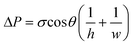 | (4) |
The Washburn equation may also be expressed as average flow velocity, uavg, as a function of time, eqn. (5).
 | (5) |
From eqn. (5) one can see that flow velocity in a straight channel decays as an inverse function of time. For a straight channel of uniform dimensions with a length scale pertinent to microfluidic devices—several centimeters long and ∼10 to 20 µm deep—flow times of aqueous solutions are relatively short, on the order of ∼10 s. However, analysis of a more complex geometry, employing a narrow channel and a wide channel connected in series (Fig. 2 inset), suggested it is possible to produce extended passive flow time, and a more ‘steady-state’ average velocity in the narrow channel compared to a straight channel of equivalent length (Fig. 2). In this arrangement, the larger expanded channel provides a large surface area for capillary wetting, and the narrow channel limits the overall flow rate. The net result is a device with significantly longer flow duration than a single channel. Also, key engineering parameters, such as shear rate, may be manipulated over a wide range by adjusting the length of the narrow channel and the relative cross-sectional areas of the narrow and expanded channels. Additionally, fluidic models of this configuration indicate that it produces more steady state flow behavior in the narrow channel, as shown in Fig. 2. This characteristic can facilitate and simplify the study of the engineering variables controlling microfilter blood separation processes.
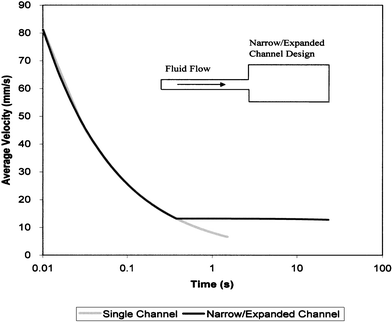 | ||
| Fig. 2 Theoretical comparison of capillarity-driven average velocity for a Newtonian liquid in two different microfluidic designs; a single uniform flow channel and a narrow/expanded channel layout (inset) with equivalent channel heights and total length. Utilizing the narrow/expanded channel design, duration of the flow may be significantly extended compared to a single narrow channel. | ||
2.3 Blood rheology
Blood is a uniquely complex fluid composed of deformable blood cells in an aqueous solvent containing colloids, such as proteins, small molecules, and lipids among other constituents. Blood typically contains 40 to 50% cells by volume (hematocrit). Red blood cells make up approximately 95% of all cells, and have a biconcave shape ∼3 microns thick and 8 microns in diameter for human red blood cells. Blood exhibits non-Newtonian rheological characteristics—unrelated to coagulation or clotting—as the apparent viscosity of blood decreases with increasing shear-rate, i.e., as blood flows more quickly the apparent viscosity decreases, an effect known as shear-thinning.31 The deformability of red cells and their interaction with select plasma proteins is responsible for blood's non-Newtonian characteristics. At shear rates below ∼50 s−1, the apparent viscosity of blood increases exponentially due to a reversible aggregation of red cells known as rouleaux formation. As shear rate increases above ∼50 s−1, the shear field disrupts cell aggregation, and causes red cell deformation resulting in an ∼100-fold decrease in apparent viscosity over the low shear rate regime. Beyond shear rates of 100–300 s−1, blood viscosity approaches Newtonian behavior with typical values of 3 to 4 cP. This apparent limiting viscosity is a function of the blood composition, and is primarily modulated by hematocrit.While the non-Newtonian characteristics of blood can complicate microfluidic modeling, a number of rheological models exist that permit the estimation of blood flow characteristics over a wide range of conditions.31–33 However, an alternative approach is to develop device designs that produce primarily Newtonian like behavior, i.e. maintain average shear rates at levels above ∼100–300 s−1, and avoid the onset of this non-Newtonian behavior. In this research, microfilter test devices were designed to maintain a minimum level of shear rate in an effort to avoid the onset of high apparent viscosity induced by the aggregation of cells in low shear rate flow fields.
3 Materials and methods
Blood filtration experiments were conducted with passive microfilter devices fabricated in silicon and glass wafers using photolithography and reactive ion etching. The design layout incorporated a narrow/expanded channel design to produce extended operation time via capillary action (Fig. 2 inset). Three different test devices were designed to produce varying levels of blood wall shear rate at the microfilter. Filtration testing was performed using anticoagulated, whole bovine blood. Video microscopy and digital video analysis was utilized to study and quantify blood flow rate, the plasma volume extracted, and evaluate plasma for the presence of free hemoglobin.3.1 Microfilter device design
The generic microfilter design consisted of an input reservoir, narrow filtration channel with transverse flow microfilter, a plasma outlet channel to collect filtered plasma, and a wider expanded channel connected in series with the filtration channel (Fig. 3). Flow channels were 10 µm deep, and the filtration channel was 100 µm wide. The expanded channel areas were fabricated as arrays of parallel flow channels, 45 µm wide, and 15 mm long. Using Newtonian fluid flow models, employing an assumed apparent limiting viscosity of blood, the total width of the expanded channel was designed proportionally with the filtration channel length and area to maintain an average expanded channel wall shear rate of blood greater than 100 s−1, i.e. the design intended to avoid very low shear rates conditions in the expanded channels that would result in high apparent blood viscosities. | ||
| Fig. 3 Microfilter device design and detail: (a) top view of generic device design with narrow and expanded channels, (b) filter detail area showing filter pores and expanded channel layout, (c) microfilter cross section. | ||
The filter was fabricated as a series of rectangular openings, “pores”, placed on both sides of the filtration channel (see Fig. 3b). The filter pores were 200 μm wide, 0.5 μm high, and 50 μm long. The cumulative length of the filter pores was approximately 75% of the filtration channel length. Three different microfilter designs were utilized to study the effect of wall shear rate on filter flux, which was manipulated by varying the length of the narrow channel. The specific design details are provided in Table 1. The three microfilters designs were integrated into a single test cell (Fig. 4) utilizing a common channel that enabled air to vent during wetting.
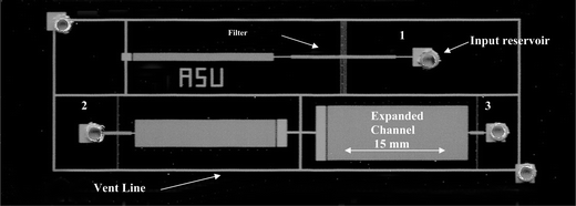 | ||
| Fig. 4 Optical micrograph of microfluidic devices fabricated in silicon and glass. Three microfilter shear rate test devices are integrated into a single test cell. (1) 15 mm long main channel, (2) 4 mm main channel, (3) 2 mm main channel. Average shear rate is controlled by adjusting the length of the filtration channel and the ratio of narrow/expanded channel area. | ||
| Device's relative level of shear rate | Main channel length/mm | Number of individual channels in expanded area | Filter length/mm | Number of filter pores |
|---|---|---|---|---|
| High | 2 | 100 | 1.4 | 12 |
| Medium | 4 | 50 | 2.8 | 24 |
| Low | 15 | 14 | 11.3 | 94 |
3.2 Device fabrication
Blood flow channels and microfilter structures were fabricated in silicon wafers (100 mm diameter, N-type <100>, Wacker Inc., Portland, OR) using the clean room facilities of the Center for Solid State Electronics Research at Arizona State University. Flow channels and the filter structures were fabricated separately on a two masking layer process using standard photolithographic techniques i.e., spin coating with OCG 825 27CS Photoresist (Arch Chemical, Norwalk, CN), exposure with a Canon PLA-501F contact aligner (Lake Success, NY), and batch development with OCG 945 developer (Arch Chemical). After photolithography, the channel and microfilter geometries were plasma-etched in silicon with SF6 using a Plasma Lab Micro RIE 80 etcher (Oxford Instruments, Concord, MA). After etching and removal of the resist, a ∼2100 Å layer of thermal oxide was grown on the silicon surface at 1050 °C in steam. Device channels were sealed by anodically bonding a 100 mm borofloat glass wafer (Technical Glass Products, Painesville Twp., OH) to the patterned silicon wafer using a laboratory-made anodic bonder operated at 500 °C and 2000 V. Prior to bonding, entrance areas into the device were fashioned by drilling access holes in the glass cover plate using diamond tipped drill bits (Lasco Diamond Products, Chatsworth, CA).3.3 Microfiltration experimental methods
Microfilter devices were tested at room temperature with citrated bovine blood (Colorado Serum, Denver, CO) at the hematocrit level provided at collection, 40%, and at a ∼50% reduced hematocrit of 19%. The latter was achieved by diluting whole blood with plasma isolated from the original sample by centrifugation at 1200g. Approximately 5 µL of blood was applied to the input reservoir of each test device using a pipette. The microdevice operation was digitally recorded with a Leica MZFL III stereoscope (Chantilly, VA), Optronics 750 video camera (Goleta, CA), and a JVC SRVS20U digital videocassette recorder (Cypress, CA). Digital video analysis using Image-Pro Plus software (Media Cybernetics, Silver Spring, MD) of the digitally recorded blood flow in the expanded channel was utilized to calculate the volumetric flow rate of blood and to determine device operation time. Specifically, a digital frame-by-frame analysis of the video was applied to measure the blood filled area of the expanded channel over time, and the fluid flow rate was computed from the measured area and the device dimensions. Similarly, after filtration ceased, digital video images of the plasma outlet channel were recorded and analyzed to determine the area of the outlet channel filled with plasma, and the volume of plasma was calculated using this area and the known device channel depth. Average filter flux of plasma was calculated using the total filter area, plasma volume, and device operation time. The average velocity of blood flow in the filtration channel was computed over time from the observed blood flow rate in the expanded channel. Wall shear rate in the filtration channel was calculated based on the average blood velocity using eqn. (6). | (6) |
Then a time-averaged wall shear rate in the filtration channel was calculated for each device. Using this data, the relationship between average wall shear rate and filter flux was evaluated for all device tests.
4 Results and discussion
A primary objective in this investigation was to study the feasibility of passive, capillarity-driven microfluidic devices for the separation of nanoliter volumes of plasma from whole blood, and to characterize the key engineering variables controlling filter flux in this system. Filtration was accomplished with transverse flow microfilters utilizing a narrow filtration channel connected in series with a larger expanded channel. This configuration maintained capillary-driven flow for an extended period of time, thereby increasing the total volume of isolated plasma. Three different microfilter designs were utilized to modulate the average wall shear rate of blood in the filtration channel, and the relationship between shear rate and filter flux was investigated. Additionally, the effect of hematocrit on filter flux was studied at two levels—19 and 40%.The microfilter devices were fabricated in 100 mm glass and silicon wafers using photolithography and reactive ion etching that provided excellent microchannel uniformity and reproducibility. Sub-micron microfilter critical dimensions were readily achieved, and device-to-device line-width and channel height uniformity was less than ±5%.
Eighteen microfilter devices were tested using citrated bovine blood. The three different microfilter designs successfully modulated the average wall shear rate of blood in the filtration channel over an observed range between 400 and 4300 s−1. Plasma volumes between 14 to 45 nl were isolated, and average plasma flux levels between 35 and 175 µm s−1 were measured (Fig. 5). Microscopy revealed that all tests produced clear-colored plasma indicating the absence of significant levels of hemoglobin and red blood cell lysis. Additionally, cells and cellular debris were not observed in the filtrate.
 | ||
| Fig. 5 Plasma flux as a function of average wall shear rate for two levels of blood hematocrit, 19 and 40% (H%). Wall shear rate was manipulated by adjusting the main filtration channel length (L). Trend line is a power law fit to data, eqn. (7), with a correlation coefficient of R2 = 0.964. Error bars indicate standard error of the mean. Three devices were tested at each point. | ||
The narrow/expanded channel design strategy produced operation times via capillary action of 30 to 110 s. Examples of the observed average velocity in the filtration channel for three different device designs tested with 19% hematocrit blood are shown in Fig. 6. As expected, the narrow/expanded channel design layout extended operating duration up to 20 times longer than predicted durations for single channel devices of equivalent lengths, and blood velocities exhibited some steady-state characteristics over time—see Fig. 6. However, in many tests the blood exhibited complex flow instabilities including oscillations in velocity and incomplete filling of the expanded channel (data not shown). These instabilities were more prevalent in devices tested with the higher hematocrit blood (40%). An accumulation of red blood cells at the leading edge of the meniscus was identified as the cause of these instabilities. This accumulation of cells at the leading edge is due to the unique flow behavior of red blood cells in small channels. It is well known that the apparent viscosity of blood decreases significantly when flowing in capillaries with diameters less than 300 μm (the Fahraeus–Lindquist effect).34 This reduction in apparent viscosity is caused by an accumulation of blood cells towards the center of the flow stream. In a capillarity driven system with a laminar flow field, the center, blood-cell-rich portion of the flowstream feeds the advancing meniscus resulting in high hematocrit blood at the leading edge. This accumulation of cells induces a high-viscosity gradient at the leading edge, which produces premature slowing of the device and complex flow behaviors such as oscillations and non-uniform filling of the flow channels. This unstable behavior can limit performance of the devices by preventing complete fill of the expanded channel, i.e. reduced filtration times; however, flow stability may be improved in device designs that maintain a higher level of velocity/shear rate in the expanded channel.
 | ||
| Fig. 6 Examples of average blood velocity in the filtration channel versus time for devices with different filtration channel lengths (L). Modification of the filtration channel length successfully produced varying levels of velocity and wall shear rate. The narrow/expanded channel design exhibited some pseudo steady-state characteristics, however, instabilities are present due to the accumulation of red cells at the advancing meniscus (see text). Data shown for 19% hematocrit bovine blood. | ||
Hemolysis was of particular concern in this study as the apparent capillary pressures generated in the filter pores upon initial wetting are very high, ∼200 kPa (30 psi). Significant hemolysis in these microfilter devices is clearly observed as a red coloration of the isolated plasma due to the presence of hemoglobin. In a separate hemolysis experiment (data not reported), the effect of pore dimensions on hemolysis was studied using digital imaging software to measure the degree of red coloration observed in micrographs of isolated plasma. In this prior study, hemolysis could not be detected, within the limits of this colorimetric technique, for pore height dimensions less than ∼0.5 μm. The validity of this pore design target for hemolysis avoidance was supported by the results of this study, as plasma extracted by the microfilter devices appeared clear and did not exhibit any visually detectable levels of hemoglobin.
The independent filtration variables evaluated in this microfilter study were blood wall shear rate, filter length, and hematocrit, because, these are the primary modulators of plasma filter flux in macroscale membrane plasmapheresis. The effects of shear rate, hematocrit, and filter length on plasma flux were evaluated over the experimental range. Wall shear rate was well correlated to plasma flux, but hematocrit and filter length were not significant. Consistent with membrane plasmapheresis, microfilter plasma flux is modulated by blood wall shear rate in the filtration channel (Fig. 5) and conforms to a power law relationship with an exponent of 0.68 (eqn. (7) in Fig. 5). Microfilter performance was compared to macroscale plasmapheresis based on predictions made using the microfilter model (eqn. (7)) and the concentration polarization model developed by Zydney and Colton, eqn. (2), as shown in Fig. 7. In this comparison, the microfilter experimental flux levels are approximately 300% higher than those of macroscale plasmapheresis.
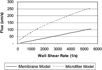 | ||
| Fig. 7 Plasma flux vs. wall shear rate for flux predictions using the microporous membrane model of Zydney and Colton (eqn. (2)) and the experimentally derived microfilter model (eqn. (7)). In this analysis, microfilter flux is approximately 3× higher than the microporous membrane filtration. Analysis is based upon assumptions of 39% hematocrit and 2.8 mm filtration length. | ||
While the relationship between microfilter flux and wall shear rate is consistent with previously discussed macroscale separations, the insensitivity of microfilter flux to hematocrit was unexpected. However, there are significant operational and physical differences between microfilter and membrane plasmapheresis. Membrane plasmapheresis is commonly performed under steady-state conditions using bundled hollow fiber membranes with filtration lengths of ∼150 mm, internal diameters of 200–400 μm, and non-uniform pores with nominal diameters ranging from 0.2 to 0.8 μm, while the experimental microfilter devices have filtration lengths of 1.4 to 11.3 mm, rectangular filtration channels 100 μm wide by 10 μm deep, and rectangular filter pores with 0.5 μm heights and 200 μm widths. Additionally, testing of the devices was performed using bovine blood treated with an anticoagulant. The performance of the devices utilizing untreated whole human blood may differ due to coagulation or variations in blood chemistry from sample to sample. Continued development of this technique will ultimately require the assessment of these factors utilizing human samples. Although unconfirmed at this date, the mechanisms controlling blood filtration at microfilter design length-scales may differ from macroscale plasmapheresis. As this is likely attributable to the significant differences in physical dimensions of the filtration components (i.e., filter pore geometry) and operating conditions, there may exist more optimal separation conditions, yet to be appreciated, and designs having broad utility in separation science.
5 Conclusions
We have demonstrated the design and operation of passive microfilter devices applicable to the separation of plasma from whole blood in miniaturized clinical diagnostic devices. These transverse flow microfilter devices operate entirely upon capillary action and may be used to effectively isolate nanoliter volumes of plasma from a single drop of blood. The micromachined format of this design is better suited to the fabrication requirements of highly integrated microfluidic designs than the prevailing microscale blood separation technologies utilizing filter paper or microporous membranes. The passive operation of the device eliminates the need for microfluidic pumps, and the duration of capillary operation is significantly extended through the use of an innovative microfluidic layout employing a narrow filtration channel connected in series with a larger expanded flow channel. Although substantial instabilities in capillarity-driven microfluidic blood flow were identified and attributed to an accumulation of blood cells at the leading edge of the flow, the onset of significant instability can be avoided by utilizing designs that maintain a minimum level of wall shear rate in the blood flow channels. Finally, microfilter models relating average wall shear rate of blood to plasma filter flux were established utilizing a power law model, which is consistent with results for macroscale membrane plasmapheresis. However unlike macroscale operations, microfilter plasma flux was insensitive to variation in hematocrit from ∼20 to 40%. On the basis of the experimentally determined microfilter flux model and well-established plasmapheresis models, the efficiency of these microfilter designs is about 3 times higher than macroscale operations.Acknowledgements
This research was funded, in part, by the ASASU Graduate Research Support Program, the NSF Research Training Group in Optical Biomolecular Devices (DBI-9602258), and the ASU Multidisciplinary Initiative on Engineering Novel Biomaterials, Biointerfaces, and Small-Scale Biohybrid Devices. We gratefully acknowledge the use of the facilities and equipment of the Center for Solid State Electronics Research (CSSER) and the Harrington Department of Bioengineering at Arizona State University. Special thanks to Prof. John Nagy, Dr Jeff LaBelle, and Prof. Mark Hayes for their assistance.References
- P. Connolly, Biosens. Bioelectron., 1995, 10, 1–6 CrossRef.
- D. Figeys and D. Pinto, Anal. Chem., 2000, 72, 330A–335A CAS.
- L. J. Kricka, Clin. Chim. Acta, 2001, 307, 219–223 CrossRef CAS.
- J. Tudos, G. A. J. Besselink and R. B. M. Schasfoort, Lab Chip, 2001, 1, 83–95 RSC.
- T. H. Schulte, R. L. Bardell and B. H. Weigl, Clin. Chim. Acta, 2002, 321, 1–10 CrossRef CAS.
- D. Erickson and D. Li, Anal. Chim. Acta, 2004, 507, 11–26 CrossRef CAS.
- P. H. Sonksen, S. L. Judd and C. Lowy, Lancet, 1978, April 8, 729–732 CrossRef.
- S. Walford, E. A. M. Gale, S. P. Allison and R. B. Tattersall, Lancet, 1978, April 8, 732–735 CrossRef.
- D. D. Cunningham, Anal. Chim. Acta, 2001, 429, 1–18 CrossRef CAS.
- J. Lichtenberg, N. F. de Rooij and E. Verpoorte, Talanta, 2002, 56, 233–266 CrossRef CAS.
- J. P. Brody, T. D. Osborn, F. K. Forster and P. Yager, Sens. Actuators A, 1996, 54, 704–708 CrossRef.
- P. Wilding, L. J. Kricka, J. Cheng, G. Hvichia, M. A. Shoffner and P. Fortina, Anal. Biochem., 1998, 257, 95–100 CrossRef CAS.
- D. C. Duffy, H. L. Gillis, J. Lin, N. F. Sheppard and G. J. Kellogg, Anal. Chem., 1999, 71, 4669–4678 CrossRef CAS.
- J. Moorthy and D. J. Beebe, Lab Chip, 2003, 3, 62–66 RSC.
- L. Zydney and C. K. Colton, Trans. Am. Soc. Artif. Intern. Organs, 1982, 28, 408–412 Search PubMed.
- P. S. Malchesky, T. Horiuchi, J. J. Lewandowski and Y. Nose, J. Membr. Sci., 1989, 44, 55–88 CrossRef CAS.
- Membrane science and technology; industrial, biological, and waste treatment processes, ed. J. E. Flinn, Plenum Press, New York, 1970 Search PubMed.
- A. A. Garcia, M. R. Bonen, J. Ramirez-Vick, M. Sadaka and A. Vuppu, Bioseparation Process Science, Blackwell Science, Inc., Malden, Massachusetts, 1999 Search PubMed.
- R. J. Forstrom, G. O. Voss and P. L. Blackshear, J. Fluids Eng., 1974, 96, 168–172.
- R. J. Forstrom, K. Bartelt, J. P. L. Blackshear and T. Wood, Trans. Am. Soc. Artif. Intern. Organs, 1975, 21, 602–607 Search PubMed.
- B. A. Solomon, F. Castino, M. J. Lysaght, C. K. Colton and L. I. Friedman, Trans. Am. Soc. Artif. Intern. Organs, 1978, 24, 21–26 Search PubMed.
- T. Martin, M. Y. Jaffrin and A. Faure, Trans. Am. Soc. Artif. Intern. Organs, 1983, 29, 735–738 Search PubMed.
- L. I. Friedman, R. A. Hardwick, J. R. Daniels, R. R. Stromberg and A. A. Ciarkowski, Artif. Organs, 1983, 7, 435–442 CrossRef CAS.
- L. Zydney and C. K. Colton, Chem. Eng. Commun., 1984, 30, 191–207 Search PubMed.
- L. H. Ding, M. Y. Jaffrin and B. B. Gupta, Trans. Am. Soc. Artif. Intern. Organs, 1986, 32, 330–333 Search PubMed.
- L. Zydney and C. K. Colton, in Artificial Organs: Proceedings of the International Symposium on Artificial Organs, Biomedical Engineering and Transplantaion in Honor of the 75th Birthday of Willem J. Kolff, ed. J. D. Andrade, J. J. Brophy, D. E. Detner and S. W. Kim, VCH Publishers, New York, 1987, pp. 343–358 Search PubMed.
- R. R. Stromberg, L. I. Friedman, D. R. Boggs and M. J. Lysaght, J. Membr. Sci., 1989, 44, 131–143 CrossRef CAS.
- J. L. Philip, M. Y. Jaffrin and L. H. Ding, Int. J. Artif. Organs, 1993, 16, 100–107 Search PubMed.
- M. J. Dunleavy, E. F. Leonard and C. S. Vassilieff, Trans. Am. Soc. Artif. Intern. Organs, 1984, 30, 657–662 Search PubMed.
- E. W. Washburn, Phys. Rev., 1921, 17, 273–283 CrossRef.
- S. E. Charm and G. S. Kurland, Blood Flow and Microcirculation, John Wiley and Sons, New York, 1974 Search PubMed.
- S. Charm and G. Kurland, Nature, 1965, 206, 617–618 CAS.
- F. J. Walburn and D. J. Schneck, Biorheology, 1976, 13, 201–210 CAS.
- R. Fahraeus and T. Lindquist, Am. J. Physiol., 1931, 96, 562–568 CAS.
Footnote |
| † Currently at Intel Corporation, Chandler, Arizona, USA. E-mail: Timothy.A.Crowley@Intel.Com. |
| This journal is © The Royal Society of Chemistry 2005 |