Continuous hydrogenation reactions in a tube reactor packed with Pd/C
Nungruethai
Yoswathananont
,
Kohei
Nitta
,
Yumi
Nishiuchi
and
Masaaki
Sato
*
Department of Chemistry, Faculty of Arts and Sciences, Osaka Prefecture University, Gakuencho 1-1, Sakai, Osaka, 599-8531, Japan. E-mail: masasato@ms.cias.osakafu-u.ac.jp; Fax: (+81) 72 254 9931; Tel: (+81) 72 254 9708
First published on 19th November 2004
Abstract
Continuous flow of the substrate solution and hydrogen gas through a tube reactor packed with Pd/C catalyst brings about a highly reactive and efficient hydrogenation system, which converts 4-cyanobenzaldehyde to the benzyl alcohol derivatives at 25 °C, and at 90 °C, the cyano group becomes reduced to give the corresponding amine and toluene derivatives within 2 min.
We wish to report an efficient hydrogenation reaction in a continuous microflow system by the use of a novel gas–liquid–solid tube reactor. It is well known that hydrogenation reactions play important roles in the chemical and pharmaceutical industries.1 In a conventional hydrogenation reaction with a batch reactor, catalyst such as palladium on carbon (Pd/C) is suspended in a solution, where substrate molecules are dissolved and hydrogen gas is bubbled through.2 This heterogeneous hydrogenation has been utilized in many organic syntheses because of its simplicity since no other than hydrogen gas is needed for the reducing agent. A disadvantage of this gas–liquid–solid reaction, however, is probably slow mass transfers between different phases. To increase the reaction rate, an autoclave has often been used in the research laboratory and the hydrogenation reactions are carried out at elevated pressures. In industry, however, the reactions at high pressures using a batch reactor should be preferably avoided for safety and economical reasons.
In recent years, flow reactors with channel space in the micrometer range, which are called microreactors,3 were reported to have advantages over exothermic reactions such as direct fluorination of organic compounds with elemental fluorine.4 Using the microreactor, the hazardous gas–liquid reaction was found to be conducted in high yield with safety.
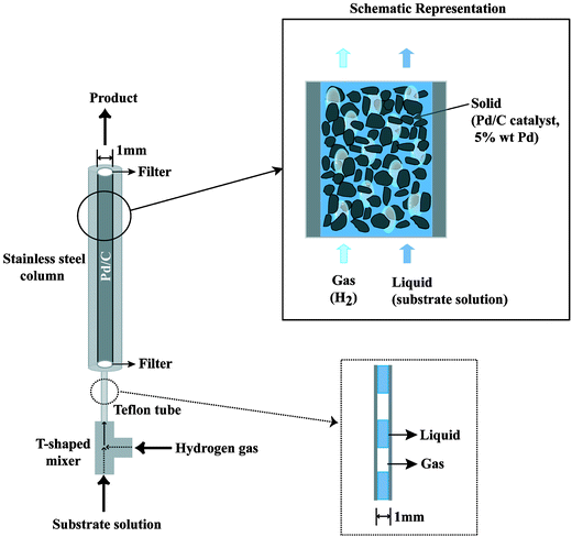
Here, we show efficient hydrogenation reactions with the use of a gas–liquid–solid microflow system under elevated pressure (Fig. 1). Both substrate solution and hydrogen gas are introduced continuously into one end of a fine column packed with Pd/C5 (5 wt% Pd). From the other end, the hydrogenated product solution emerges continuously. The residence time in the column was only 2 min. The column consists of a stainless steel tube (6.3 mm outer diameter, 1.0 mm inner diameter, 25 cm length) with two filters at both ends so as to hold the Pd/C within the column. The substrate solution was mixed with the hydrogen gas in the T-shaped mixer. A transparent Teflon tube was set between the T-shaped mixer and the tube column to observe the gas–liquid flow. A plug flow, alternate gas and liquid layers, was formed in the Teflon tube region. Maximum efficient hydrogenation took place when the plug flow was controlled to have almost the same volume of gas and liquid layers at the transparent Teflon tube. To maintain this condition, at the inlet of the column, the flow of the substrate solution was controlled to 0.038 ml min−1 by an HPLC pump and the flow of the hydrogen gas was adjusted to the same 0.038 ml min−1 by regulating the hydrogen pressure at around 2.5 MPa. This hydrogen gas flow rate corresponds to 0.95 ml min−1 at 1.0 atm, 0.1 MPa. At the outlet of the column, the product solution and the excess amount of the hydrogen gas came out to the atmospheric pressure. Therefore, the pressure drop between the inlet and the outlet of the column was 2.4 MPa, indicating that the gas–liquid flows vary inside the reactor. The hydrogen conversion within the flow reactor corresponded to the product formation, since the hydrogen dissolved in the solution was only a small amount compared with the product.6
 | ||
| Fig. 1 Schematic drawing of the gas–liquid–solid flow reactor. | ||
The substrate solution and the hydrogen gas are introduced to the tube column packed with Pd/C. They travel through very narrow channels, which are formed between and within the Pd/C porous particles having the diameter of 20 ± 10 microns. The pressure drop dissipates some energy in the liquid and gas flows inside the channels. Consequently, the stagnant layer of the carbon support catalyst particles will be very thin giving rise to enhanced mass transfers (gas–liquid and liquid–solid) relative to conventional batch reaction systems, although there is no way to quantify the hydrodynamics in the catalyst bed where liquid and gas flow through is completely unknown. In the case of homogeneous catalysts, the hydrogenation reaction itself will be fast,7 but it usually needs additional procedures to separate the product from the catalyst. Consequently, our flow system running through narrow channels formed in the Pd/C packed column, where mass transfer limitations are reduced and a separation procedure is unnecessary, is thought to give an efficient hydrogenation reaction.
Attempts to immobilize Pd catalyst on the channel wall and to carry out hydrogenation reactions in gas8 or gas–liquid9 phases have been reported in some flow systems under atmospheric or moderate pressures. To achieve high efficiencies, it was shown that micro-sized channels were essential for the flow reaction since the substrates should diffuse to the wall. These fine reactors needed expensive, complex, and multi-step fabrication, but the catalysts were not easily reactivated or renewed.
Our flow reactor, on the contrary, had a simple structure, which made the packing and renewing the Pd/C quite easy. In addition, the hydrogenation reactions could be carried out at high pressure conditions simply by increasing the flow rates of the liquid and the hydrogen gas, as there was a pressure drop in the Pd/C packed column. These flow conditions under elevated pressure were thought to facilitate the hydrogenation reaction by improving and circumventing diffusion steps.
The packing of the Pd/C into the stainless steel column with a filter at the bottom was performed by filling the Pd/C in methanol, a slurry solution, from the top at a flow rate of 0.18 ml min−1. The diameter of 1.0 mm was chosen so as to obtain both a reasonable amount and good selectivity of hydrogenated product, since a column with larger diameter tended to decrease and to lack reproducibility in the product yield. In addition, this small diameter may minimise danger in the hydrogenation reaction at high pressure.
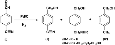
To evaluate the efficiency of our flow reactor, we chose the hydrogenation reaction of 4-cyanobenzaldehyde (I) in methanol as a model reaction. As the substrate had two functional groups, aldehyde and cyanide, and the former was more easily hydrogenated, the isolated products were 4-cyanobenzyl alcohol (II), 4-hydroxymethyl-benzylamine (III-1), bis(4-hydroxymethyl-benzyl)amine (III-2) and 4-methylbenzyl alcohol (IV). The secondary amine, III-2, seemed to be formed by an intermolecular reaction of the III-1 with the imine intermediate.10
Using the flow system at 25 °C, the substrate I was hydrogenated to II in 72% yield, where no starting material remained at all. In the case of the batch system, 70 mg Pd/C was suspended in 23 ml substrate solution with the use of a stainless steel autoclave of 50 ml capacity. The catalyst weight and the solution volume were the same as those used in the flow system. After admitting the hydrogen gas into the autoclave up to 2.5 MPa, the hydrogenation reaction was carried out with vigorous stirring for 2 min, which was equal to the residence time for the flow system. Then, the Pd/C catalyst was filtered off and the solvent was evaporated to isolate the product. Using this batch system at 25 °C, II was obtained as a sole product in a 51% yield. The remaining 49% was the starting material recovered.
At 50 °C, the hydrogen conversion rate of the flow system was faster than that of the batch system, as seen in the product yield shown in Table 1, suggesting that the flow system gave more efficient hydrogenation reaction than the batch system. In the flow system under elevated pressure, it was easy to conduct reactions at temperatures above the boiling point of the methanol solvent. At 90 °C, the cyanide group of the substrate was hydrogenated completely to give amino (III-1: 71% and III-2: 16%) or toluene derivatives (IV: 13%).11 The production of the secondary amine, III-2, could be avoided completely in the flow system by decreasing the substrate concentration from 0.167 mol L−1 to 0.033 mol L−1, where the intermolecular reaction to form the secondary amine was retarded.
In conclusion, improved hydrogen conversion and an efficient hydrogenation reaction were obtained by the use of the microflow reactor system, in which continuous flow of the substrate solution and that of hydrogen gas were led through the Pd/C packed column. Considering the high potential and wide applicability, we believe that this flow reactor system could be utilized for many organic reactions with heterogeneous catalysts.
The authors wish to thank the Research Association of Micro Chemical Process Technology (MCPT), Japan and the New Energy and Industrial Technology Development Organization (NEDO) for financial support.
Notes and references
- G. W. Kabalka and R. S. Verma, in Comprehensive Organic Synthesis, Eds. B. M. Trost and I. Fleming, Pergamon Press, Oxford, 1991, vol. 8, p. 363 Search PubMed; P. L. Mills and R. V. Chaudhari, Catal. Today, 1997, 37, 367 Search PubMed.
- H. J. R. Löwenthal and E. Zass, A Guide for the Perplexed Organic Experimentalist, John Wiley, Salzburg, 1990 Search PubMed; H. U. Blaser, H. Steiner and M. Studer, in Transition Metals for Organic Synthesis, M. Beller and C. Bolm, Eds., Wiley-VCH, Weinheim, 1998, vol. 2, p. 87 Search PubMed.
- W. Ehrfeld, V. Hessel and H. Löwe, Microreactors: New Technology for Modern Chemistry, Wiley-VCH, Weinheim, 2000 Search PubMed; W. Ehrfeld, V. Hessel and H. Lehr, Microsyst. Technol. Chem. Life Sci., 1998, 233 Search PubMed; K. F. Jensen, Chem. Eng. Sci., 2001, 56, 293 Search PubMed; P. D. I. Fletcher, S. J. Haswell, E. Pombo-Villar, B. H. Warrington, P. Watts, S. Y. F. Wong and X. Zhang, Tetrahedron, 2002, 58, 4735 CrossRef CAS.
- R. D. Chambers and R. C. H. Spink, Chem. Commun., 1999, 883 RSC; K. Jähnisch, M. Baerns, V. Hessel, W. Ehrfeld, V. Haverkamp, H. Löwe, C. Wille and A. Guber, J. Fluorine Chem., 2000, 105, 117 CrossRef CAS.
- The Pd/C catalyst was purchased from N.E.CHEMCAT Co. (AER type).
- The molar ratio of the dissolved hydrogen in the solution (at atmospheric pressure) to the product was approximately 1 ∶ 50.
- C. de Bellefon, N. Tanchoux, S. Caravieilhes, P. Grenouillet and V. Hessel, Angew. Chem., Int. Ed., 2000, 39, 3442 CrossRef CAS; C. de Bellefon, R. Abdallah, T. Lamouille, S. Caravieilhes and P. Grenouillet, Chimia, 2002, 56, 621 CAS.
- G. Wieβmeier and D. Hönicke, Ind. Eng. Chem. Res., 1996, 35, 4412 CrossRef; G. Wieβmeier and D. Hönicke, J. Micromech. Microeng., 1996, 6, 285 CrossRef.
- M. W. Losey, R. J. Jackman, S. L. Firebaugh, M. A. Schmidt and K. F. Jensen, J. Microelectromech. Syst., 2002, 11, 709 CrossRef CAS; J. Kobayashi, Y. Mori, K. Okamoto, R. Akiyama, M. Ueno, T. Kitamori and S. Kobayashi, Science, 2004, 304, 1305 CrossRef CAS.
- For reviews on the contamination of secondary amine in the catalytic hydrogenation of nitriles, see: P. Rylander, in Catalytic Hydrogenation in Organic Syntheses, Academic Press, New York, 1979, Ch 8 Search PubMed; M. Freifelder, in Catalytic Hydrogenation in Organic Synthesis. Procedure and Commentary, Wiley-Interscience, New York, 1978, Ch 6 Search PubMed; H. Greenfield, Ind. Eng. Chem., Prod. Res. Dev., 1976, 15, 156 Search PubMed.
- Toluene derivative can be produced by the hydrogenolysis of benzylamine in the hydrogenation reaction of benzonitrile using palladium-loaded pyridyl catalyst at 100 °C and 2.9 MPa; M. B. Dines, L. Beach, P. J. DiGiacomo, M. Viejo, K. P. Callahan and C. Mesa, US Patent 4 384 981, 1983 Search PubMed.
| This journal is © The Royal Society of Chemistry 2005 |

