Magnetically-driven biomimetic micro pumping using vortices†
Javier
Atencia
and
David J.
Beebe
*
Biomedical Engineering Department, University of Wisconsin-Madison, Madison, WI 53706, USA. E-mail: djbeebe@wisc.edu; Fax: +1 (608) 2659239; Tel: +1 (608) 2622260
First published on 11th November 2004
Abstract
Planar micropumps utilizing vortices shed by an oscillating ferromagnetic bar are presented. The movement of the bar is induced by magnetic coupling with an external spinning magnet. Thus, energy transfer is achieved without physical contact or need of any on-chip power source. To create vortices inside the chip, the Reynolds number is locally increased with the oscillation of the bar. The utilization of the vortices as a tool for efficient transfer of energy is inspired by the behaviour of swimming animals and flying insects in nature. The pumps operate in two different scales (milli-scale and micro-scale) in order to take advantage of both. Experiments are presented characterizing the pumps and their flow patterns. The range of operation of the pumps is from 3 µl min−1 to 600 µl min−1, though smaller flow rates are also possible.
Introduction
Animals in nature take advantage of vortices in order to propel themselves with a minimum amount of energy. For instance, insects flap their wings and create turbulences, generating several times more lift than conventional aerodynamics predicts.1 It has been demonstrated that in some cases, swimming animals can even use the energy from vortices not generated by themselves in order to move,2 and there are experiments suggesting predators could use the information left in the vortices generated in the wake of small fish in order to track their trail minutes after they are gone.3However, vortices are strongly dependent on viscosity and inertia, and therefore, on the Reynolds number. The Reynolds number, Re, is an expression of the ratio of viscous to inertial forces. At low Reynolds numbers, inertial forces are negligible compared to viscous forces,4 which implies that it is difficult to produce vortices. This has an immediate consequence: small objects at low velocities (low Re) are not capable of generating vortices as efficiently as bigger objects at high velocities (high Re). Consequently, small animals must swim continuously in order to move using vortices, while big animals can create vortices with discrete strokes. Many such examples exist, such as the way vorticella move their cilia continuously in order to create a microvortex and attract food to them (vorticella is a stalked ciliate, 50–160 µm with ciliae 2 to 10 µm long). Or, how fish change their way of movement from continuous undulatory in larvae (4 mm long) to burst and coast in adults.5
When designing micro-scale systems, it is important to understand the dominant phenomena of the scale and to leverage those phenomena to provide competitive advantages or unique functionality over macro-scale systems.4,6,7 Examples include the use of surface tension for pumping8 or directing flow,9 and the use of diffusion to establish gradients10 or sort particles by size.11 Here, we describe a magnetically-driven biomimetic micro pump designed to take advantage of both macro- and micro-scale fluid phenomena. Specifically, larger dimensions in the x–y plane (plane of oscillation) allow inertial effects that are used to create vortices, while smaller dimensions in the z plane provide viscous drag that acts to move fluid. Both the inertial and viscous properties act together to contribute to pumping.
Theory
In the realm of intermediate Reynolds number (30 < Re < 2 × 10³), it is possible to create vortices by the interaction of fluid flowing with the surface of a submerged obstacle.12The generated drag wake is called a Kármán street and consists of two rows of counter-rotating vortices with a jet meandering between them13 as shown in Fig. 1 (A). Most kinds of fish (undulatory swimmers using body or caudal fins) create in their movement a staggered array of trailing discrete vortices of alternating sign.12 This staggered structure of vortices resembles a Kármán street, but with the vortices rotating in opposite directions, as shown in Fig. 1 (B), and it is associated with high propulsive efficiency.14 Pitching foils, heaving foils, and pitching and heaving foils also exhibit reverse Kármán street within a range of values of the dimensionless Strouhal number.15 The Strouhal number is a dimensionless parameter relating the frequency of oscillation of a foil, its amplitude, and velocity of the bulk flow. At low Strouhal number the foils typically generate a Kármán street with drag, but in the range of 0.27–0.34, a reverse Kármán street is created with an associated propulsive jet and a high efficient thrust. Fish however, can use the normal Kármán street shed by a bluff (nonstreamlined) object to move against the main flow by following the drag flow of the wake and minimizing the amount of energy they use,2 as shown in Fig. 1 (C).
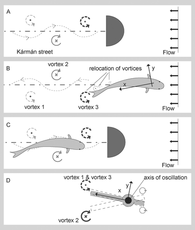 | ||
| Fig. 1 Different types of wakes. (A) Flow around a bluff object producing a Kármán street. (B) Wake generated by a fish swimming, similar to a Kármán street configuration but with opposite rotating direction. (C) A fish swimming, taking advantage of the drag jet in a Kármán street. (D) Vortices generated by a pitching bar. The x coordinate of the vortices does not change through time. | ||
Following this idea of taking advantage of vortices, the goal of this work is to generate a controllable oscillation in a pitching iron bar at controllable frequencies in order to generate vortices inside a small chamber and subsequently use them for creating liquid flow inside a chip.
Experimental
Fabrication
All devices were fabricated using µfluidic tectonics methods based on liquid-phase photopolymerization and in situ fabrication.16,17 The micropumps are composed of a ferromagnetic bar inside a layer of construction material (isobornyl acrylate, IBA). See Fig. 2. The bar is placed on top of a glass slide, and the microchannels and whole structure of the chip are created by photopolymerization of IBA inside a transparent cartridge. A post is created inside the orifice of the bar to restrict its movement to oscillations around its axis. Fig. 2 (A) shows a top view of the system with the main components.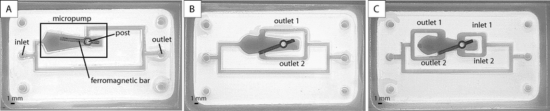 | ||
| Fig. 2 Devices designed and tested in a closed loop. Devices B and C were designed taking into account the flow patterns and vortexes generated by the oscillation of the actuator. | ||
The actuator is driven by a spinning external magnet as shown in ref. 18. A conventional magnetic stir plate (Cole Parmer, model 84000–00, Vernon Hills, IL) has been used for this purpose. A DC motor produces the torque causing the magnet to spin. The magnet acts as a magnetic coupler, transferring the mechanical energy produced by the motor to mechanical energy in the iron bar.
Flow measurements
To characterize the pumping action and obtain a curve of pressure versus frequency of oscillation of the bar, a closed-loop geometry is used. Thus, the system is governed by the pressure head of the pump and the resistance to the flow of the microchannel loop. The pressure head of the pump is calculated as a function of the frequency by first measuring the flow rates as a function of the frequency of oscillation of the bar, and then calculating the corresponding pressure with P = flow × R where R = 12 ηl/(wh3) is the resistance of the circuit to the flow, η = 0.001 Kg m−1 s−1 is the viscosity of water, l is the length of the channel in the loop, w is the width of the channel, and h is the height of the channel. A drop of blue dye is introduced to the loop with constant frequency of oscillation of the bar, and the flow rate is calculated using eqn. (1)| flow = hΔA/Δt | (1) |
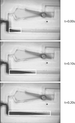 | ||
| Fig. 3 Sequence of pictures showing the movement of the dye with the flow at a constant speed of oscillation of the bar. The increment of dark area inside the white rectangles was measured to calculate the flow rate. The pictures were taken every 0.1 sec with a Sony Hyper HAD camera and an oscilloscope Olympus SZX12. | ||
Results and discussion
Characterization of the flow patterns
The device in Fig. 4 was built to explore the dynamics of the flow patterns generated by the oscillation of the bar. The bar is placed in a big chamber to allow free movement of the liquid surrounding it. The post within the orifice of the bar restricts its movement to a rotation around the axis of the post. The other two posts confine the oscillation of the bar to a 35 degree circular section. The chamber is connected to an outer loop by four microchannels.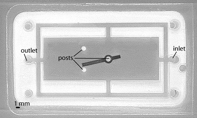 | ||
| Fig. 4 Device used for finding out the flow patterns generated by the oscillation of the bar. Three posts restrict the movement of the bar to an oscillation, while allowing the surrounding fluid to move freely. | ||
The device was filled with water. The external magnet was made to spin at a constant speed and the bar oscillated at a constant frequency. A drop of blue dye was introduced through a hole in the polycarbonate covering the top of the device and its evolution was recorded as shown in the electronic supplementary information (pump1.avi).† The video shows the creation of two counter-rotating vortices with a drag jet directed towards the bar. This experiment was repeated several times at different frequencies introducing new drops of blue dye in different locations through small predrilled holes.
Fig. 5 shows the evolution of a drop of blue dye introduced through the inlet of the device. The dye moves towards the axis of the oscillating bar. When the stream of dye reaches the end of the bar, it is mixed with the water in the two counter-rotating vortices. In Fig. 6 it is possible to discern a thin layer of concentrated dye in the boundaries between the streams of the vortices and the main flow, even though all of them are moving in the same direction towards the bar (see pump2.avi in the electronic supplementary information†). It was also observed that depending on the alignment of the axis of the magnet with the axis of oscillation of the bar, the boundaries of these streams can be moved quickly (milliseconds), changing the two-dimensional distribution of flows and pressures as shown in Fig. 6.
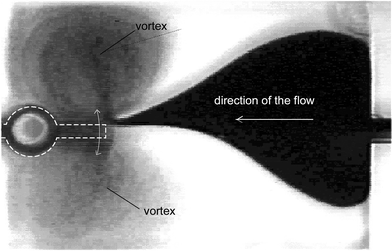 | ||
| Fig. 5 Vortices generated by the right end of the bar during oscillation. | ||
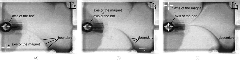 | ||
| Fig. 6 Flow patterns close to the shortest part of the oscillating bar. (A) The axis of rotation of the magnet is displaced 5 mm in the y direction; (B) The axis of rotation of the magnet is aligned with the axis of oscillation of the bar; (C) The axis of rotation of the magnet is displaced −5 mm in the y direction with respect to the axis of oscillation of the iron bar. These pictures were extracted from a video included in the electronic supplementary information (pump2).† | ||
Fig. 7 is an illustration summarizing the observations made of the flow patterns throughout all the tests. The net flow through the outer loop is from region 3 towards region 4, despite the fact that the local flow in both regions is towards the axis of the pump. However, according to our observations, the vortices in region 3 are stronger than those of region 4 and thus, the pressure in region 3 is higher than in region 4. This suggests that the net flow is driven by a simple difference in pressure between regions.
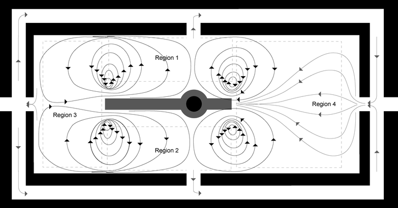 | ||
| Fig. 7 Representation of the observed flow patterns created by the oscillatory movement of the bar. In regions 1 and 2, the flow is directed away from the bar, while in regions 3 and 4, the direction of the flow is towards the bar. | ||
The oscillation of the bar generates two vortices of opposite rotational direction at each end of the bar in a similar way to a Kármán street. After reaching its maximum strength, a vortex starts fading until it disappears. In the case of fish, it leaves a characteristic trail as shown in Fig. 1 (B), whereas in the case of the oscillating bar, with every stroke, a new vortex is created in the same place where another one should be fading as shown in Fig. 1 (D). The result of several oscillations is the creation of two sustained (constant strength and position) vortices with opposite rotating directions.
In all the experiments performed, the variation of the frequency of oscillation only affected the strength of the vortices, but never their direction or position.
Design and performance of the micropumps
Three different pumps were designed and tested, taking into account the flow patterns in Fig. 7. Pump A in Fig. 2 relies on the pressure head generated by the oscillation of the bar to generate a flow. Pumps B and C in Fig. 2 however, take full advantage of the pressure field generated by the vortices and their position to create flow induced by drag. The underlying idea is to take advantage of the dragging effect of two counter-rotating vortices, as fish also do behind the wake of a Kármán street2 (shown in Fig. 1 (C)).Flow measurements with the three pumps were performed as explained in the experimental section. Fig. 8 shows the results of the tests. Pumps B and C are able to generate flow one order of magnitude higher than pump A.
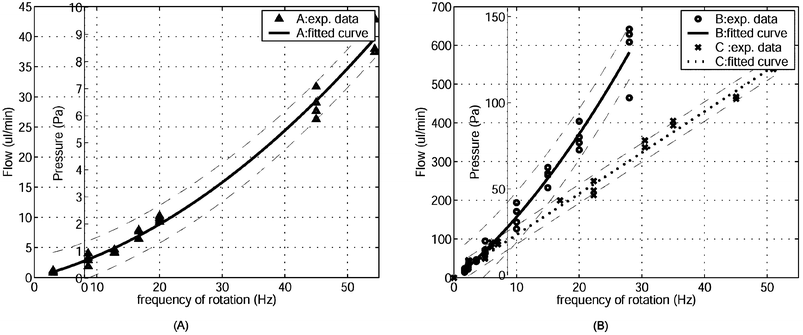 | ||
| Fig. 8 Experimental curves of pressure-head versus frequency of oscillation of the devices. (A) Experimental results and fitted curve for device A. (B) Experimental results and fitted curves for devices B and C. | ||
Since the pumps generate pressure, increasing the resistance of the channels by design would proportionally decrease the flow rates. The local flows and vortices are generated by centrifugal forces coupled with viscous drag between layers of fluid. A verification of the importance of viscosity in the operation of the pump is that the relationship between flow and frequency of oscillation is parabolic (see Fig. 8) and not linear as should be expected according to the affinity laws in macro-scale centrifugal pumps.19
According to the results of the experiments, these are volumetric pumps. They operate with low pressures and high flow rates. Therefore, they are better suited for applications with no back pressure, such as recirculation of liquids inside a chip.
Considerations on scaling
The pumps work on two different scales taking advantage of both. The momentum is transferred from the pitching bar to the liquid due to adhesion to the milliscale-surface in the x–y plane (Fig. 9) and viscous drag between layers of fluid enhanced by the micro-scale in the z direction.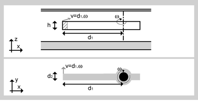 | ||
| Fig. 9 Diagram used for calculating the Reynolds number at the tip of the oscillating bar. The drawings are in a distorted scale to facilitate visualizing the whole. | ||
It is worthwhile exploring the potential use of this micropump for applications requiring a smaller surface in the x–y plane and maintaining the micro-scale in the z direction. In that case, there are two main concerns: how the forces scale down, and whether at smaller scales the production of vortices is still viable.
Regarding the first question, the dynamics involved in the operation of the pump can be modeled by eqn. (2), where Frel is the reluctance force that maintains the iron bar's alignment with the magnet, Finertia is the inertial force of the iron bar, FfrictionI is the friction force between the x–y surface of the bar (Fig. 9) and the liquid, and FfrictionII is the normal force between the x–z surface of the bar (Fig. 9) and the liquid.
| Frel = Finertia + FfrictionI + FfrictionII | (2) |
Since Frel and Finertia are volumetric, down-scaling all the measures of the x–y plane in Fig. 9 by a factor of 101 should decrease both forces by a factor of 102. FfrictionI also would decrease by a factor of 102, and FfrictionII by a factor of 101. According to all this, if FfrictionII is too high for the pump to oscillate, an increase of Frel by increasing the magnetic field should solve the problem.
Regarding the ability to generate vortices at smaller scales, the Reynolds number at the tip of the bar (Fig. 9) in the plane of the oscillation can be calculated with eqn. 3, where v is a characteristic velocity (velocity at the tip of the actuator), a is a characteristic length of the system, perpendicular to the velocity (hydraulic diameter), h is the width of the bar, d1 is the distance from the axis of rotation to the tip of the bar; f is the frequency of oscillation of the bar and υ is the kinematic viscosity of water.
| Re = aν/υ = h(d12π·f)/υ | (3) |
When the bar oscillates at the maximum frequency of 50 Hz, then Re = 314 (h = 200 × 10−6 m, d1 = 4 × 10⁻³ m, υ = 10−4 s m−2). Even when the frequency is reduced ten times to 5 Hz, the Reynolds number is approximately Re = 30, which is consistent with the production of vortices.12 From all the measurements of the surface of the x–y plane in Fig. 9, only d1 affects the Reynolds number: Re ≈ d1·f. Therefore if d1 is reduced by a factor of 10, increasing the frequency of rotation of the magnet by a factor of 10 (so that the max is 500 Hz) leaves the Reynolds number in the same range of values, and thus, allows exploitation of the inertial effects. Thus, the basic design principles apply across a range of scales relevant to microfluidics.
Conclusions
Understanding the mechanisms of energy conversion in nature will continue to be one of the most powerful sources of ideas for creating more efficient actuators. In this paper, based on the mechanisms of fluid displacement in the animal kingdom through the creation of vortices, we have designed, built, and tested a new kind of simple and robust micropump that expands the microfluidic design capabilities in microsystems.The pumps are composed of a ferromagnetic bar capable of rotation and a chamber that restricts its movement to an oscillation. This configuration makes them especially interesting for applications with no back pressure where the chip or platform is composed of only one layer. No necessity for on-chip power or physical connectors to the ‘outside world’ also simplifies the fabrication process considerably. The highest flow rate tested was 600 µl min−1 at a frequency of rotation of the external magnet of 50 Hz. The lowest flow rate used was 3 µl min−1, limited by the lowest frequency of rotation of the motor of the magnetic stir plate. However, this flow can be further reduced with a slower motor, or by increasing the total resistance to flow of the circuit.
The micropumps operate at two different scales: macro-scale to create vortices, and micro-scale to reduce inertia of the actuator and enhance viscous drag between layers of liquid. By borrowing concepts from nature and combining them with appropriate micro-scale design, a pump was realized that leverages both macro- and micro-scale phenomena.
Acknowledgements
Special thanks to Glennys Mensing for her help through the set up and experiments. Thanks also to Professor Mike Graham for valuable discussions, and to Professor Wendy Crown for her support in the fabrication of the ferromagnetic bars. J. Atencia thanks the “Ministerio de Educacion, Deporte y Cultura” of Spain for financial support.References
- J. M. Birch and M. H. Dickinson, Nature, 2001, 412, 729–733 CrossRef CAS.
- J. C. Liao, D. N. Beal, G. V. Lauder and M. S. Triantafyllou, Science, 2003, 302, 1566–1569 CrossRef CAS.
- W. Hanke, C. Brucker and H. Bleckmann, J. Exp. Biol., 2000, 203, 1193–1200 Search PubMed.
- E. Purcell, Am. J. Phys., 1977, 45, 3–11.
- U. K. Muller, E. J. Stamhuis and J. J. Videler, J. Exp. Biol., 2000, 203, 193–206 Search PubMed.
- J. P. Brody, P. Yager, R. E. Goldstein and R. Austin, Biophys. J., 1996, 71, 3430–3441 CrossRef CAS.
- D. J. Beebe, G. A. Mensing and G. M. Walker, Annu. Rev. Biomed. Eng., 2002, 4, 261–286 Search PubMed.
- G. M. Walker and D. J. Beebe, Lab Chip, 2002, 2, 131–134 RSC.
- B. Zhao, J. Moore and D. J. Beebe, Science, 2001, 291, 1023–1026 CrossRef CAS.
- S. K. W. Dertinger, D. T. Chiu, N. L. Jeon and G. M. Whitesides, Anal. Chem., 2001, 73, 1240–1246 CrossRef CAS.
- B. H. Weigl and P. Yager, Science, 1999, 283, 346–347 CrossRef.
- M. Sfakiotakis, D. M. Lane and J. B. C. Davies, IEEE J. Oceanic Eng., 1999, 24, 237–252 CrossRef.
- U. K. Muller, Science, 2003, 302, 1511–1512 CrossRef.
- M. S. Triantafyllou, G. S. Triantafyllou and D. K. P. Yue, Annu. Rev. Fluid Mech., 2000, 32, 33 Search PubMed.
- M. Triantafyllou, A. Techet and F. Hover, IEEE J. Oceanic Eng., 2004, 29, 585–594 Search PubMed.
- C. Khoury, G. Mensing and D. J. Beebe, Lab Chip, 2002, 2, 50–55 RSC.
- D. J. Beebe, J. S. Moore, Q. Yu, R. H. Liu, M. L. Kraft, B. H. Jo and C. Devadoss, Proc. Nat. Acad. Sci. USA, 2000, 97, 13488–13493 CrossRef CAS.
- J. Atencia and D. J. Beebe, in Proceedings of the uTAS 2003, Kluwer Academic Publishers, Dordrecht, The Netherlands, 2003, vol. 2, 883–6 Search PubMed.
- A. J. Stepanoff, Centrifugal and Axial Flow Pumps: Theory, Design and Application, John Wiley & Sons, New York, USA, 1957 Search PubMed.
Footnote |
| † Electronic supplementary information (ESI) available: videoclips of micropumps in action. See http://www.rsc.org/suppdata/lc/b4/b407710e/ |
| This journal is © The Royal Society of Chemistry 2004 |