Study of monolayer dispersion of MoO3 on muscovite powder and diffusing behavior of MoO3 on muscovite wafer by SR-TXRF
Liyan
Zhao
a,
Xuekai
Wang
a,
Nianzu
Wu
*a,
Yuying
Huang
b,
Wei
He
b and
Youchang
Xie
a
aState Key Laboratory for Structural Chemistry of Unstable & Stable Species, Institute of Physical Chemistry, Peking University, Beijing 100871, P. R. China. E-mail: wunz@chem.pku.edu.cn
bInstitute of High Energy Physics, Chinese Academy of Sciences, Beijing 100039, P. R. China
First published on 15th November 2002
Abstract
The dispersion capacity of MoO3 on the surface of muscovite powder was studied by X-ray photoelectron spectroscopy (XPS) and X-ray diffraction (XRD) techniques. The results indicated that MoO3 can disperse onto the surface of a support as a sub-monolayer. The dispersion capacity was 5.88 mg MoO3 (g muscovite)−1, or 3.24 Mo atoms nm−2. The diffusing process of MoO3 on muscovite wafer was investigated by means of Synchrotron Radiation excited Total-reflection X-Ray Fluorescence spectroscopy (SR-TXRF). A stripe of MoO3 on the muscovite wafer was used as the diffusion source. After thermal treatment in air or dry N2, MoO3 diffuses onto the surface of muscovite and forms a sub-monolayer. Sublimation of MoO3 was also detected during the diffusion process. The diffusion rate in two heating atmospheres differed significantly. The diffusion rate of MoO3 on muscovite in dry N2 was greater than that in air. A possible explanation of the phenomena is that surface diffusion onto the muscovite surface plays a more important role in the process than transportation via gas phase during the diffusion of MoO3.
Introduction
Xie and Tang1 suggested that many oxides and salts can disperse spontaneously onto the surface of supports to form a monolayer or submonolayer, at a temperature well below the melting point of the dispersates. For each system, there is an utmost dispersion capacity, namely, the threshold. Monolayer dispersion is a ubiquitous phenomenon, which has been applied extensively in the preparation of heterogeneous catalysts and adsorbents. Since surface diffusion plays an important role in preparation and application of monolayer-type catalysts, it is significant to study the mechanism of the diffusion of supported metal oxides.The study of supported molybdena catalysts continues to be interesting because of their numerous applications in petroleum refining, chemical production, and pollution control industries. Traditionally, most of the research about monolayer dispersion focuses on the systems that consist of molybdenum trioxide dispersed on a support with a high specific surface area.2–11 Since the surface structure of the support is usually too complicated to be adequately elucidated, it is hard to observe the diffusing process in a real powder system clearly.
Knözinger's group has already paid attention to the study of the diffusing process and the diffusing mechanism. At first, they investigated systems similar to real powder ones, which consisted of an alumina wafer in contact with a molybdenum trioxide wafer. Since they used the oxide powder as supports, this lead to uncertainty when studying the spreading phenomena.12 In their later work, they used model systems such as alumina and titania thin films and observed the diffusion in the close vicinity of the homogeneously deposited MoO3 crystal.13,14
In our previous work, we investigated MoO3 diffusion behavior on alumina, titania and silica thin films.15–17 By vacuum evaporation, a stripe of MoO3 on the oxide thin film was used as the diffusion source. The diffusion source had much stronger contact with the support than previously reported ones.13,14 Because the supports are nano-scale flat (according to Atomic Force Microscopy (AFM)) they are less smooth than the surface of muscovite since muscovite has an atomic flat plane.
In this paper, we study monolayer dispersion of MoO3 on the surface of muscovite powder by means of XPS and XRD. At the same time, muscovite wafer was also used as the support, whose atomic flat surface enables us to study the diffusion process of MoO3 clearly. A small amount of MoO3 was vaporized in vacuum and deposited onto the slot of a mask on the muscovite wafer. Thus the stripe of MoO3 on the muscovite surface was used as the diffusion source. After thermal treatment, the signals of line scans across the diffusion source and the diffusion region were acquired by SR-TXRF.
SR-TXRF is a very surface sensitive technique for trace element analysis. Since synchrotron radiation has many merits such as very high brightness, natural collimation and polarization etc., SR-TXRF is a more sensitive analysis method than conventional XRF in elemental detection sensitivity and space resolution. In Beijing Synchrotron Radiation Facility (BSRF), the minimum detection limit obtained by SR-TXRF can be as low as ng g−1, or ppb in the micro area, much lower than that of XPS and Secondary Ion Mass Spectrometry (SIMS). Therefore, this method was used to analyze the samples with a monolayer or sub-monolayer of MoO3 on the surface.
Experimental
Preparation of the samples
Muscovite powder was used as support. The BET surface area of the support was 7.6 m2 g−1. Muscovite powder was mechanically mixed with the required amount of MoO3 in an agate mortar. After complete mixing, all the samples were calcined at 673 K for 8 h.In order to study the diffusing behavior of MoO3 on the muscovite surface, freshly cleaved muscovite wafer was prepared as the support. The wafer was cut to the size of 20 mm (X direction) × 10 mm (Y direction). Then, by using a mask with a slit 2 mm wide, MoO3 was evaporated onto the muscovite surface in vacuum (JEE-4C Vacuum Evaporator) forming a stripe which was the diffusion source. After being heated in an air atmosphere (78 vol.% nitrogen, 21 vol.% oxygen, ca. 65% relative humidity) or in a dry N2 atmosphere (99.995 vol.%, little water) at 673 K in a quartz tube furnace for different numbers of hours, the samples were prepared for further characterization.
Characterization of the samples
XRD was carried out by means of a Rigaku D/max 2000 X-ray powder diffractometer, employing Cu Kα (Ni filtered) radiation of wavelength 1.542 Å. The accelerating voltage was 50 kV and the anode current was 120 mA.XPS spectra were acquired with a VG-ESCA LAB 5 spectrometer with Mg Kα X-ray source operated at 9 kV and 18.5 mA. The pressure in the chamber was less than 1.0 × 10⁻⁷ Torr. Electron binding energies were calibrated against the C1s emission at Eb = 284.8 eV. The XPS peak intensity ratio between Mo 3d and Si 2p was taken as a measurement of the relative content of MoO3 on the surface of the muscovite.
The Synchrotron Radiation excited Total-reflection X-Ray Fluorescence (SR-TXRF) data were acquired by Beijing Synchrotron Radiation Facility. White light was used as the excitation source. After it passed through a 40 µm (X) × 80 µm (Y) slit, it contacted the sample with grazing incidence. The fluorescence spectra were recorded by the Si (Li) detector. Then the sample stage was moved perpendicular to the diffusion source (along the X direction) and in the plane parallel to the surface. Thus, a line scan was made. The origin of the scan is the center of the diffusion source determined by microscopy.
Results and discussion
Dispersion capacity of MoO3 on muscovite powder
Since XPS is a surface sensitive technique, it can be used to study the surface state of MoO3 supported on muscovite. The intensity ratio of the XPS peak IMo3d/ISi2p as a function of MoO3 content is illustrated in Fig. 1. The figure consists of two straight lines with different slopes; and at the intersection point the MoO3 content is 5.22 mg g−1 muscovite. This value is called the utmost dispersion capacity of MoO3 on muscovite. When the MoO3 content is below the value, the line slope is rather steep, which indicates that MoO3 disperses on the muscovite surface as a highly dispersed monolayer.1 With an increase in highly dispersed MoO3 loading, IMo3d/ISi2p increases quickly. However, beyond the value, the slope of the line becomes smaller, which reveals that the dispersity of MoO3 goes down. Crystalline MoO3 appears and might exist on the support surface of dispersed MoO3 or mixed with it mechanically. Although the loading is increasing, the surface area of MoO3 exposed to X-rays does not increase to the same degree. Therefore the increasing rate of IMo3d/ISi2p slows.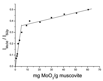 | ||
| Fig. 1 XPS peak intensity ratio IMo3d/ISi2pversus the content of MoO3. | ||
The dispersion capacity of MoO3 on muscovite is also obtained by XRD measurement. XRD quantitative phase analysis to determine the dispersion capacity of the metal oxides on the support has been discussed elsewhere.1 The intensity ratio of the XRD peak IMoO3(2θ = 12.768)/Imuscovite (2θ = 17.738) as a function of MoO3 content is illustrated in Fig. 2.
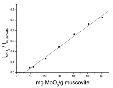 | ||
| Fig. 2 XRD peak intensity ratio IMoO3/Imuscoviteversus the content of MoO3. | ||
In Fig. 2, for lower loading, no crystalline MoO3 is detected. This indicates that the period structure of crystalline MoO3 is destroyed, i.e. Mo species are highly dispersed onto the surface of muscovite powder as mentioned above. When the loading is increasing, crystalline MoO3 begins to appear in an orthorhombic crystal form. The intensity ratio of the XRD peak IMoO3/Imuscovite above the intercept point represents the relative amount of residual crystalline MoO3 in the samples. The intercept of the straight line with the X-axis corresponds to the utmost dispersion capacity of MoO3 on the surface of the muscovite. Below the threshold the amount of residual crystalline MoO3 is zero. The intercept is 5.88 mg MoO3 g−1 muscovite, close to the value determined by the XPS technique. We determined the dispersion capacity of MoO3 to be 5.88 mg g−1 muscovite, equal to 3.24 Mo atoms nm−2, since the specific surface area of muscovite is 7.6 m2 g−1. This calculation is based on the results of XRD because the error of the intensity ratio is a bit larger for XPS analysis of low loading samples.
For 1.4 mg MoO3 g−1 muscovite sample, no diffraction peaks of MoO3 were seen in the XRD pattern. When physically mixing the system containing the same content of MoO3 and muscovite powder without the following calcination, the characteristic diffraction peaks of MoO3 in its XRD pattern could be seen. This means that the disappearance of diffraction peaks of MoO3 in low loading samples was due to the dispersion of MoO3 onto the surface of muscovite, not because of the detection limit of the X-ray diffractometer.
The diffusion of MoO3 on muscovite wafer
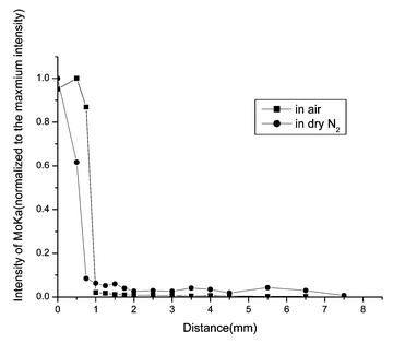
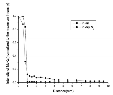
To determine the species of the diffusion source, XPS and XRD measurements were used. The binding energies of Mo 3d3/2 and Mo 3d5/2 were 235.79 and 232.60 eV respectively, which confirms that the diffusion source is MoO3 and it belongs to orthorhombic MoO3 as shown by the results of the XRD measurements. Within the detection limits of SR-TRXF, no Mo species were found outside the stripe of the diffusion source without heating.The SR-TXRF line scans for MoO3/muscovite samples are illustrated in Fig. 3–6.
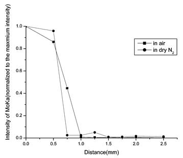 | ||
| Fig. 3 SR-TRXF line scans in the X direction for MoO3/muscovite samples heated for 4 h in two different atmospheres. | ||
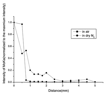 | ||
| Fig. 4 SR-TRXF line scans in the X direction for MoO3/muscovite samples heated for 12 h in two different atmospheres. | ||
 | ||
| Fig. 5 SR-TRXF line scans in the X direction for MoO3/muscovite samples heated for 18 h in two different atmospheres. | ||
 | ||
| Fig. 6 SR-TRXF line scans in the X direction for MoO3/muscovite samples heated for 24 h in two different atmospheres. | ||
The common feature of the four figures is that Mo species were detected in the diffusion region. That means, after thermal treatment, MoO3 can spontaneously diffuse onto the surface of muscovite. From all the figures, it can be clearly seen that the integral area of Mo Kα peak (about 17.444 keV) decreases dramatically outside the diffusion source. In the diffusion source, the concentration of MoO3 of samples prepared in air is higher than in dry N2. On the contrary, outside the diffusion source, the concentration of MoO3 of samples prepared in dry N2 is higher than in air. The second data point of the sample heated for 4 h in dry N2 and the third data point of the sample heated for 12 h in air are significant. Perhaps for the places where the two data points lie, the roughness of the sample is a bit greater and lead to the deviation of the total reflection. Under the two heating atmospheres, increasing the heating time, the diffusion regions become more and more distant. With the same heating time, the diffusion distance in dry N2 is longer than that in air. That means, the presence of water in the gas phase cannot enhance the spreading velocity.
From all of the above results, it can be seen that after being heated at 673 K for some time, MoO3 spontaneously disperses onto the surface of muscovite.
XPS was used to analyze the whole diffusion region, which had been prepared by cutting away the diffusion source from the heated sample. For MoO3/muscovite powder system prepared by mechanical mixing, when the content of MoO3 is up to the threshold, the intensity ratio (IMo3d/ISi2p) is 0.358. For the MoO3/muscovite surface system, although the sample is heated for 24 h in dry N2, in the diffusion region the intensity ratio (IMo3d/ISi2p) is 0.132, much less than that of the threshold.
As with MoO3 supported on Al2O3, SiO2 and TiO2 thin film systems,16,17 besides the surface diffusion, sublimation of MoO3 was also detected during thermal treatment under both atmospheres. Using SR-TXRF, Mo species were detected on the fresh muscovite surface placed beside the sample during the heating process. However, XPS cannot detect the occurrence of sublimation under both atmospheres due to the detection sensitivity. S. Günther14 found that the presence of water in the gas phase could enhance the spreading of MoO3 on a flat Al2O3 support. Yan15 also suggested that moisture could accelerate the diffusion rate of MoO3 on the surface of Al2O3. In this study the spreading rate of MoO3 on muscovite in dry N2 atmosphere is greater than that in air. This discrepancy may be related to the different surface properties of the supports or to different experimental conditions.
Although the transport mechanism for the diffusion of MoO3 on a molecular level is still not fully understood, Knözinger and Taglauer have suggested three possible explanations for the phenomenon:18 (a) unrolling carpet mechanism: Mo oxide species, diffusing on top of crystalline MoO3 particles, are trapped at the edge of the crystal before reaching the support surface; (b) surface diffusion on the support: Mo oxide species, detached from the MoO3 crystals, diffuse and nucleate on the surface of the support foil and eventually recystallize at certain spots; (c) transport via the gas phase: Mo oxide species from the MoO3 crystals sublimate and spread on the support via subsequent recondensation and finally recrystallize at certain spots.
In our study of diffusion in the MoO3/muscovite system, surface diffusion and sublimation are both observed. The unrolling carpet mechanism is ruled out, because after a long time of heating the Mo oxide species on the diffusion region are still less than a monolayer. The mechanism that diffusion of MoO3 completely depends on transport via the gas phase is also ruled out. The reason is as follows: MoO3 is known to sublime at around 700 K, which was observed in our experiment. In the presence of water, the oxyhydroxide MoO2(OH)2 can be formed,12 a compound with a higher vapor pressure than MoO3. Therefore moisture can promote the sublimation; that is to say, the sublimation in air is more obvious. If transportation via the gas phase plays a critical role in the diffusion, then the spreading rate of MoO3 on muscovite should be greater in air than in dry N2. Although in air sublimation is more obvious than in dry N2, MoO3 in the gas phase can condense onto any surrounding place. If only considering the sublimation the amount of MoO3 in the diffusion source in dry N2 is greater than in air, which means the initial concentration of spread phase is greater in dry N2 atmosphere. Therefore we propose that the surface diffusion is of a critical role on the diffusion of MoO3 on muscovite.
From the results of XPS analysis for the diffusion region and sublimation, it can be concluded that sublimation has only a little effect upon the diffusion of MoO3 on the muscovite wafer.
Conclusions
In the present report, we firstly obtained that MoO3 can be highly dispersed as a sub-monolayer on the surface of muscovite powder by conventional mechanical mixing and heating. The dispersion capacity of MoO3 on muscovite powder is 3.24 Mo atoms nm−2 determined by XPS and XRD techniques. Meanwhile we investigated the diffusion behavior of MoO3 on the flat surface of a muscovite wafer. It is proved, by SR-TXRF line scans, that MoO3 can spontaneously disperse onto the surface of the muscovite, and form a sub-monolayer. The diffusion rate of MoO3 on muscovite in dry N2 atmosphere is greater than that in air. Sublimation of MoO3 is observed during thermal treatment under two heating atmospheres. A possible explanation is that surface diffusion on the support plays a more important role compared with transportation via gas phase during the diffusion process of MoO3.Acknowledgements
This program is financially supported by National Natural Foundation of China (No. 29733080) and the Major State Basic Research Development Program (Grant No. G2000077503). We are grateful to Meijuan Zhao for cooperation during the preparing of samples.References
- Y. C. Xie and Y. Q. Tang, Adv. Catal., 1990, 37, 1 Search PubMed.
- R. Radhakrishnan, C. Reed and S. T. Oyama, J. Phys. Chem. B, 2001, 105, 8519 CrossRef CAS.
- M. Zdrazil, Catal. Today, 2001, 65, 301 CrossRef CAS.
- T. Olorunyolemi and R. A. Kydd, Catal. Lett., 2000, 65, 185 Search PubMed.
- F. Xu, Y. H. Hu, L. Dong and Y. Chen, Chin. Sci. Bull., 2000, 45, 214 Search PubMed.
- M. E. Harlin, A. O. I. Krause, B. Heinrich, C. Pharm-Huu and M. J. Ledoux, Appl. Catal. A-Gen., 1999, 185, 311 Search PubMed.
- D. Klissurski, D. Petridis, N. Abadzhieva and K. Hadjiivanov, Appl. Clay Sci., 1996, 10, 451 CrossRef CAS.
- T. Suzuki, H. I. Iwanami, T. Yoshizawa, H. Yamazaki and Y. Yoshida, Int. J. Hydrogen Energy, 1995, 20, 823 CrossRef CAS.
- R.W. Borry, Y. H. Kim, A. Huffsmith, J. A. Reimer and E. Iglesia, J. Phys. Chem. B, 1999, 103, 5787 CrossRef.
- L. Dong and Y. Chen, J. Chem. Soc. Faraday Trans., 1996, 92, 4589 RSC.
- L. J. Lakshmi and E. C. Alyea, Catal. Lett., 1999, 59, 73 Search PubMed.
- J. Leyrer, D. Mey and H. Knözinger, J. Catal., 1990, 124, 349 CrossRef CAS.
- S. Günther, M. Marsi, A. Kolmakov, M. Kiskinova, M. Noeske, E. Tagauer, G. Mestl, U. A. Schubert and H. Knözinger, J. Phys. Chem. B, 1997, 101, 10004 CrossRef.
- S. Günther, L. Gregoratti, M. Kiskinova, E. Taglauer, P. Grotz, U. A. Schubert and H. Knözinger, J. Chem. Phys., 2000, 112, 5440 CrossRef CAS.
- J. F. Yan, N. Z. Wu, H. X. Zhang, Y. C. Xie, Y. Q. Tang, Y. F. Zhu and W. Q. Yao, Acta Phys-Chim. Sin., 1999, 15, 684 Search PubMed.
- W. M. Xu, J. F. Yan, N. Z. Wu, H. X. Zhang, Y. C. Xie, Y. Q. Tang and Y. F. Zhu, Surf. Sci., 2000, 470, 121 CrossRef CAS.
- W. M. Xu, J. Q. Xu, N. Z. Wu, J. F. Yan, Y. F. Zhu, Y. Y. Huang, W. He and Y. C. Xie, Surf. Interface Anal., 2001, 32, 301 CrossRef CAS.
- H. Knözinger and E. Taglauer, in Catalysis, The Royal Society of Chemistry, Cambridge, 1993, vol. 10, p. 1 Search PubMed.
| This journal is © The Royal Society of Chemistry 2003 |