On-line gas chromatographic monitoring of catalyst processes in a microfabricated chemical reactor
Bashar R. M.
Al-Gailani
and
Tom
McCreedy
*
Department of Chemistry, University of Hull, Hull, UK HU6 7RX. E-mail: T.McCreedy@Hull.ac.uk; Fax: 44 (0)1482 466416; Tel: 44 (0)1482 466407
First published on 25th November 2002
Abstract
A microfabricated catalyst reactor, prepared from glass and polydimethylsiloxane, has been directly interfaced to a gas chromatograph permitting real time reaction monitoring allowing rapid catalyst characterisation.
Microfabricated reactors offer a unique opportunity to observe chemical reactions in a totally controlled and predictable state. Factors that lead to this include precise control of reaction time and temperature, and mass transfer processes that are predictable and repeatable. While such devices have great advantages in many synthetic processes,1 one significant problem is the difficulty in obtaining real time product characterisation and quantification. The most common method employed is to collect the products formed and analyse them off line by GC–MS or any other appropriate analytical method. This can be quite straightforward if a little restrictive for liquid phase reactions, but is far more complex in reactions where the product is a gas. The ideal solution is to adopt an on-line analysis system, which has automated sample transfer without the requirement to collect the product over an extended time period. Recently, we reported a method for directly interfacing a microfabricated reactor to a gas chromatograph using a transfer needle directly from the chip and pumping by electroosmotic flow.2 This showed the feasibility of direct interfacing, but was not suitable for gas phase reactions and the time scale for sample introduction was long (typical injection times of 60 s).
Microfabricated reactors for heterogeneous catalysis offer the advantages already discussed above, but the amount of catalyst required is minute (typically a few mg), and the potential exists to screen the activity of numerous catalysts under the same conditions by scaling out the reactor. There have been many reports of microfabricated reactors for catalysis, using packed or open tube style channels. Srinivasan et al. manufactured a silicon based microreactor for catalytic partial oxidation reactions,3 while Cui and co-workers fabricated a silicon microreactor for the dehydrogenation of cyclohexene to benzene.4 The platinum catalyst was sputtered onto the channel walls. Zeolites have been incorporated into microreactor systems both as catalysts and membrane separators.5 Microreactors for catalysis have been packed with solid particulate matter by Losey et al.6 They fabricated a 25 μm filter into the channel to retain the particulate material and the system was evaluated using the hydrogenation of cyclohexene. On-line detection will prove very important to developing microreactors for catalysis, however, some approaches have already been reported. Photoacoustic spectroscopy has been developed for low level gas detection and catalyst characterisation7 and shows considerable promise for miniature chemical systems. An alternative approach, reported by Claus et al.8 used a scanning mass spectrometer to monitor a high throughput heterogeneous reactor. Typical reactions involved the oxidation of methanol, oxidation of CO, and the dehydrogenation of isobutane. Infrared spectroscopy has been reported as a method for monitoring reactions occurring within a microreactor,9,10 however, it does require that the reactor be manufactured from IR transparent material.
We developed the first heated glass and polydimethylsiloxane reactor for heterogeneous catalysis where electroosmotic flow was used to deliver the reactant, in that case ethanol.11,12 While this work had immense benefits such as requiring no mechanical pumping and gave a very high conversion efficiencies, the two possible drawbacks were the limited number of suitable reactants that could be moved electroosmotically, and the slow rate of throughput. This latter point is certainly not a disadvantage for a synthetic catalyst reactor (i.e. one used to produce a single product with high efficiency), but for catalyst evaluation and development, the throughput rate certainly limits its value. An alternative reactant delivery system, which overcomes these limitations is to disperse the reactant in a stream of helium or nitrogen and use this to deliver the reactants to the reactor. This provides typically a vapour composition of 10% reactant, but is it highly dependent on the volatility of the reactant. It is not possible nor desirable to operate such reactors at gas pressures directly compatible with the column head pressures encountered in gas chromatography i.e. 30 psi due to constant leaks and an excessively high flow rate through the reactor. In addition, the great benefit of the system proposed in this paper is the simplicity of construction and the absence of complex mechanical devices and pressure seals.
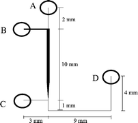
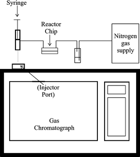
The reactor was fabricated using a previously reported methodology13 with the channel network etched into a glass base plate and the reservoirs located in a removable polydimethlysiloxane (PDMS) top plate. The glass base plate (Photonics, UK) was coated with a layer of chromium and photoresist. It was photolithographically patterned then etched in 1% hydrofluoric acid/ammonium fluoride for 10 min at 60 °C. The channel network can be seen in Fig. 1, the positions of the reservoirs are labelled A–D. The channel from reservoir C to D was 150 μm wide, from reservoir B to the wide section was 200 μm wide, and the wide section (where the catalyst was packed) was 350 μm wide. All channels were 50 μm deep. The wider channel sections were required to permit packing of the reactor. The top plate was made from PDMS (ISL, West Midlands, UK), which was prepared according to instructions, vacuum degassed, and then moulded with the reservoirs in place. These were 1.5 mm diameter, and permitted PTFE tubing to be fitted into the reservoirs after curing. A heating element, constructed from Nichrome wire (Goodfellows, UK) was incorperated into the top plate within 2 mm of the channel network. The two halves of the reactor were held together by a simple metal clamp with four corner bolts to apply pressure. The device could easily be disassembled for cleaning whenever required. The catalyst was packed into the enlarged section of the channel network via reservoirs B and C. Once the packing process was complete, the two reservoirs were sealed. Reservoir A was used to deliver the reactant stream to the catalyst channel, while the product stream exited via tubing secured in reservoir D. The product stream was allowed to flow to waste via a modified 1 ml plastic syringe. The plunger was positioned so that the internal volume of the syringe was 250 μl. A hole was then drilled just ahead of the plunger. The product stream entered via the hole in the side wall of the syringe, thus constantly flushing the syringe. By inserting the syringe into the gas chromatograph and depressing the plunger, it is possible to directly intoduce 250 μl of product stream into the gas chromatograph. This provides a very simple and reliable method to sample the product stream and introduce it into the gas chromatograph without having to stop the reaction or collect product over a long period of time (thus producing a time resolved result rather than a time averaged result). A schematic of the experimental setup can be seen in Fig. 2. The gas chromatograph (Autosystem, Perkin Elmer, Beckonsfield, UK) was fitted with a Porapak Q column operated at 190 °C and the injector and flame ionisation detector were operated at 250 and 200 °C, respectively.The carrier gas was nitrogen at 30 psi. The reactor chip was heated using a 0–15 V power supply connected to the Nichrome wire. We estimate (from volume flowrates) that the residence time of any reactant molecule in the catalyst reactor was 0.1 s.
 | ||
| Fig. 1 A schematic layout of the channel configuration. | ||
 | ||
| Fig. 2 Schematic diagram of the apparatus. | ||
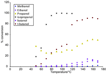
We chose to use the same catalyst as in previous reactions since its charateristics were well known, a reliable synthetic route existed, and it provided comparative data to previous reactions studied. In addition, since the aim of the work was to develop and demonstrate a method for catalyst evaluation, it was indeed beneficial to select a well studied catalyst. The catalyst was prepared using a method reported by Yori and Parera,14 giving a surface area of 120 m2 g−1 and a particle size of 10 μm. Typical loading in the reactor was 10 mg of catalyst. The dehydration of alcohols using a sulfated zirconia catalyst was selected as the reaction, and alcohols from methanol through to butanol were studied. The percentage conversion of each alcohol to the corresponding alkene could be quickly and simply determined over a temperature range from room temperature to 180 °C in about 1 to 2 h, depending on the temperatue step. The percentage conversion was calculated from the peak areas of the starting material (alcohol) and the product (alkene). The byproducts of reaction were below limits of detection, indeed, no apparent by products were seen. In Fig. 3, a graph of dehydration efficiency versus temperature is shown.
 | ||
| Fig. 3 Graph of alcohol conversion efficiency versus temperature. | ||
The results from the reaction are not novel, indeed the dehydration of alcohols over sulfated zirconia catalysts has been extensively studied. The tertiary alcohols are far more readily dehydrated than primary alcohols, and the low rate of conversion for the primary alcohols reflects this, in conjunction with the short residence time. What is unique is the fact that these results were obtained on-line from a microfabricated catalyst reactor. They clearly demonstrate that we have successfully interfaced a microfabricated reactor to a gas chromatograph and monitored a gas phase reaction as it progressed. This approach has also proved useful for catalyst stability studies, where the reactor has been operated for a prolonged period under constant conditions and the percentage conversion monitored. For catalyst testing and evaluation, this approach offers the opportunity to obtain considerable data from a few mg of catalyst and small quantities of reactant. It has potential to allow a more efficient and greener way to screen and evaluate catalysts. Work is on going to produce an automated version of this system. In this paper, we have employed a PDMS/glass chip, however, the approach reported is not limited to such devices. Indeed, the only requirement is to have a volatile product stream with components that can be separated and detected by gas chromatography. It is evident that appropriate detectors for the reactants should be selected, and this will give widespread applicability. Also, this approach is not restricted by any reactor material; reactors can be constructed from glass, polymer, silcon or metal. Depending on the flow rate, the capacity of the syringe can be changed thus making it a valuable and versatile tool, widely applicable to microreactor developments.
Notes and references
- P. D. I. Fletcher, S. J. Haswell, E. Pombo-Villar, B. H. Warrington, P. Watts, S. Y. F. Wong and X. Zhang, Tetrahedron, 2002, 58, 4735 CrossRef CAS.
- G. N. Doku, S. J. Haswell, T. McCreedy and R. J. Middleton, Analyst, 2001, 126, 133 RSC.
- R. Sirinvasan, I. M. Hsing, P. E. Berger, K. F. Jensen, S. L. Firebaugh, M. A. Schmidt, M. P. Harold, J. J. Lerou and J. F. Ryley, J. AICHE, 1997, 43, 3059 Search PubMed.
- T. H. Cui, J. Fang, A. P. Zheng, F. Jones and A. Rippond, Sens. Actuators B: Chem., 2000, 71, 228 CrossRef.
- Y. S. S. Wan, J. L. H. Chau, A. Gaviilidis and K. L. Yeung, Microporous Mesoporous Mater., 2001, 42, 157 CrossRef CAS.
- M. W. Losey, M. A. Schmidt and K. F. Jensen, Ind. Eng. Chem. Res., 2001, 40, 2555 CrossRef CAS.
- S. L. Firebaugh, K. F. Jensen and M. A. Schmidt, J. Appl. Phys., 2002, 92, 1555 CrossRef CAS.
- P. Claus, D. Honicke and T. Zech, Catal. Today, 2001, 67, 319 CrossRef CAS.
- A. E. Guber, W. Bier and K. Schubert, 2nd Int. Conference on Microreaction Technology (IMRET 2), New Orleans, USA, 1997.
- T. Turcke, W. Schweikert, F. Lechner, J. Antes, H. H. Krause and S. Lobbecke, 5th Int. Conference on Microreaction Technology (IMRET 5), Strasbourg, France, 2001.
- N. G. Wilson and T. McCreedy, Chem. Commun., 2000, 9, 733 RSC.
- T. McCreedy and N. G. Wilson, Analyst, 2001, 126, 21 RSC.
- T. McCreedy, Anal. Chim. Acta, 2001, 427, 39 CrossRef CAS.
- J. C. Yori and J. M. Parera, Appl. Catal. A, 1996, 147, 145 CrossRef CAS.
| This journal is © The Royal Society of Chemistry 2003 |
