
 Open Access Article
 This Open Access Article is licensed under a Creative Commons Attribution-Non Commercial 3.0 Unported Licence
A continuous flow chemistry approach for the ultrafast and low-cost synthesis of MOF-808†
Sujay
Bagi
 ab,
Shuai
Yuan
bc,
Sergio
Rojas-Buzo
d,
Yang
Shao-Horn
ac and
Yuriy
Román-Leshkov
*b
ab,
Shuai
Yuan
bc,
Sergio
Rojas-Buzo
d,
Yang
Shao-Horn
ac and
Yuriy
Román-Leshkov
*b
aDepartment of Mechanical Engineering, Massachusetts Institute of Technology, 77 Massachusetts Avenue, Cambridge, Massachusetts 02139, USA
bDepartment of Chemical Engineering, Massachusetts Institute of Technology, 77 Massachusetts Avenue, Cambridge, Massachusetts 02139, USA. E-mail: yroman@mit.edu; Fax: +617 253 7090; Tel: +617 253 7090
cDepartment of Materials Science and Engineering, Massachusetts Institute of Technology, 77 Massachusetts Avenue, Cambridge, Massachusetts 02139, USA
dInstituto de Tecnología Química, UPV-CSIC, Universitat Politècnica de València-Consejo Superior de Investigaciones Científicas, Avenida de los Naranjos s/n, 46022 Valencia, Spain
First published on 5th November 2021
Abstract
Metal–organic frameworks (MOFs) are promising materials for a wide range of applications given their chemical stability and structural tunability. Most traditional MOF synthesis methods use batch reactors with intrinsic inefficiencies during scale-up that negatively impact process productivity. Here, we report a low-cost and energy-efficient continuous manufacturing process for MOF-808—a Zr-MOF widely studied as a catalyst and adsorbent in industrially important processes—using flow-through reactors that increase process yields and minimize solvent use compared to batch processes. The flow platform allowed us to investigate the influence of several synthesis parameters, including residence time, linker concentration, and volumetric ratio of modulator and solvent on the crystallization process. Under optimal conditions, the N,N-dimethylformamide solvent and formic acid modulator volumetric amounts were decreased by 84% and 67%, respectively, and resulted in an increase in productivity (defined in units of kgMOF m−3 day−1) by two orders of magnitude with similar yields, compared to established batch synthesis methods. A process engineering assessment based on laboratory-scale synthesis routes was performed to compare energy and cost savings for flow and batch workflows, indicating that solvent use was the largest contributor to the overall cost. The methodology presented in this work opens new pathways for critical assessment and optimization of continuous manufacturing routes on a lab-scale environment, which serve as a preliminary step for the transition to more efficient MOF synthesis routes at the industrial scale.
Introduction
Metal–organic frameworks (MOFs) are an emerging class of crystalline porous materials exhibiting high surface areas and tunable pore enviroments.1,2 MOFs are coordination complexes consisting of organic linkers and inorganic polynuclear clusters forming two- and three-dimensional structures. Considering the possible combinations of metal clusters with organic linkers, the number of accessible frameworks is theoretically limitless, which opens new pathways for applications ranging from gas storage,3,4 separation,2 drug delivery,5,6 and catalysis.7 Among the large number of MOF structures reported in the Cambridge Structure Database,8 Zr-based MOFs are particularly interesting due to their high chemical stability as well as amenability to post-synthetic modification (PSM).9 For instance, MOF-808 a Zr-MOF first reported by Furukawa et al.,10 features large cavities (diameter of 18.4 Å) and high Brunauer–Emmett–Teller (BET) surface areas exceeding 2000 m2 g−1. The high oxidation state of Zr in the inorganic secondary building unit (SBU) results in high charge density and bond polarization leading to strong coordination bond between Zr and O atoms in the structure, which imparts MOF-808 with remarkable stability in hydrothermal and acidic environments.11 The inorganic SBU in MOF-808 comprises Zr6(μ3-O)4-(μ3-OH)4(CO2)12 clusters (referred to as Zr6-clusters), wherein terminal formate anions can be further replaced by other functionalized ligands during MOF synthesis or by PSM, allowing for facile incorporation of targeted functional groups.12 The presence of large cavities with stable, open coordination sites amenable to PSM has made MOF-808 an attractive candidate for use in industrial processes such as methane oxidation to methanol,13 heavy metal ion capture,14,15 superacid catalysis,12,16 water capture,10 shape-selective catalysis17,18 and others.The solvothermal synthesis of microcrystalline MOF-808 under laboratory conditions is performed typically in batch reactors on the gram-scale.8,10,13–17 In particular, the synthesis of 1 g of MOF-808 in a batch reactor requires the dissolution of 1.134 g of ZrOCl2·8H2O and 0.245 g of benzene-1,3,5-tricarboxylic acid (H3BTC) in a solvent mixture comprising 45 mL N,N-dimethylformamide (DMF) and 45 mL of formic acid (FA), followed by heating at 130 °C for 48 h to generate crystalline solids with ca. 75% yield based on the H3BTC linker incorporated to the structure.12 Labile monocarboxylate ligands, such as formate, acetate, and propionate, serve as growth modulators in MOF-808 syntheses to regulate crystal growth, tune pore sizes, and improve framework crystallinity.11,19 Slow crystallization times coupled with high solvent-to-solid ratios severely limit process productivity, and this problem is exacerbated due to heat and mass transfer limitations during scale-up of batch reactors.20 These inefficiencies translate to higher synthesis costs and more difficult quality control of the final crystal structure.21 Advances in reactor engineering over the past two decades have seen the emergence of continuous flow reactors as an alternative high-throughput synthetic vector to batch reactors and have transformed materials synthesis in the field of porous materials,22,23 polymer chemistry,24 organic synthesis,25 pharmaceuticals,26,27 photochemistry,28 and multi-phase systems (gas–liquid, liquid–liquid, solid–liquid, etc.).29,30 The unique advantages of flow reactors in terms of fast heat and mass transfer rates, efficient mixing, precise control over experimental conditions, and ease of scalability through parallelization stem from short diffusion lengths.31,32 A beneficial consequence of flow chemistry platforms is their enabling ability to screen reaction synthesis spaces in less time than in conventional batch systems, which is essential for improving optimization schemes to maximize overall process productivity.33 To this end, we surmised that switching the synthesis of MOF-808 from batch to flow would improve our understanding of early stage crystallization processes as well as provide an alternative low-cost and high-throughput route to match industrial-scale production at competitive market prices.34,35
Numerous studies over the past few years have demonstrated the benefits of synthesizing MOFs in flow,36–44 however, the influence of synthetic parameters on product crystallinity and scale-up strategies for high-throughput manufacturing have not been explored thoroughly. Only a handful of studies37,45 have established the feasibility of synthesizing MOF-808 in flow, but a comprehensive understanding on the influence of synthetic parameters on product crystallinity, pathways to achieve high process yields, and solvent use optimization have not been explored in detail. Here, we report a continuous flow method for the synthesis of MOF-808 under mild solvothermal conditions achieving highly crystalline product on the order of minutes. We map the chemical design space with an overall goal of minimizing the use of reagents such as FA and DMF, while increasing the concentration of linker in the precursor mixture to deliver higher production rates. Finally, we used a streamlined techno-economic analysis (TEA) to identify cost drivers and quantify metrics influencing MOF-808 manufacturing costs in lab-scale scenarios using flow and batch reactors. This work opens new pathways for a sustainable and low-cost MOF synthesis.
Results and discussion
The scheme for MOF-808 production illustrated in Fig. 1a considers the well-established batch synthesis method and the continuous flow process developed in this study. While reagents in the precursor mixture and the final product obtained remain the same, the major difference in the two processes originates from reaction conditions (i.e., temperature, residence time and reagent concentration), the process yield, and production rates. A continuous flow reactor offers the ability to fine-tune physicochemical properties such as crystal size of MOF. In our flow reactor, we rely on a biphasic liquid–liquid slug flow profile generated using a T-junction to perform continuous microbatch MOF crystallization reactions in a compact heated zone (Fig. S1†). Silicone oil is selected as an immiscible, inert, and recyclable continuous phase as it preferentially wets the PTFE reactor tubing and encapsulates the slugs (or μL droplets) of the dispersed phase containing the MOF precursors. This results in miniaturization of the reaction system that reduces diffusion lengths, aids in rapid mixing of reagents, enables fast heat and mass transport, allows for seamless control of residence time (order of milliseconds), and reduces crystallization time.46–48 As the precursor enters the heated reaction zone, viable nucleation sites emerge from short-range crystalline order, proceeding to crystal growth, and culminating in the formation of MOF crystals.49–51 Video S1† shows precursor slugs with crystalline MOF solids at the outlet of the reactor, operated at 150 °C with a residence time of 5, 15, 30, and 120 min. Additional details pertaining to volumetric flow rates and residence times are summarized in Fig. S1, and Tables S1a and S2 of the ESI,† while flow reactor operation and various components used are covered in our previous work.52,60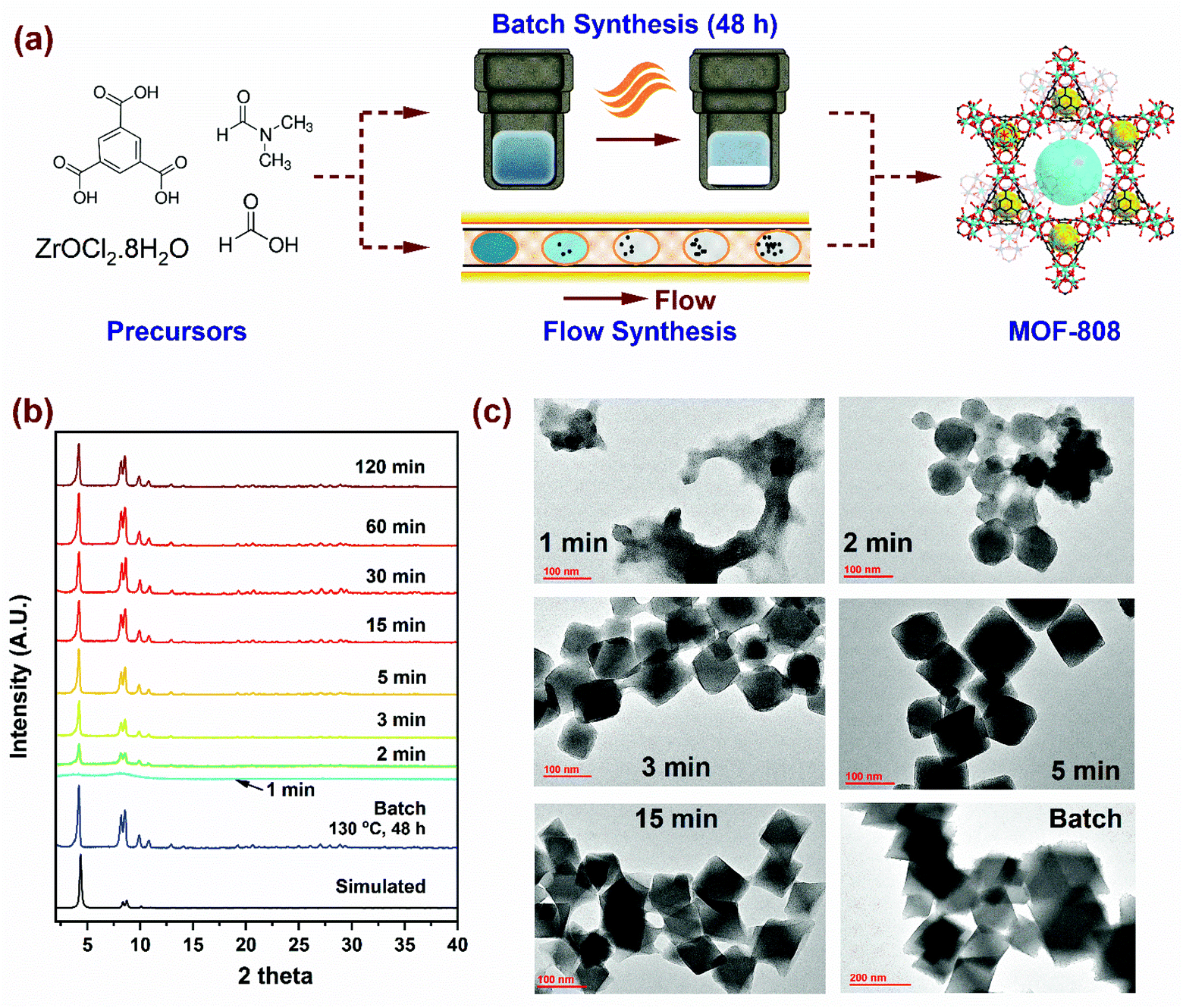 | ||
| Fig. 1 (a) Synthesis scheme for MOF-808 using batch and flow reactors. (b) PXRD patterns showing evolution of crystallinity with residence time for samples synthesized in flow at 150 °C, compared to batch (130 °C, 48 h). (c) TEM images showing morphology of microcrystalline MOF-808 nanoparticles at short residence times (1 to 15 min) and the corresponding batch sample (48 hours). | ||
First, we synthesized MOF-808 in flow conditions at 150 °C and varying residence times from 1 min to 120 min to probe the evolution of crystallinity compared to the benchmark batch reaction conditions (130 °C and 48 h) with identical initial precursor composition as Batch (0.33 mmol of H3BTC and 1.003 mmol of ZrOCl2·8H2O in DMF/formic acid mixture (15 mL/15 mL)). As shown in the powder X-ray diffraction (PXRD) patterns in Fig. 1b, long-range crystalline order started to develop at residence times as low as 2 min in flow and attained full crystallinity at 5 min, beyond which there were no changes detected in the PXRD patterns. Moreover, PXRD patterns showed no mismatch in 2 theta positions, confirming the single-phase nature of microcrystalline powder samples synthesized in flow. SEM images (Fig. S3†) of samples with residence times below 15 min confirmed the octahedral shape of MOF-808 nanoparticles synthesized in flow which is consistent with the batch synthesized sample. TEM images in Fig. 1c show the changes in morphology of MOF-808 nanoparticles at short residence times (1 to 15 min). MOF-808 particles synthesized in flow measured on average ca. 140 nm compared to 360 nm in batch (Fig. S6†). Average crystal sizes were obtained from measurements of ∼80 nanoparticles for each residence time, with the error bars corresponding to one standard deviation (Fig. S4†). The ability to generate smaller monodisperse crystalline particles in our flow reactor is advantageous for practical applications such as adsorption,53 separation,54 and catalysis55 as they improve active surface area and minimize diffusion limitations. Average crystal sizes for Zr-MOFs can be tuned by coordination modulation, where the formate ligand (growth modulator) with similar chemical functionality to the H3BTC linker competes for coordination with the SBU.19,51 Increasing the amount of modulator in the reaction mixture disfavors the formation of nucleation sites resulting in fewer nuclei growing to be larger crystals, thereby explaining the change in crystal sizes. In contrast, a higher linker concentration in the reaction mixture enhances the linker coordination with the SBU by reducing the competitive coordination of the formate ligand, leading to an increase in the number of nucleation sites that grow at a faster rate ultimately resulting in smaller crystal sizes.56 Accordingly, tuning the amount of modulator and linker concentration in the reaction mixture to achieve desired size, porosity, crystallinity and yield with the lowest residence time is imperative from process development standpoint.
We performed experiments by changing one process variable at a time (OVAT) to screen the effects of residence time, volumetric ratio of formic acid (FA) and N,N-dimethylformamide (FA![[thin space (1/6-em)]](https://www.rsc.org/images/entities/char_2009.gif) :DMF), and linker concentration in the reaction mixture. Several studies33,57,58 report on the merits of combining green chemistry principles, such as lower solvent usage, and higher productivity with statistical design of experiments (DoE) for improved process efficiency. The process window for MOF-808 comprises a critical range of parameters within specific reagent molar ratios, residence times, and reaction temperatures that dictate the outcome such as product crystallinity and production rates. Owing to the wide range of synthetic conditions reported in the previous studies for MOF-808,10,12–14,16,53,59 we fixed the reaction temperature to 150 °C and the metal:linker molar ratio (M:L) to a value of 3 for the initial syntheses of microcrystalline samples. In our previous work,60 we investigated the effects of lower synthesis temperatures (110 °C, 120 °C, and 130 °C) on evolution of crystallinity as a function of time. We employed a parameter called ‘extent of crystallization’ (α(t)) that is obtained from the ratio of integrated intensity of a prominent peak at any residence time t to the maximum intensity of the peak after complete crystallization. The sample is crystalline if the value of (α(t)) reaches 1.0. For reaction temperature of 110 °C, residence time of ∼60 min is required for complete crystallization; however, at a reaction temperature of 150 °C, the sample is fully crystalline at ∼5 min. Lower residence times increase the production rates and thereby improve overall process productivity. Temperatures above 150 °C resulted in linker degradation, and hence were not explored further. The precursor solution used for Batch synthesis comprised of M:L = 3 and was heated at 130 °C for 48 hours. In Fig. 2, the variability of product crystallinity was mapped as a function of these process parameters, where labels for every data point represent the relative crystallinity in percentage (% RC). The RC quantifies the amount of crystalline phase present in the synthesized product using PXRD patterns (Fig. S2 and Table S3† provide complete set of analysis and synthesis conditions). Relative crystallinity was determined from a ratio of intensity contributions originating from the crystalline phase that was calculated using an iterative background correction method to the total intensity from the PXRD patterns (eqn (S1) and Fig. S2† provide additional details). The RC of a simulated pattern obtained from single crystal data (Fig. S2a†) was defined to be at 100% and the rest of the samples synthesized in flow were normalized to this value. The outcome was divided into three categories based on RC: (i) samples with >80% RC were classified as crystalline, (ii) samples with 30% < RC < 80% classified as semi-crystalline, and (iii) samples with RC < 30% were classified amorphous.
:DMF), and linker concentration in the reaction mixture. Several studies33,57,58 report on the merits of combining green chemistry principles, such as lower solvent usage, and higher productivity with statistical design of experiments (DoE) for improved process efficiency. The process window for MOF-808 comprises a critical range of parameters within specific reagent molar ratios, residence times, and reaction temperatures that dictate the outcome such as product crystallinity and production rates. Owing to the wide range of synthetic conditions reported in the previous studies for MOF-808,10,12–14,16,53,59 we fixed the reaction temperature to 150 °C and the metal:linker molar ratio (M:L) to a value of 3 for the initial syntheses of microcrystalline samples. In our previous work,60 we investigated the effects of lower synthesis temperatures (110 °C, 120 °C, and 130 °C) on evolution of crystallinity as a function of time. We employed a parameter called ‘extent of crystallization’ (α(t)) that is obtained from the ratio of integrated intensity of a prominent peak at any residence time t to the maximum intensity of the peak after complete crystallization. The sample is crystalline if the value of (α(t)) reaches 1.0. For reaction temperature of 110 °C, residence time of ∼60 min is required for complete crystallization; however, at a reaction temperature of 150 °C, the sample is fully crystalline at ∼5 min. Lower residence times increase the production rates and thereby improve overall process productivity. Temperatures above 150 °C resulted in linker degradation, and hence were not explored further. The precursor solution used for Batch synthesis comprised of M:L = 3 and was heated at 130 °C for 48 hours. In Fig. 2, the variability of product crystallinity was mapped as a function of these process parameters, where labels for every data point represent the relative crystallinity in percentage (% RC). The RC quantifies the amount of crystalline phase present in the synthesized product using PXRD patterns (Fig. S2 and Table S3† provide complete set of analysis and synthesis conditions). Relative crystallinity was determined from a ratio of intensity contributions originating from the crystalline phase that was calculated using an iterative background correction method to the total intensity from the PXRD patterns (eqn (S1) and Fig. S2† provide additional details). The RC of a simulated pattern obtained from single crystal data (Fig. S2a†) was defined to be at 100% and the rest of the samples synthesized in flow were normalized to this value. The outcome was divided into three categories based on RC: (i) samples with >80% RC were classified as crystalline, (ii) samples with 30% < RC < 80% classified as semi-crystalline, and (iii) samples with RC < 30% were classified amorphous.
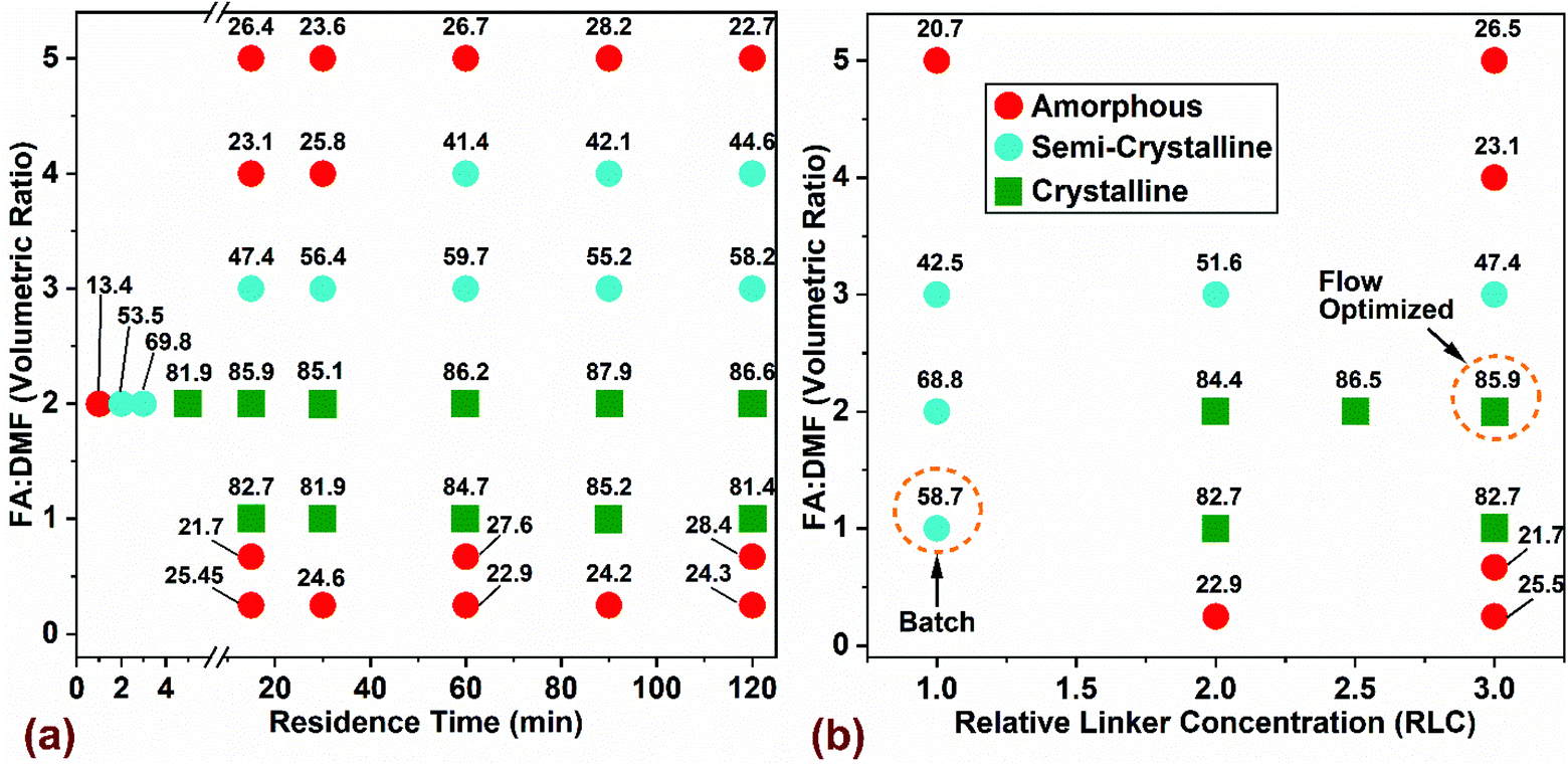 | ||
| Fig. 2 Chemical design space of MOF-808 explored using flow synthesis at 150 °C by varying (a) residence time and solvent composition (FA:DMF) and (b) H3BTC linker concentration and solvent composition (FA:DMF) on product crystallinity at 15 min residence time. The relative linker concentration (RLC) in the precursor mixture in (a) is three times higher than batch composition (RLC = 3), while M:L = 3 is maintained for all conditions explored. Red and blue circles represent amorphous and semi-crystalline regions, while green squares denote crystalline regions in the chemical space. The labels for every data point represents the relative crystallinity in percentage (% RC). | ||
The effect of residence time and FA:DMF on product crystallinity is shown in Fig. 2a. The linker concentration used for all experiments was 0.033 mol (1 mmol in 30 mL precursor), which corresponds to 3 times the value used in benchmark batch synthesis (termed Relative Linker Concentration (RLC) = 3) and a constant molar ratio of metal:linker (M:L = 3) was maintained. RLC is defined as the ratio of moles of H3BTC linker used in the precursor for flow synthesis to the moles of linker used in the benchmark batch synthesis. Residence times were varied from 15–120 min for all conditions explored while short residence times in the range of 1–5 min were run only for the composition with FA:DMF = 2, which yielded solids with the highest level of crystallinity (∼87% RC). At FA:DMF volumetric ratios of 1 and 2, we observed the formation of crystalline MOF-808 at all residence times beyond 5 min, while residence times in the range of 1–3 min led to amorphous and semi-crystalline products (Fig. 2a). Increasing the amount of formic acid in the precursor mixture (FA:DMF = 3) resulted in a semi-crystalline product at all residence times, possibly due to competitive coordination of the formate ligand with the SBU which reduces the chances of linker coordination, resulting in defects and a low crystalline product. A further increase in the amount of formic acid (FA:DMF = 4) yields amorphous solids at residence times below 30 min and a semi-crystalline product showing short range order with increasing residence time. These results suggest that longer induction periods may be necessary to overcome the reduced rate of nucleation and crystal growth due to the influence of excess formate ions in the precursor solution reported previously.19,54 The highest level of formic acid (FA:DMF = 5) in the precursor mixture resulted in amorphous solids at all residence times, due to the H3BTC linker precipitating out of the solution and changing the precursor composition and coordination equilibria required to crystallize MOF-808. Lower levels of formic acid (FA:DMF = 0.67, and 0.25) generated amorphous solids in the form of a dense residue resulting from fast coordination reactions between the linker and SBU – lacking long-range order.51
The influence of linker concentration and volumetric ratio of FA:DMF on MOF-808 crystallinity (at residence time of 15 min and a constant M:L = 3) is shown in Fig. 2b. Flow reactors can usually operate at higher concentrations than batch reactors, offering great benefits for increasing process productivity by using higher concentration of metal salt and linker while maintaining similar yields and crystallinity as reported in previous studies.52,61,62 Accordingly, we explored the effect of linker concentration on crystallinity of MOF (Fig. 2b). Optimization of the linker concentration and solvent composition in flow synthesis was done relative to the conventional batch crystallization mixture12 (FA:DMF = 1 and RLC = 1), highlighted as ‘Batch’ in Fig. 2b. Interestingly, the standard batch composition did not yield any solids in flow synthesis, which led us to increase the linker concentration in discrete steps of the initial composition by 2-, 2.5- and 3-times the amount used in batch (per unit mass) to investigate the effects of higher linker concentration in the reaction mixture. Crystalline solids were obtained at reaction conditions with FA:DMF = 1, and 2, and RLC in the range of 2 to 3. In particular, the composition with RLC of 3, yielded a three-fold increase in the amount of crystalline solids on a volumetric basis of the precursor mixture. This synthesis condition is labelled ‘Flow Optimized’ (Fig. 2b). This condition resulted in lower solvent amounts required per unit mass of solids synthesized and a lower residence time for crystallization, thereby improving the overall process productivity. Other compositions explored in the synthesis space resulted in semi-crystalline or amorphous solids. Increasing the RLC beyond 3 led to incomplete dissolution of the metal salt and linker in the precursor mixture and thus were not explored. While tuning various synthetic parameters, an important metric to monitor would be the molar ratio of modulator (Formic Acid) and the metal salt (termed ‘FA:M’) used in the precursor mixture, stated in Table S3† for all compositions explored in the study. The composition used in batch had a FA:M molar ratio of 396, while that in flow was 176. Crystalline products were obtained in flow synthesis only in a narrow range of FA:M molar ratios between 176 to 264. In order to illustrate a wider chemical design space to map the influence of the salt, linker, and modulator on the crystallinity of MOF-808, we constructed a ternary phase diagram (shown in Fig. S7†) to identify the regions that yield crystalline product. The axes in the ternary diagram represent mole fractions of the FA modulator, H3BTC linker, and the Zr metal salt; all the explored compositions were subjected to 150 °C and 15 min residence time in the flow reactor. The molar ratios of FA:M in compositions with M:L = 1 were either significantly high (∼1050) or below 170, which resulted in a predominantly semi-crystalline or amorphous product under the residence time explored. While compositions with M:L = 3 represent the data shown in Fig. 2b. Tables S4 and S5† provide calculations for yield and productivity for batch and flow syntheses. The yield was calculated based on the conversion of ZrOCl2·8H2O into MOF-808 (Table S4†). The yield obtained in flow synthesis was ∼80% while batch synthesis resulted in ∼75% which is consistent with previous studies.10,12,53 The maximum productivity achieved in batch synthesis was 335.5 kgMOF m−3 day−1 while flow synthesis at a residence time of 5 min resulted in 95155 kgMOF m−3 day−1, representing a two order of magnitude increase in productivity.
Samples synthesized in flow at optimal reaction conditions were characterized to evaluate surface area, porosity, and thermal stability parameters, which were then compared to those for the benchmark sample synthesized in batch. As shown in Fig. 3a, the N2 adsorption isotherms collected at 77 K for all samples (except the 1 min sample) were of Type I with a step at P/P0 ∼ 0.03, consistent with data reported in previous studies.10–12,63 The samples synthesized in flow at residence times beyond 15 min exhibited slightly higher adsorption characteristics compared to the samples with residence times below 5 min, possibly due to the former having higher crystallinity with a lower number of defects. To satisfy the first criteria of the BET equation,64 isotherm data lying within 0.05–0.15 P/P0 were selected for curve-fitting with R2 > 0.997 (Fig. S8†). The BET surface area (Fig. 4a) showed a correlation with residence time values from ∼1600 m2 g−1 to ∼2000 m2 g−1 with increasing residence time from 5 min to 15 min, beyond which it remained constant. The BET surface area for the batch synthesized sample was ∼1900 m2 g−1 similar to that reported in previous studies.10,14,65 The pore size distribution (PSD) was calculated using non-local density functional theory (NLDFT) based on the carbon slit-pore model as shown in Fig. 3b. The average diameter of pores for all samples was ∼16.8 Å. Samples with 3 and 5 min residence time showed a lower density of pore sizes beyond 16 Å. Thermogravimetric analysis data (TGA) showing weight loss as a function of temperature is presented in Fig. S9† for activated samples. An initial weight loss of ∼3% below 140 °C could be attributed to the loss of physisorbed water, while an additional ∼18% weight loss was observed due to loss of coordinated water and formate ions on the SBU up to 300 °C.65 A significant weight loss of ∼33% was observed at ∼500 °C that resulted from decomposition of the organic linkers in the framework as shown previously.66 Owing to the amorphous nature of 1 min sample, it showed a steady weight loss without any distinct features common to those in crystalline samples. The residual material in the form of white powder obtained >600 °C is composed of ZrO2 formed after framework decomposition as reported by Liu et al.65
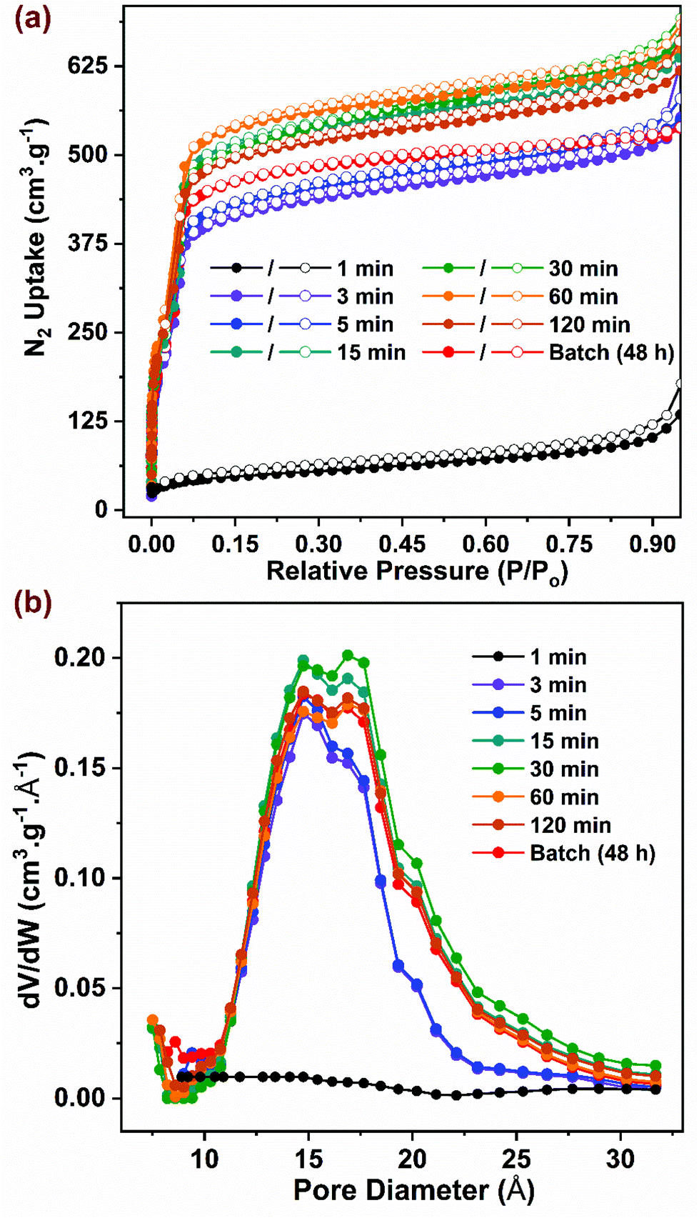 | ||
| Fig. 3 (a) N2 adsorption (closed symbol) and desorption (open symbol) isotherms at 77 K for samples synthesized in batch and flow. (b) Pore size distribution (PSD) for all samples computed using NLDFT method. | ||
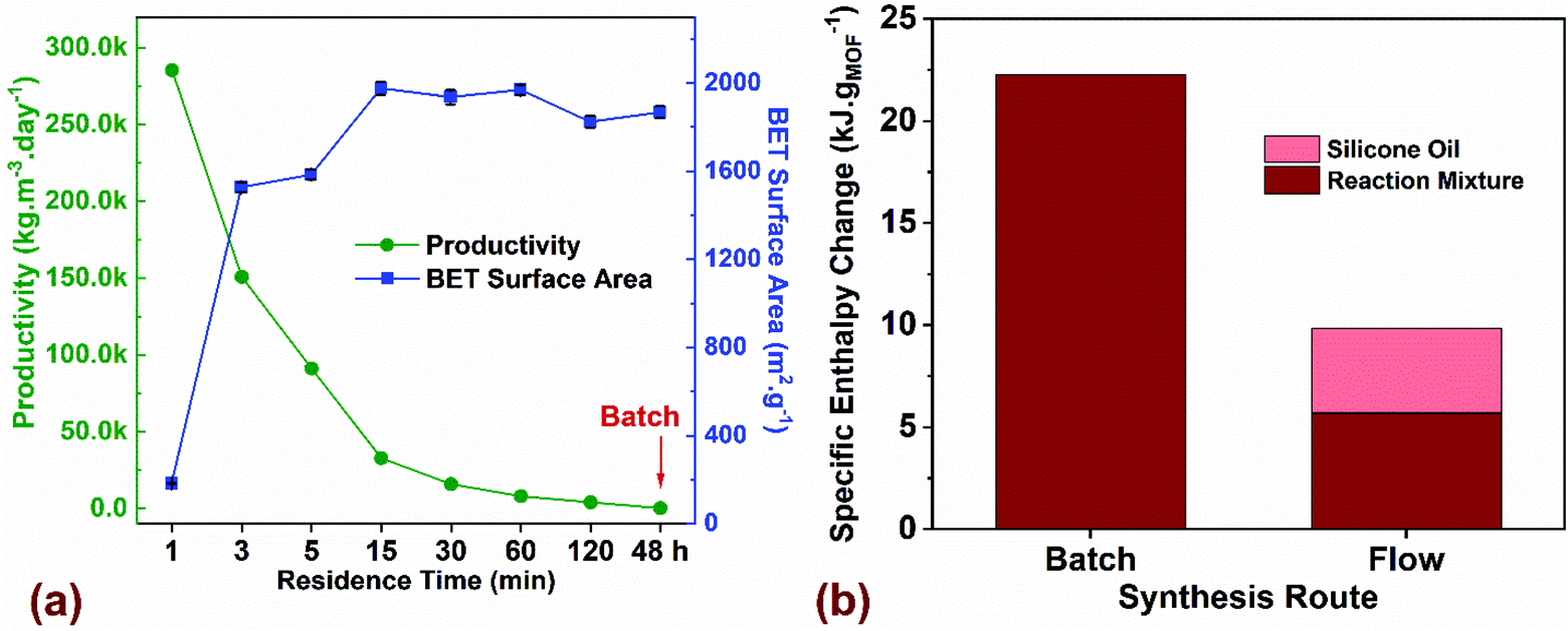 | ||
| Fig. 4 (a) Comparison of process productivity (kgMOF m−3 day−1) and BET surface area (m2 g−1) for flow synthesized MOF-808 as a function of residence time (min) compared to batch with a reaction time of 48 h. (b) Thermal energy input required to crystallize a gram of MOF for batch and flow syntheses. Additional details on the TEA model and assumptions are listed in ESI.† | ||
Next, we performed a preliminary techno-economic analysis (TEA) to highlight energy- and cost-savings achieved using the flow process compared to batch for a laboratory-scale synthesis route. Although the number of MOF synthesis reports is extensive, there is a paucity of studies that perform cost and energy analyses of the synthesis process with the goal to improve overall productivity by quantifying the cost drivers and reducing process waste.67,68 In a continuous manufacturing environment, comparing process parameters such as productivity (kgMOF m−3 day−1) with critical attributes of the synthesized product such as BET surface area (m2 g−1), provides a metric for tailoring the manufacturing output with the desired product quality. Fig. 4a plots productivity and surface area for the MOF-808 samples synthesized in flow and batch as a function of residence time. If high surface areas ∼2000 m2 g−1 were favored, our results indicate that a residence time of 15 min in flow is preferred, thus resulting in a productivity of 31730 kgMOF m−3 day−1. An increase in residence time beyond 15 min drastically reduces the productivity while resulting in roughly similar surface areas of the synthesized MOF. A reduction in residence time to 5 min is accompanied by lower surface area of the MOF ∼ 1600 m2 g−1 and a corresponding increase in productivity to 95155 kgMOF m−3 day−1. Residence times below 3 min result in a semi-crystalline or amorphous product (Fig. 2a) and were not considered for further investigation. Residence times greater than 120 min result in productivities comparable to batch process making them unattractive to pursue. The key translational piece for widespread use of MOFs in different technology platforms is the ability to manufacture at desired scale with market prices that are not prohibitive.38,69 The majority of lab-scale MOF syntheses reported in the literature are carried out in batch reactors that synthesize MOFs at the hundred milligram scale, and even at this scale, it is crucial to estimate mass- and energy-balances along with direct costs of synthesis before scale-up to a kg or ton scale can be considered. For the laboratory optimized batch and flow syntheses, we employed a process-based cost estimation methodology to access production costs, which mimics the actual steps of synthesis (from raw materials to finished product) and determines the final cost by summing individual costs incurred in each of the steps.70 In order to streamline the techno-economic analysis (TEA), we only consider production costs directly related to the MOF synthesis and ignore indirect costs and labor costs. The system boundary for the TEA, the production scenarios, the methodology for estimating process costs (materials, energy, and equipment), along with the electrical energy consumed by the process is described in section 3 of the ESI.†
We performed energy balances for both batch and flow processes by estimating specific enthalpy changes (kJ gMOF−1), defined in terms of thermal energy input (kJ) required for heating a specific amount of the reaction mixture from room temperature (20 °C) to the reaction setpoint temperature (130 °C for Batch and 150 °C for Flow) to crystallize a gram of MOF (Fig. 4b). Specific heat capacity c (J kg−1 K−1) and density ρ (g mL−1) values for the reaction mixtures used in batch and flow were estimated from the process modelling software ASPEN Plus V10 (Table S10†). Results showed that the hhheat input required only for the reaction mixture is 4x higher for batch synthesis compared to flow. For a biphasic slug flow system in our flow reactor, we use a volumetric flow ratio of 2:1 for the reaction mixture to silicone oil for maximizing the amount of reaction mixture injected into the reactor without affecting the mixing characteristics in the slugs. If the energy for heating the silicone oil (continuous phase) is added to the energy required for heating the reaction mixture in flow, the total heat input for the flow process is ∼10 kJ gMOF−1, which corresponds to less than half the value for batch synthesis. The energy intensity of the process in terms of electrical energy consumed to synthesize a gram of MOF (kW h g−1) is plotted in Fig. S14,† which accounts for the total electricity consumption in all unit operations, along with the corresponding process emissions (kg CO2-eq g−1). Since electricity is the only form of energy input required for the synthesis, process emissions originate only from the electricity grid and vary linearly as a function of energy consumed in the process. Carbon intensity of the ISO-NE electricity grid in the form of annual average greenhouse gas (GHG) emissions per kW h generated was reported to be 310 g kW h−1 in 2017.71 Energy intensity of the flow synthesis compared to batch is lower by two orders of magnitude, demonstrating significant improvements in energy efficiency achieved in flow. We recognize that the TEA assessment to translate a lab-scale synthesis to a large-scale chemical process is very complex. Yet, given the large number of functional MOFs reported in the literature, a critical assessment and optimization of manufacturing routes in a lab-scale environment serves as a valuable initial prerequisite for sustainable industrial-scale synthesis paving the way for advent of low-cost MOFs in commercial technologies.
Conclusions
We report an optimized manufacturing process using continuous flow reactors for the production of MOF-808. Critical process parameters such as residence time, linker concentration, as well as volumetric ratios of modulator and solvent were rapidly screened to assess their influence on crystallinity and surface area. Optimized synthetic conditions in flow led to a reduction in the use of DMF by ∼84% and formic acid by ∼67% on a volumetric basis – highlighting the direct benefits of flow synthesis for process intensification. Highly crystalline monodisperse MOF-808 nanoparticles were synthesized in a residence time of 5 min in flow compared to 48 h in batch, resulting in a productivity of 95155 kg m−3 day−1, which represents a two order of magnitude increase to that in batch (335.5 kg m−3 day−1). A TEA model was used to evaluate cost drivers and energy and mass balances involving lab-scale synthesis of MOFs. Under a continuous production environment, solvent costs dominate the synthesis costs and a further reduction in cost structure can be achieved by minimizing the use of solvents or employing an efficient solvent recycling strategy. The mminimum cost of manufacturing MOF-808 in a laboratory-scale flow synthesis route was ∼$3 per g, representing a significant decrease in cost compared to current MOF synthesis prices. The methodology used in the TEA highlights the critical need to assess and optimize synthesis route to manufacture MOFs at low-cost to increase their viable use in a wide range of established and emerging applications.
Author contributions
S. Bagi conceived and performed all experimental work for materials synthesis, characterization, TEA, and prepared the manuscript. S. Yuan, S. Rojas-Buzo, and Y. Shao-Horn participated in the discussion of the data and provided intellectual contributions for the study. Y. Román-Leshkov supervised and guided the overall project. All authors have given approval to the final version of the manuscript.Conflicts of interest
The authors declare no competing financial interest. Reference to any commercial product or process does not constitute its endorsement.Acknowledgements
The authors would like to thank Dr Charles Settens for fruitful discussions related to quantification of relative crystallinity using PXRD data, Dr Daniel Consoli for inputs on the TEA model, and Dr Yong Zhang for technical assistance with the TEM. We thank the U.S. Department of Energy, Office of Basic Energy Sciences under Award DE-SC0016214 for support. We also thank the Toyota Research Institute through the Accelerated Materials Design and Discovery program for support.References
- Y. Bai, Y. Dou, L.-H. Xie, W. Rutledge, J.-R. Li and H.-C. Zhou, Zr-based metal–organic frameworks: design, synthesis, structure, and applications, Chem. Soc. Rev., 2016, 45(8), 2327–2367, 10.1039/c5cs00837a.
- H. C. Zhou, J. R. Long and O. M. Yaghi, Introduction to Metal-Organic Frameworks, Chem. Rev., 2012, 112(2), 673–674, DOI:10.1021/cr300014x.
- C. H. Hendon, A. J. Rieth, M. D. Korzyński and M. Dincă, Grand Challenges and Future Opportunities for Metal–Organic Frameworks, ACS Cent. Sci., 2017, 3(6), 554–563, DOI:10.1021/acscentsci.7b00197.
- K.-S. Lin, A. K. Adhikari, C.-N. Ku, C.-L. Chiang and H. Kuo, Synthesis and characterization of porous HKUST-1 metal organic frameworks for hydrogen storage, Int. J. Hydrogen Energy, 2012, 37(18), 13865–13871, DOI:10.1016/j.ijhydene.2012.04.105.
- W. Chen and C. S. Wu, Synthesis, functionalization, and applications of metal-organic frameworks in biomedicine, Dalton Trans., 2018, 47(7), 2114–2133, 10.1039/c7dt04116k.
- P. Horcajada, R. Gref, T. Baati, P. K. Allan, G. Maurin, P. Couvreur, G. Ferey, R. E. Morris and C. Serre, Metal-Organic Frameworks in Biomedicine, Chem. Rev., 2012, 112(2), 1232–1268, DOI:10.1021/cr200256v.
- J. Lee, O. K. Farha, J. Roberts, K. A. Scheidt, S. T. Nguyen and J. T. Hupp, Metal-organic framework materials as catalysts, Chem. Soc. Rev., 2009, 38(5), 1450–1459, 10.1039/b807080f.
- P. Z. Moghadam, A. Li, S. B. Wiggin, A. Tao, A. G. P. Maloney, P. A. Wood, S. C. Ward and D. Fairen-Jimenez, Development of a Cambridge Structural Database Subset: A Collection of Metal–Organic Frameworks for Past, Present, and Future, Chem. Mater., 2017, 29(7), 2618–2625, DOI:10.1021/acs.chemmater.7b00441.
- S. Yuan, L. Feng, K. Wang, J. Pang, M. Bosch, C. Lollar, Y. Sun, J. Qin, X. Yang, P. Zhang, Q. Wang, L. Zou, Y. Zhang, L. Zhang, Y. Fang, J. Li and H.-C. Zhou, Stable Metal-Organic Frameworks: Design, Synthesis, and Applications, Adv. Mater., 2018, 30(37), 1704303, DOI:10.1002/adma.201704303.
- H. Furukawa, F. Gandara, Y. B. Zhang, J. C. Jiang, W. L. Queen, M. R. Hudson and O. M. Yaghi, Water Adsorption in Porous Metal-Organic Frameworks and Related Materials, J. Am. Chem. Soc., 2014, 136(11), 4369–4381, DOI:10.1021/ja500330a.
- W. Liang, H. Chevreau, F. Ragon, P. D. Southon, V. K. Peterson and D. M. D'Alessandro, Tuning pore size in a zirconium–tricarboxylate metal–organic framework, CrystEngComm, 2014, 16(29), 6530–6533, 10.1039/c4ce01031k.
- J. Jiang, F. Gándara, Y.-B. Zhang, K. Na, O. M. Yaghi and W. G. Klemperer, Superacidity in Sulfated Metal–Organic Framework-808, J. Am. Chem. Soc., 2014, 136(37), 12844–12847, DOI:10.1021/ja507119n.
- J. Baek, B. Rungtaweevoranit, X. Pei, M. Park, S. C. Fakra, Y.-S. Liu, R. Matheu, S. A. Alshmimri, S. Alshehri, C. A. Trickett, G. A. Somorjai and O. M. Yaghi, Bioinspired Metal–Organic Framework Catalysts for Selective Methane Oxidation to Methanol, J. Am. Chem. Soc., 2018, 140(51), 18208–18216, DOI:10.1021/jacs.8b11525.
- Y. Peng, H. Huang, Y. Zhang, C. Kang, S. Chen, L. Song, D. Liu and C. Zhong, A versatile MOF-based trap for heavy metal ion capture and dispersion, Nat. Commun., 2018, 9, 187, DOI:10.1038/s41467-017-02600-2.
- J. E. Efome, D. Rana, T. Matsuura and C. Q. Lan, Metal–organic frameworks supported on nanofibers to remove heavy metals, J. Mater. Chem. A, 2018, 6(10), 4550–4555, 10.1039/c7ta10428f.
- C. A. Trickett, T. M. Osborn Popp, J. Su, C. Yan, J. Weisberg, A. Huq, P. Urban, J. Jiang, M. J. Kalmutzki, Q. Liu, J. Baek, M. P. Head-Gordon, G. A. Somorjai, J. A. Reimer and O. M. Yaghi, Identification of the strong Brønsted acid site in a metal–organic framework solid acid catalyst, Nat. Chem., 2018, 11(2), 170–176, DOI:10.1038/s41557-018-0171-z.
- H.-Q. Zheng, C.-Y. Liu, X.-Y. Zeng, J. Chen, J. Lü, R.-G. Lin, R. Cao, Z.-J. Lin and J.-W. Su, MOF-808: A Metal–Organic Framework with Intrinsic Peroxidase-Like Catalytic Activity at Neutral pH for Colorimetric Biosensing, Inorg. Chem., 2018, 57(15), 9096–9104, DOI:10.1021/acs.inorgchem.8b01097.
- S. Rojas-Buzo, P. García-García and A. Corma, Zr-MOF-808@MCM-41 catalyzed phosgene-free synthesis of polyurethane precursors, Catal. Sci. Technol., 2019, 9(1), 146–156, 10.1039/c8cy02235f.
- A. Schaate, P. Roy, A. Godt, J. Lippke, F. Waltz, M. Wiebcke and P. Behrens, Modulated Synthesis of Zr-Based Metal-Organic Frameworks: From Nano to Single Crystals, Chem. – Eur. J., 2011, 17(24), 6643–6651, DOI:10.1002/chem.201003211.
- G. M. Monsalve-Bravo, H. M. Moscoso-Vasquez and H. Alvarez, Scaleup of Batch Reactors Using Phenomenological-Based Models, Ind. Eng. Chem. Res., 2014, 53(22), 9439–9453, DOI:10.1021/ie500587r.
- Z. D. Liu, J. Zhu, C. Peng, T. Wakihara and T. Okubo, Continuous flow synthesis of ordered porous materials: from zeolites to metal-organic frameworks and mesoporous silica, React. Chem. Eng., 2019, 4(10), 1699–1720, 10.1039/c9re00142e.
- M. Rubio-Martinez, T. D. Hadley, M. P. Batten, K. Constanti-Carey, T. Barton, D. Marley, A. Monch, K. S. Lim and M. R. Hill, Scalability of Continuous Flow Production of Metal-Organic Frameworks, ChemSusChem, 2016, 9(9), 938–941, DOI:10.1002/cssc.201501684.
- Z. D. Liu, J. Zhu, T. Wakihara and T. Okubo, Ultrafast synthesis of zeolites: breakthrough, progress and perspective, Inorg. Chem. Front., 2019, 6(1), 14–31, 10.1039/c8qi00939b.
- J. L. Steinbacher and D. T. McQuade, Polymer chemistry in flow: New polymers, beads, capsules, and fibers, J. Polym. Sci., Part A: Polym. Chem., 2006, 44(22), 6505–6533, DOI:10.1002/pola.21630.
- H. Kim, A. Nagaki and J.-I. Yoshida, A flow-microreactor approach to protecting-group-free synthesis using organolithium compounds, Nat. Commun., 2011, 2, 264, DOI:10.1038/ncomms1264.
- A. Adamo, R. L. Beingessner, M. Behnam, J. Chen, T. F. Jamison, K. F. Jensen, J. C. M. Monbaliu, A. S. Myerson, E. M. Revalor, D. R. Snead, T. Stelzer, N. Weeranoppanant, S. Y. Wong and P. Zhang, On-demand continuous-flow production of pharmaceuticals in a compact, reconfigurable system, Science, 2016, 352(6281), 61–67, DOI:10.1126/science.aaf1337.
- J.-I. Yoshida, H. Kim and A. Nagaki, Green and Sustainable Chemical Synthesis Using Flow Microreactors, ChemSusChem, 2011, 4(3), 331–340, DOI:10.1002/cssc.201000271.
- B. Pieber, M. Shalom, M. Antonietti, P. H. Seeberger and K. Gilmore, Continuous Heterogeneous Photocatalysis in Serial Micro-Batch Reactors, Angew. Chem., Int. Ed., 2018, 57(31), 9976–9979, DOI:10.1002/anie.201712568.
- M. A. Cummings, M. Haaf, D. T. McQuade, J. Steinbacher, S. L. Poe and R. Moy, Precipitate forming reactions in a simplified microfluidic device, Abstr. Pap. Am. Chem. Soc., 2006, 231 Search PubMed.
- A. Gunther and K. F. Jensen, Multiphase microfluidics: from flow characteristics to chemical and materials synthesis, Lab Chip, 2006, 6(12), 1487–1503, 10.1039/b609851g.
- J. Zhang, K. Wang, A. R. Teixeira, K. F. Jensen and G. Luo, Design and Scaling Up of Microchemical Systems: A Review, Annu. Rev. Chem. Biomol. Eng., 2017, 8(1), 285–305, DOI:10.1146/annurev-chembioeng-060816-101443.
- N. Kockmann and D. M. Roberge, Harsh Reaction Conditions in Continuous-Flow Microreactors for Pharmaceutical Production, Chem. Eng. Technol., 2009, 32(11), 1682–1694, DOI:10.1002/ceat.200900355.
- P. M. Murray, F. Bellany, L. Benhamou, D.-K. Bučar, A. B. Tabor and T. D. Sheppard, The application of design of experiments (DoE) reaction optimisation and solvent selection in the development of new synthetic chemistry, Org. Biomol. Chem., 2016, 14(8), 2373–2384, 10.1039/c5ob01892g.
- D. E. Fitzpatrick and S. V. Ley, Engineering chemistry: integrating batch and flow reactions on a single, automated reactor platform, React. Chem. Eng., 2016, 1(6), 629–635, 10.1039/c6re00160b.
- P. A. Bayliss, I. A. Ibarra, E. Pérez, S. Yang, C. C. Tang, M. Poliakoff and M. Schröder, Synthesis of metal–organic frameworks by continuous flow, Green Chem., 2014, 16(8), 3796–3802, 10.1039/c4gc00313f.
- M. P. Batten, M. Rubio-Martinez, T. Hadley, K. C. Carey, K. S. Lim, A. Polyzos and M. R. Hill, Continuous flow production of metal-organic frameworks, Curr. Opin. Chem. Eng., 2015, 8, 55–59, DOI:10.1016/j.coche.2015.02.001.
- H. Reinsch, S. Waitschat, S. M. Chavan, K. P. Lillerud and N. Stock, A Facile “Green” Route for Scalable Batch Production and Continuous Synthesis of Zirconium MOFs, Eur. J. Inorg. Chem., 2016,(27), 4490–4498, DOI:10.1002/ejic.201600295.
- M. Rubio-Martinez, C. Avci-Camur, A. W. Thornton, I. Imaz, D. Maspoch and M. R. Hill, New synthetic routes towards MOF production at scale, Chem. Soc. Rev., 2017, 46(11), 3453–3480, 10.1039/c7cs00109f.
- S. Waitschat, M. T. Wharmby and N. Stock, Flow-synthesis of carboxylate and phosphonate based metal-organic frameworks under non-solvothermal reaction conditions, Dalton Trans., 2015, 44(24), 11235–11240, 10.1039/c5dt01100k.
- G. H. Albuquerque, R. C. Fitzmorris, M. Ahmadi, N. Wannenmacher, P. K. Thallapally, B. P. McGrail and G. S. Herman, Gas–liquid segmented flow microwave-assisted synthesis of MOF-74(Ni) under moderate pressures, CrystEngComm, 2015, 17(29), 5502–5510, 10.1039/c5ce00848d.
- E. G. Rasmussen, J. Kramlich and I. V. Novosselov, Scalable Continuous Flow Metal–Organic Framework (MOF) Synthesis Using Supercritical CO2, ACS Sustainable Chem. Eng., 2020, 8(26), 9680–9689, DOI:10.1021/acssuschemeng.0c01429.
- H. Gao, Y. Luan, K. Chaikittikul, W. Dong, J. Li, X. Zhang, D. Jia, M. Yang and G. Wang, A Facile in Situ Self-Assembly Strategy for Large-Scale Fabrication of CHS@MOF Yolk/Shell Structure and Its Catalytic Application in a Flow System, ACS Appl. Mater. Interfaces, 2015, 7(8), 4667–4674, DOI:10.1021/am508079j.
- B. He, M. M. Sadiq, M. P. Batten, K. Suzuki, M. Rubio-Martinez, J. Gardiner and M. R. Hill, Continuous Flow Synthesis of a Zr Magnetic Framework Composite for Post–Combustion CO2 Capture, Chem. – Eur. J., 2019, 25(57), 13184–13188, DOI:10.1002/chem.201902560.
- P. A. Bayliss, I. A. Ibarra, E. Perez, S. H. Yang, C. C. Tang, M. Poliakoff and M. Schroder, Synthesis of metal-organic frameworks by continuous flow, Green Chem., 2014, 16(8), 3796–3802, 10.1039/c4gc00313f.
- Y. Wang, L. Li, L. Yan, L. Cao, P. Dai, X. Gu and X. Zhao, Continuous synthesis for zirconium metal-organic frameworks with high quality and productivity via microdroplet flow reaction, Chin. Chem. Lett., 2018, 29(6), 849–853, DOI:10.1016/j.cclet.2017.09.057.
- H. Song, D. L. Chen and R. F. Ismagilov, Reactions in droplets in microflulidic channels, Angew. Chem., Int. Ed., 2006, 45(44), 7336–7356, DOI:10.1002/anie.200601554.
- M. N. Kashid and D. W. Agar, Hydrodynamics of liquid-liquid slug flow capillary microreactor: Flow regimes, slug size and pressure drop, Chem. Eng. J., 2007, 131(1–3), 1–13, DOI:10.1016/j.cej.2006.11.020.
- A. Ufer, M. Mendorf, A. Ghaini and D. W. Agar, Liquid-Liquid Slug Flow Capillary Microreactor, Chem. Eng. Technol., 2011, 34(3), 353–360, DOI:10.1002/ceat.201000334.
- J. P. Patterson, P. Abellan, M. S. Denny, C. Park, N. D. Browning, S. M. Cohen, J. E. Evans and N. C. Gianneschi, Observing the Growth of Metal-Organic Frameworks by in Situ Liquid Cell Transmission Electron Microscopy, J. Am. Chem. Soc., 2015, 137(23), 7322–7328, DOI:10.1021/jacs.5b00817.
- H.-H. Shi, Y. Xiao, S. Ferguson, X. Huang, N. Wang and H.-X. Hao, Progress of crystallization in microfluidic devices, Lab Chip, 2017, 17(13), 2167–2185, 10.1039/c6lc01225f.
- G. Zahn, P. Zerner, J. Lippke, F. L. Kempf, S. Lilienthal, C. A. Schröder, A. M. Schneider and P. Behrens, Insight into the mechanism of modulated syntheses: in situ synchrotron diffraction studies on the formation of Zr-fumarate MOF, CrystEngComm, 2014, 16(39), 9198–9207, 10.1039/c4ce01095g.
- S. Bagi, A. M. Wright, J. Oppenheim, M. Dincă and Y. Román-Leshkov, Accelerated Synthesis of a Ni2Cl2(BTDD) Metal–Organic Framework in a Continuous Flow Reactor for Atmospheric Water Capture, ACS Sustainable Chem. Eng., 2021, 9(11), 3996–4003, DOI:10.1021/acssuschemeng.0c07055.
- Z.-Q. Li, J.-C. Yang, K.-W. Sui and N. Yin, Facile synthesis of metal-organic framework MOF-808 for arsenic removal, Mater. Lett., 2015, 160, 412–414, DOI:10.1016/j.matlet.2015.08.004.
- M. Sindoro, N. Yanai, A.-Y. Jee and S. Granick, Colloidal-Sized Metal–Organic Frameworks: Synthesis and Applications, Acc. Chem. Res., 2013, 47(2), 459–469, DOI:10.1021/ar400151n.
- M. Hartmann, A. G. Machoke and W. Schwieger, Catalytic test reactions for the evaluation of hierarchical zeolites, Chem. Soc. Rev., 2016, 45(12), 3313–3330, 10.1039/c5cs00935a.
- P. Y. Moh, M. Brenda, M. W. Anderson and M. P. Attfield, Crystallisation of solvothermally synthesised ZIF-8 investigated at the bulk, single crystal and surface level, CrystEngComm, 2013, 15, 9672–9678, 10.1039/c3ce40943k.
- G. D. Bowden, B. J. Pichler and A. Maurer, A Design of Experiments (DoE) Approach Accelerates the Optimization of Copper-Mediated 18F-Fluorination Reactions of Arylstannanes, Sci. Rep., 2019, 9, 11370, DOI:10.1038/s41598-019-47846-6.
- S. A. Weissman and N. G. Anderson, Design of Experiments (DoE) and Process Optimization. A Review of Recent Publications, Org. Process Res. Dev., 2014, 19(11), 1605–1633, DOI:10.1021/op500169m.
- H. Reinsch, S. Waitschat, S. M. Chavan, K. P. Lillerud and N. Stock, A Facile “Green” Route for Scalable Batch Production and Continuous Synthesis of Zirconium MOFs, Eur. J. Inorg. Chem., 2016, 2016(27), 4490–4498, DOI:10.1002/ejic.201600295.
- S. D. Bagi, A. S. Myerson and Y. Román-Leshkov, Solvothermal Crystallization Kinetics and Control of Crystal Size Distribution of MOF-808 in a Continuous Flow Reactor, Cryst. Growth Des., 2021, 21(11), 6529–6536, DOI:10.1021/acs.cgd.1c00968.
- S. Tummala, A. Ramirez, S. Srivastava and D. M. Hallow, Development of design space for reaction steps: approaches and case studies for impurity control, Chem. Eng. Pharm. Ind., 2019, 1091–1122 Search PubMed.
- T. Illg, P. Lob and V. Hessel, Flow chemistry using milli- and microstructured reactors-From conventional to novel process windows, Bioorg. Med. Chem., 2010, 18(11), 3707–3719, DOI:10.1016/j.bmc.2010.03.073.
- M. Thommes, K. Kaneko, A. V. Neimark, J. P. Olivier, F. Rodriguez-Reinoso, J. Rouquerol and K. S. W. Sing, Physisorption of gases, with special reference to the evaluation of surface area and pore size distribution (IUPAC Technical Report), Pure Appl. Chem., 2015, 87(9–10), 1051–1069, DOI:10.1515/pac-2014-1117.
- D. A. Gómez-Gualdrón, P. Z. Moghadam, J. T. Hupp, O. K. Farha and R. Q. Snurr, Application of Consistency Criteria To Calculate BET Areas of Micro- And Mesoporous Metal–Organic Frameworks, J. Am. Chem. Soc., 2015, 138(1), 215–224, DOI:10.1021/jacs.5b10266.
- H. Liu, Z. Zhang, J. Tang, Z. Fei, Q. Liu, X. Chen, M. Cui and X. Qiao, Quest for pore size effect on the catalytic property of defect-engineered MOF-808-SO4 in the addition reaction of isobutylene with ethylene glycol, J. Solid State Chem., 2019, 269, 9–15, DOI:10.1016/j.jssc.2018.07.030.
- L. Valenzano, B. Civalleri, S. Chavan, S. Bordiga, M. H. Nilsen, S. Jakobsen, K. P. Lillerud and C. Lamberti, Disclosing the Complex Structure of UiO-66 Metal Organic Framework: A Synergic Combination of Experiment and Theory, Chem. Mater., 2011, 23(7), 1700–1718, DOI:10.1021/cm1022882.
- F. Benaskar, A. Ben-Abdelmoumen, N. G. Patil, E. V. Rebrov, J. Meuldijk, L. A. Hulshof, V. Hessel, U. Krtschil and J. C. Schouten, Cost Analysis for a Continuously Operated Fine Chemicals Production Plant at 10 Kg/Day Using a Combination of Microprocessing and Microwave Heating, J. Flow Chem., 2011, 1(2), 74–89, DOI:10.1556/jfchem.2011.00015.
- D. DeSantis, J. A. Mason, B. D. James, C. Houchins, J. R. Long and M. Veenstra, Techno-economic Analysis of Metal–Organic Frameworks for Hydrogen and Natural Gas Storage, Energy Fuels, 2017, 31(2), 2024–2032, DOI:10.1021/acs.energyfuels.6b02510.
- P. W. Dunne, E. Lester and R. I. Walton, Towards scalable and controlled synthesis of metal-organic framework materials using continuous flow reactors, React. Chem. Eng., 2016, 1(4), 352–360, 10.1039/c6re00107f.
- C. Smart, G. Reese, L. Adams, A. Batchelor and A. Redrick, Process-Based Cost Modeling, J. Param., 2007, 26(1), 79–100, DOI:10.1080/10157891.2007.10462279.
- 2019 ISO New England Electric Generator Air Emissions Report, ISO New England Inc. System Planning, https://www.iso-ne.com/system-planning/system-plans-studies/emissions/, (accessed October 2021).
Footnote |
| † Electronic supplementary information (ESI) available. See DOI: 10.1039/d1gc02824c |
| This journal is © The Royal Society of Chemistry 2021 |