 Open Access Article
Creative Commons Attribution 3.0 Unported Licence
Layered double hydroxide-based electrocatalysts for the oxygen evolution reaction: identification and tailoring of active sites, and superaerophobic nanoarray electrode assembly
Daojin
Zhou
a,
Pengsong
Li
a,
Xiao
Lin
 b,
Adam
McKinley
c,
Yun
Kuang
*a,
Wen
Liu
a,
Wen-Feng
Lin
 *c,
Xiaoming
Sun
 *a and
Xue
Duan
a
aState Key Laboratory of Chemical Resource Engineering, Beijing Advanced Innovation Center for Soft Matter Science and Engineering, Beijing University of Chemical Technology, Beijing, 100029, China. E-mail: sunxm@mail.buct.edu.cn; kuangyun@mail.buct.edu.cn
bDepartment of Chemical Engineering and Biotechnology, University of Cambridge, Cambridge, CB3 0AS, UK
cDepartment of Chemical Engineering, Loughborough University, Loughborough, Leicestershire LE11 3TU, UK. E-mail: w.lin@lboro.ac.uk
First published on 23rd June 2021
Abstract
The electrocatalytic oxygen evolution reaction (OER) is a critical half-cell reaction for hydrogen production via water electrolysis. However, the practical OER suffers from sluggish kinetics and thus requires efficient electrocatalysts. Transition metal-based layered double hydroxides (LDHs) represent one of the most active classes of OER catalysts. An in-depth understanding of the activity of LDH based electrocatalysts can promote further rational design and active site regulation of high-performance electrocatalysts. In this review, the fundamental understanding of the structural characteristics of LDHs is demonstrated first, then comparisons and in-depth discussions of recent advances in LDHs as highly active OER catalysts in alkaline media are offered, which include both experimental and computational methods. On top of the active site identification and structural characterization of LDHs on an atomic scale, strategies to promote the OER activity are summarised, including doping, intercalation and defect-making. Furthermore, the concept of superaerophobicity, which has a profound impact on the performance of gas evolution electrodes, is explored to enhance LDHs and their derivatives for a large scale OER. In addition, certain operating standards for OER measurements are proposed to avoid inconsistency in evaluating the OER activity of LDHs. Finally, several key challenges in using LDHs as anode materials for large scale water splitting, such as the issue of stability and the adoption of membrane–electrode-assembly based electrolysers, are emphasized to shed light on future research directions.
1. Introduction of the oxygen evolution reaction in water splitting
Production of hydrogen is of significance in promoting the development of clean and low-carbon economies since hydrogen has the highest energy density and serves as an ideal energy carrier.1–9 The US,10 Europe11 and China have published roadmaps for hydrogen and fuel cell vehicles recently; and the efficient production of hydrogen has gained popularity worldwide.12 To date, the main and conventional method for hydrogen production has been coal gasification which involves CO contamination and still relies on fossil fuels.13–15Electrocatalytic water splitting to produce hydrogen represents a clean and sustainable technology converting renewable energy into green chemical fuels. Water splitting for hydrogen production via electrocatalysis consists of two half-cell reactions, known as the hydrogen evolution reaction (HER) at the cathode,16–18 and the oxygen evolution reaction (OER) at the anode.4,19 The cathodic HER involves a two-electron transfer, whereas the anodic OER involves a four-electron transfer,20 suggesting that the OER is kinetically unfavourable when compared to the HER.21 Therefore, extensive efforts have been made in seeking efficient electrocatalysts for the OER.22–24 The OER traditionally relies heavily on the use of iridium oxide25–27 (IrO2) or ruthenium oxide28–30 (RuO2) based catalysts. However, this is economically unfavourable due to their limited reserves and high cost for industrial use.31,32 To overcome this challenge, investigations of low-cost transition metal-based catalysts used in alkaline media, which have both satisfactory intrinsic activity and stability for the OER, have attracted significant attention in recent years.33–38 In fact, investigations into Co-, Ni-, Fe-, and Mn-containing spinels,39–43 perovskites,44–48 oxides49–53 or hydroxides54–56 for catalysing the OER in alkaline media could date back to more than half a century ago, demonstrating the potential of replacing noble metal-based catalysts. In Fig. 1, some classical and popular electrocatalysts for the OER are summarized, including Ruddlesden–Popper oxides,57–60 rock salt oxides,61 rutiles,62 high-entropy alloys,63–65 perovskites,66,67 metal oxides,62,68–73 spinels41,74–78 and LDHs,62,79–88 from which it can be deduced that LDH species have shown the most outstanding OER performance, with small Tafel slopes and relatively low overpotentials at a given current density. Therefore, the use of LDHs for designing advanced OER electrocatalysts has attracted sufficient attention from researchers across the globe.
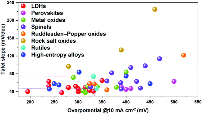 | ||
| Fig. 1 Comparison of the OER performance of classical electrode/catalyst materials. Benchmarks are IrO2 and RuO2; the different types of catalyst materials are categorized by using different colours. | ||
Initially, α-Ni(OH)2 was the first metal hydroxide identified to exhibit OER electrocatalytic activity,89 then it was further revealed that doping it with other metal cations with variable oxidation states can boost the OER activity of α-Ni(OH)2.90,91 Since then, transition metal (e.g., Co-, Ni-, Fe-, and Mn-) containing layered double hydroxides69,92,93 (LDHs) and their topotactic derivatives94,95 have been documented to exhibit outstanding performance towards the OER, originating from their highly controllable structure,96–98 intensive host–guest interactions99–101 and highly dispersed single-atomic sites.102
There are already several review articles which have summarized the development of LDHs for the OER from material and characterization perspectives. For example, exfoliating LDHs,62 doping LDHs103 and introducing defects84 into LDH nanosheets, as well as compositing LDHs with carbon nanotubes (CNTs),104 have been chosen as methods to improve the understanding of LDHs for the OER. However, there is a lack of an overall comprehension and recognition of OER kinetics on LDHs; in particular, there is a gap regarding design and optimization of LDHs based on their atomic structure characteristics and larger scale electrode assembly to promote mass transportation for further development towards applications in industrial water electrolysers.
In this review, identification of active sites, at the atomic level, of LDHs for the OER is introduced and discussed in detail, based on the OER mechanism in alkaline medium. The current strategies for active site optimization to enhance the OER performance of LDHs are summarised. Furthermore, the development of superaerophobic electrodes based on LDHs for a large-scale OER is explored. Finally, we offer perspectives into challenges faced by industrial-scale water splitting for hydrogen production, and point out the enormous potential of using LDHs in addressing these challenges.
2. Fundamental characteristics of LDHs
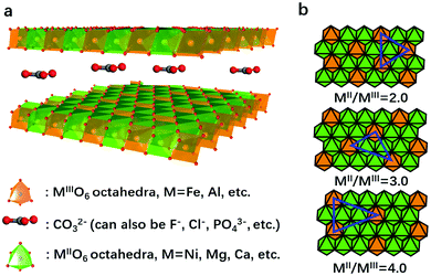
LDHs are a series of two-dimensional nanomaterials as shown in Fig. 2a, in which MO6 (where M stands for the metallic cation) octahedra constitute the nanosheets, and the intercalated anions are confined between the layers.105,106 A general formula unveiling the composition of LDHs is MII1−xMIIIx(OH)2(An−)x/n·yH2O,107 where MII and MIII are divalent and trivalent metallic cations, respectively, and An− is the intercalated anion (e.g., CO32−) neutralizing the positive charge of the nanosheets.108,109 A wide variety of divalent, trivalent, or even higher valence state cations can be selected to construct the nanosheets, while multiple anions can be intercalated between the layers, leading to the highly flexible and controllable composition and structure of LDHs.110The structure recognition of LDHs can be traced back to 2008. Nielsen et al.111 used 1H–27Al double-resonance and 25Mg triple-quantum MAS NMR to study the local configuration of Mg and Al in LDH nanosheets. The results showed that the cations were fully ordered for a Mg![[thin space (1/6-em)]](https://www.rsc.org/images/entities/char_2009.gif) :
:![[thin space (1/6-em)]](https://www.rsc.org/images/entities/char_2009.gif) Al ratio of 2
Al ratio of 2![[thin space (1/6-em)]](https://www.rsc.org/images/entities/char_2009.gif) :
:![[thin space (1/6-em)]](https://www.rsc.org/images/entities/char_2009.gif) 1, and at a lower aluminum content, a non-random distribution of cations persists with no Al3+–Al3+ close contacts. We thus propose to consider LDHs as “hydroxide solid solutions” with single-atomic dispersion of MIII (or MIV) in the matrix of MII(OH)2 nanosheets based on previous structure investigations.111,112 That is, the MII and MIII cations in the LDH nanosheets can replace each other as long as no M(III)–O–M(III) is formed. The MII/MIII cation ratio can be widely tuned without restructuring the layered structure. This is the feature of a solid solution that forms after the dissolve–precipitate ripening process, to arrive in a thermodynamically stable state. In the LDH nanosheets, MII (or MIV) cations can be regarded as the matrix (or solvents), while MIII can be considered as “solute” or dopant species to replace MII sites. Due to the high electrostatic force existing between high valence MIII (or MIV) cations in the LDH nanosheets, MIII (or MIV) cations could not bridge each other by sharing oxygen atoms (unless, in some cases, M(III)–O–M(III) forms due to insufficient crystallization or ripening), but only existed randomly and single-atomically in the nanosheets, regardless the MII/MIII ratios (Fig. 2b). However, to well isolate the MIII ions, much more MII ions are required, which makes the MII/MIII ratio larger than 2 in most cases. It has been observed that the MII/MIII ratio = 3
1, and at a lower aluminum content, a non-random distribution of cations persists with no Al3+–Al3+ close contacts. We thus propose to consider LDHs as “hydroxide solid solutions” with single-atomic dispersion of MIII (or MIV) in the matrix of MII(OH)2 nanosheets based on previous structure investigations.111,112 That is, the MII and MIII cations in the LDH nanosheets can replace each other as long as no M(III)–O–M(III) is formed. The MII/MIII cation ratio can be widely tuned without restructuring the layered structure. This is the feature of a solid solution that forms after the dissolve–precipitate ripening process, to arrive in a thermodynamically stable state. In the LDH nanosheets, MII (or MIV) cations can be regarded as the matrix (or solvents), while MIII can be considered as “solute” or dopant species to replace MII sites. Due to the high electrostatic force existing between high valence MIII (or MIV) cations in the LDH nanosheets, MIII (or MIV) cations could not bridge each other by sharing oxygen atoms (unless, in some cases, M(III)–O–M(III) forms due to insufficient crystallization or ripening), but only existed randomly and single-atomically in the nanosheets, regardless the MII/MIII ratios (Fig. 2b). However, to well isolate the MIII ions, much more MII ions are required, which makes the MII/MIII ratio larger than 2 in most cases. It has been observed that the MII/MIII ratio = 3![[thin space (1/6-em)]](https://www.rsc.org/images/entities/char_2009.gif) :
:![[thin space (1/6-em)]](https://www.rsc.org/images/entities/char_2009.gif) 1 results in slightly higher stability, according to repeated experiments. This unique structure provides opportunities for modulation of the MIII (or MIV) coordination environment and synergistic interaction between MIII (or MIV) and MII to enhance the electrocatalytic oxygen evolution activities of LDHs. Furthermore, two or even more species of high valent metallic cations can also be single atomically dispersed in the M2+–OHx matrix, due to the electrostatic repulsion, and synergic effects within the M3+/4+–O–M2+ couple can have a profound influence on the corresponding properties of LDHs.
1 results in slightly higher stability, according to repeated experiments. This unique structure provides opportunities for modulation of the MIII (or MIV) coordination environment and synergistic interaction between MIII (or MIV) and MII to enhance the electrocatalytic oxygen evolution activities of LDHs. Furthermore, two or even more species of high valent metallic cations can also be single atomically dispersed in the M2+–OHx matrix, due to the electrostatic repulsion, and synergic effects within the M3+/4+–O–M2+ couple can have a profound influence on the corresponding properties of LDHs.
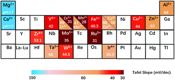
In Fig. 3a, we summarize the representative studies on preparing and applying LDHs for the OER.62,79–82,85,86,97,113–122 It can be clearly seen that NiFe-LDHs show a superior OER catalytic performance over other binary LDHs; therefore, NiFe-LDHs can be identified as the optimal framework for compositional modulation. In NiFe-LDHs, both metal elements are redox-active, and Ni2+ is used as a “solvent” to isolate Fe3+ ions. During the OER process, a pre-oxidation of metal ions to higher oxidation states can be observed. Fig. 3b shows the typical OER polarization curves of NiFe-LDHs in an alkaline medium. The oxidation and reduction of Ni2+/Ni3+ occur in the overpotential range of 0.1–0.2 V, while the OER overpotential is located after 0.2 V. As shown in the inset, two locations (edge or bulk) and two species (Ni or Fe) of metal sites in the LDHs are all potentially responsible for the OER activity. Therefore, the identification of OER active sites in LDHs is of significant importance for the design and preparation of the next generation of efficient OER catalysts based on LDHs.
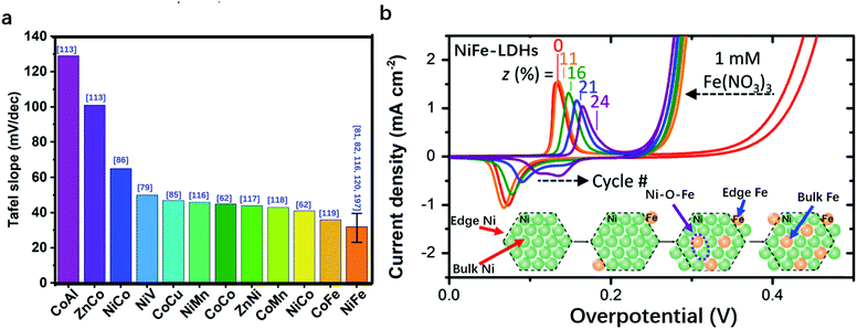 | ||
| Fig. 3 Comparison of the performance of various LDHs for the OER in terms of Tafel slope. (a) The bar charts show that OER on Fe-containing/NiFe-LDHs exhibits a smaller Tafel slope. The error bar corresponds to the different Tafel slopes of NiFe-LDHs reported in different studies. The blue numbers in the brackets in Fig. 3a correspond to the cited references. (b) Typical polarization curves of NiFe-LDHs for the OER and the corresponding distribution of metal sites in the LDHs. | ||
3. OER pathways and identification of active sites on LDHs for the OER in alkaline media
3.1 OER pathways on LDHs in alkaline media
LDHs as transition metal hydroxide materials will inevitably dissolve in acidic media. Therefore, the OER on LDHs has always been conducted under alkaline conditions, where the OER may occur via (a) an adsorbate evolution mechanism (AEM)123,124 or (b) a lattice oxygen oxidation mechanism as shown in Fig. 4.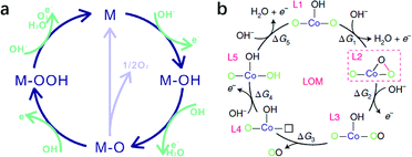 | ||
| Fig. 4 Proposed OER mechanism on LDHs in alkaline medium. (a) Adsorbate evolution mechanism (AEM). Reproduced with permission.123 Copyright 2019, The Royal Society of Chemistry. (b) Lattice oxygen oxidation mechanism (LOM). Reproduced with permission.125 Copyright 2019, the authors. | ||
The adsorbate evolution mechanism (AEM), a well-known mechanism that involves successive adsorption and desorption of oxygenated intermediates on the unsaturated coordinated metal ion (M*) as active sites, has already been verified by simulation and experiments.126 The process consists of the continuous adsorption of oxygenated intermediates (M* → M–OH; M–O → M–OOH), the deprotonation of hydrogen (M–OH → M–O), and the desorption of oxygen (M–O–OH → M*) on active sites, although some reports argue that two M–O species get combined and converted into O2 and M active sites at the surface. According to the scaling relationship (ΔGOOH − ΔGOH = 3.2 ± 0.2 eV) in the AEM, if ΔGO − ΔGOH > 1.6 ± 0.1 eV, then the formation of ΔGO would be the rate determining step with an overpotential of >0.38 V; by contrast, if ΔGOOH − ΔGO > 1.6 ± 0.1 eV, the formation of ΔGOOH would be the rate determining step with an overpotential of >0.37 V. Thus, according to the Sabatier principle, the optimal Gibbs free energy change for every single step in the OER is 1.6 ± 0.1 eV.
Consequently, the identification of active sites of LDH-based OER electrocatalysts, by spectroscopic study of the binding energy of active metallic sites to OER intermediates, is critical for further optimization or atomic structure design.
Besides the AEM mechanism, some recent findings propose that the lattice oxygen oxidation mechanism (LOM), which involves O–O coupling during the OER and is similar to some recently reported OER processes on perovskites, may also be possible for LDH catalysed OERs.125 However, only a few LDHs have been studied, and in most cases, Co was involved (e.g., Co–Zn oxyhydroxide),123 so the applicability of the LOM on other LDHs (e.g. NiFe-LDHs as we discussed in detail) for the OER needs further verification; therefore our discussion will be mainly based on the AEM.
3.2 Identification of the active sites on LDHs for the OER in alkaline media
Besides the revelation of the working pathway of LDHs in the OER, the identification of active sites in LDHs, by which we can rationally modulate the binding strength of intermediates to metal sites, is also indispensable for preparing efficient OER catalysts. Binary transition metal cations with high redox activity are always preferred for the OER,106,127 so the combinations of Ni2+/3+, Co2+/3+, Fe2+/3+ metal cations in LDH nanosheets are the most extensively researched objects among all the LDH species. Thus, identification of the active sites using experimental126,128 and computational tools has been carried out mostly on Ni-, Co- and Fe-containing LDHs. NiFe-LDHs show the highest activity among the binary LDHs and are substantially more cost-effective for future large-scale utilization. Despite the fact that only two metals exist in plane, the origin of the high OER activity is still ambiguous. The controversial assumption of active sites being Ni sites on the NiFe-LDHs started from the early 21st century and then turned to be Fe sites; while more recent studies, based on the full utilization of advanced research techniques available, have proposed that the synergy between Ni and Fe sites was responsible for OER activity.A pioneering study was reported by Bell's group as shown in Fig. 5a. They tracked the electrode surface transformation from Ni(OH)2 into NiOOH using in situ Raman spectra129 recorded at a potential of 0.47 V vs. Hg/HgO.130 The band in the range of 445–465 cm−1 in the lower potential region in Fig. 5a can be attributed to the Ni–O vibration of Ni(OH)2. Upon increasing the potential to 0.47 V and above, a new pair of bands appeared at 474 and 554 cm−1, respectively, which were attributed to Ni–O vibrations in NiOOH. This work suggested that the OER was catalysed by Ni3+ in NiOOH, leading to a significant enhancement in the potential at which the Ni(OH)2/NiOOH redox reaction occurred. Also, XAS was applied by Nocera et al. to identify the OER active sites on NiFe-LDHs.131 The authors identified Ni4+ ions as the active sites, while the Lewis acid Fe3+ in NiFe-LDHs served to increase the acidity of OHx (aqua/hydroxo) moieties that are coordinated to nickel, thereby lowering the reduction potential for the Ni4+/3+ redox couple and thus generating a greater population of Ni4+ in the Fe-doped catalysts, and, correspondingly, benefited the enhancement of OER activity. In situ X-ray absorption spectroscopy (XAS), which is capable of revealing the valence state and coordination environment132–134 of active sites on LDHs during the OER process, was also employed to provide direct information on the evolution of both the electronic and atomic structures of LDHs.135,136 The work by Bell and Friebel as shown in Fig. 5b and c unveiled that the Fe–O bond length contracted from 2.01 Å at 1.12 V to 1.90 Å at 1.92 V, indicating that the Fe hydroxides were actively transformed during the OER and the interaction between Fe and lattice oxygen at the OER potential was noticeably stronger than that of Ni.137 The phase evolution differences between Ni–OH and Fe–OH may indicate that Fe played a more significant role in NiFe-LDHs for the OER. Cai et al. reported the synthesis of Fe2+ doped NiFe-LDHs (NiFe2+Fe3+-LDHs) and presented the structural evolution during the OER by employing in situ XANES, which can identify both Fe2+ and Fe3+.82 As shown in Fig. 5d, the Fe species in the NiFe2+Fe3+-LDHs without applied potential showed mixed valence states of both +2 and +3. The valence state increased to +3.22 at 1.5 V with a shortened Fe–O bond (partial Fe4+ among all Fe species), and remained in the +3.22 state for a short period of time even when the potential was set at 0 V. These studies have expanded further on previous findings and pointed out that Fe was the active site in LDHs for the OER with the support of in situ XAS data.
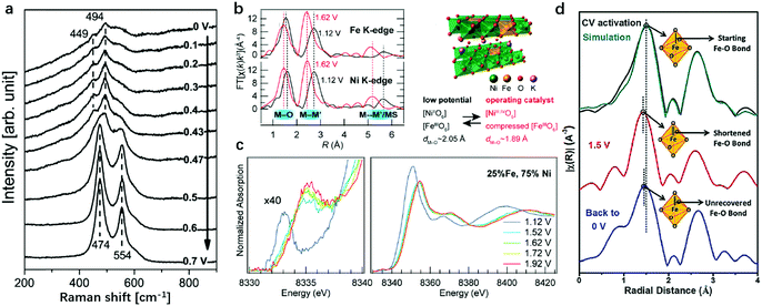 | ||
| Fig. 5 Identification of the active sites for the OER on Ni oxide and NiFe-LDHs in alkaline medium using in situ Raman spectra and XAS. (a) In situ Raman spectra collected from the Ni oxide electrode, as a function of potential in 0.1 M KOH at potentials of 0 V to 0.7 V vs. Hg/HgO (1 M KOH). Reproduced with permission.130 Copyright 2013, The American Chemical Society. (b) and (c) Complementary operando EXAFS measurements confirmed the potential-induced bond contraction at both Fe and Ni sites. The structure model of Fe doped γ-NiOOH. Ni K-edge XAS shows shifts in both oxidation state-sensitive and structure-sensitive features due to the oxidation of Ni2+ sites. Reproduced with permission.137 Copyright 2015, The American Chemical Society. (d) The k2-weighted Fourier transformed in situ EXAFS data of Fe2+-NiFe-LDHs under OER working conditions, demonstrating the Fe–O bond-length variation. Reproduced with permission.82 Copyright 2018, Wiley-VCH. | ||
To elucidate the role and evolution of Fe cations in hydroxides during the whole process of the OER, Jin et al. developed operando Mössbauer spectroscopy to probe the valence states of Fe cations in NiFe-LDHs during the OER process.138Fig. 6a shows the CV curve collected prior to Mössbauer spectral measurement. The Mössbauer spectra were recorded initially at the open circuit potential, then at various potentials of 1.49 V, 1.62 V and 1.76 V, and finally returned to the open circuit potential. Under open circuit conditions, a doublet with an isomer shift of 0.34 mm s−1 and a quadrupole splitting of 0.46 mm s−1 were observed for the NiFe-LDHs, which remained relatively stable until 1.49 V. With increasing working potential, a shoulder appeared at −0.27 mm s−1, and the intensity reflected the oxidation of approximately 12% (at 1.62 V) and 21% (at 1.76 V) of Fe species in LDHs, which corresponded to the assignment of localized species as Fe4+. When the potential returned to 1.49 V or to the open circuit potential for a short period of time, Fe4+ was still detected. This work provided clear evidence for the formation of Fe4+ in NiFe-LDHs during the OER, and the role of Fe species in catalysing oxygen evolution began to be recognized.
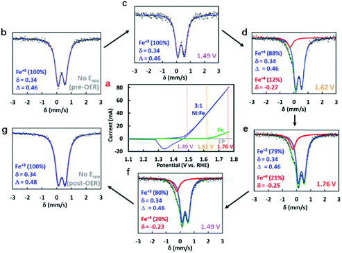 | ||
| Fig. 6 Identification of Fe4+ in NiFe-LDHs during the OER using Mössbauer spectra. (a) Cyclic voltammograms of NiFe layered oxyhydroxide (blue) and hydrous Fe oxide (green) electrocatalysts employed in the operando experiments with Mössbauer spectra collected at the open circuit potential (grey), 1.49 V (purple), 1.62 V (yellow), and 1.76 V (red). (b–g) Mössbauer spectra at different applied potentials. Reproduced with permission.138 Copyright 2015, The American Chemical society. | ||
Since both Ni and Fe cations are redox active sites on LDH nanosheets, the precise roles of Ni and Fe in the OER activity of LDHs need to be clarified. Friebel et al. constructed several models to identify the role of Fe in Fe doped NiOOH for the OER as shown in Fig. 7. It was shown that subsurface Fe sites in γ-NiOOH increased the OER overpotential at surface Ni sites (0.56 V to 0.59 V)137 by weakening the binding strength of oxygenated intermediates to the Ni site (the Fe doping results in the anodic shift of the Ni2+ oxidation peak prior to the OER onset). However, the surface Fe exhibited a lowered overpotential for the OER (η = 0.43 V), which was close to the experimental result (nearly 0.3 V), indicating that Fe rather than Ni has a higher OER activity. Although a growing number of published studies claim that Fe has a higher OER activity than Ni, Fe-doped NiOOH with high Fe content (55 at% Fe)126 fails to show attractive OER electrocatalytic activity, and the overpotential for the OER on a single Fe site revealed by density functional theory (DFT) calculations is considerably higher than that presented by the polarization curve obtained experimentally. This implies that not all the Fe atoms, but only the Fe atoms chemically surrounded by Ni atoms are potentially OER active. Thus, a synergistic interaction between Ni and Fe in NiFe-LDHs has been recognised and has attracted increasing attention.
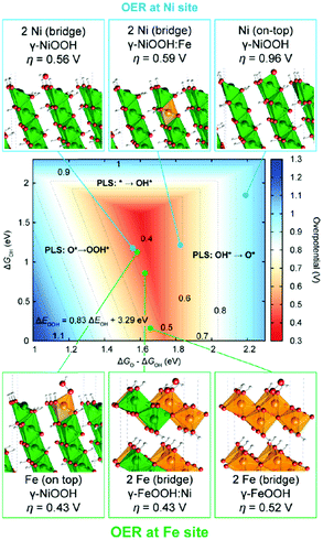 | ||
| Fig. 7 Identification of the active sites for the OER on metal hydroxides by theoretical methods. Theoretical OER overpotentials at Ni and Fe surface sites in pure and doped γ-NiOOH and γ-FeOOH model structures. Reproduced with permission.137 Copyright 2015, The American Chemical Society. | ||
Goddard III and Xiao used grand canonical quantum mechanics and DFT with exact atomic exchange to check the OER activity of γ-(Ni,Fe)OOH: the OER overpotential decreased from 1.22 V on pure γ-NiOOH to 0.83 V on the 1/3 surface Fe doped γ-(Ni,Fe)OOH and 0.42 V on the 1/3 surface plus 1/3 subsurface Fe doped γ-(Ni,Fe)OOH (Fig. 8a).139 The substitution of Ni by Fe had an obvious impact on the reactivity for the OER. As shown in Fig. 8a, the free energy required for O radical formation was reduced from 2.04 eV to only 1.20 eV (as compared with pristine NiOOH), while the barrier for O–O coupling increased slightly to 0.60 eV. The combination of O radicals with O–O coupling led to an overpotential of 0.42 V, which was very close to the experimental value (0.3–0.4 V). The authors unveiled that the high spin d4 Fe(IV) led to the efficient formation of the O radical intermediate (M–O), while the closed shell d6 Ni(IV) catalysed the subsequent O–O coupling; thus, it was the synergy between Fe and Ni rather than any single active site that delivered the optimal performance for the OER. This work provided insights into the OER activity on NiFe-LDHs from the computational viewpoint, and for the first time, both Ni and Fe were suggested to play an important role synergistically in influencing the OER activity of NiFe-LDHs.
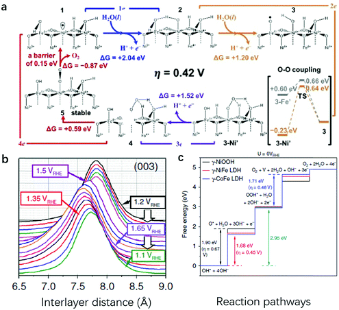 | ||
| Fig. 8 Synergy between Ni and Fe sites identified on NiFe-LDHs during the OER. (a) The mechanistic cycles for the OER on one-third surface Fe doped plus one-third subsurface Fe doped γ-(Ni,Fe)OOH catalysts. The free energy input required for O radical formation is reduced drastically to 1.2 eV, while the barrier for O–O coupling increases slightly to 0.6 eV. This combination leads to an overpotential@10 mA cm−2 of 0.42 V. Reproduced with permission.139 Copyright 2018, the authors. (b) Waterfall plots of normalized and background-subtracted (003) peaks obtained during in situ WAXS and potential steps for NiFe-LDHs in 0.1 M KOH. (c) Reaction free-energy diagrams for the OER on γ-NiOOH, γ-NiFe LDHs, and γ-CoFe LDHs; the potential limiting steps and the OER overpotentials are also given. Reproduced with permission.140 Copyright 2020, the authors. | ||
Recently, Strasser et al. combined operando wide-angle X-ray scattering (WAXS) and absorption spectroscopy, differential electrochemical mass spectrometry (DEMS), and DFT calculations to elucidate the catalytically active phase, reaction centre and OER mechanism.140 From the perspective of crystallinity, their data showed that Fe-containing bimetallic LDHs were oxidized from the as-prepared α-phases to activated γ-phases with around 8% lattice spacing contraction (Fig. 8b). From the active site identification perspective, their data revealed that the OER progressed via a Mars–van Krevelen mechanism,139 where the synergy between surface Fe sites and the nearest-neighbour M sites worked through the formation of O-bridged Fe–M reaction centres, stabilizing OER intermediates and fundamentally accounting for the high catalytic activity of MFe LDHs (Fig. 8c). In a recently published study, Wang et al. applied DFT calculation first and then used an acid-etching experimental method to verify that the edge Fe sites showed superior OER activity in the presence of Ni atoms; while Fe–O–Fe in Fe(OH)3, bulk metal sites and Ni sites were less active.141 These findings are in line with the calculation work by Goddard III and Xiao,139 where a conclusion was reached that Ni–O–Fe jointly functioned as the active centre on NiFe-LDHs.
To further probe and compare the exact contributions from Ni, Fe and even lattice oxygen in NiFe-LDHs for OER activity, Hu et al. studied different reaction sites on the LDHs, using 18O-labeling experiments in combination with in situ Raman spectroscopy to probe whether lattice oxygen was involved during the OER (Fig. 9a and b).142 In pure Ni-LDHs, the Raman peak changed from Ni–18O to Ni–16O as the OER proceeded, illustrating that the lattice oxygen in Ni-LDHs was actively involved in the OER. However, the NiFe-LDHs showed steady δ(NiIII–O), ν(NiIII–O) and ν(O–O) peaks in the Raman spectra regardless of the change of electrolyte (whether labelled with 18O or 16O). In other words, O2 evolved through an active oxygen species (Ni–O–O˙) on the Ni sites and with lattice oxygen participation; whereas on Fe sites, O2 evolved neither with lattice oxygen participation, nor through an active oxygen species. When the OER occurs through Ni sites, the lattice O should exchange with the O atoms of the OH− electrolyte (Fig. 9c). On the other hand, when the OER occurs through Fe sites, there is no exchange of lattice O with OH−, suggesting that only the Fe sites were OER active in NiFe-LDHs142,143 (Fig. 9d). Hu et al. also used the procedure to study the OER activity on individual Ni or Fe in NiFe-LDHs by comparing the degree of O exchange on them during the OER.144 The turnover frequency (TOF) on Fe was found to be 20–200 times higher than that on Ni when the Fe content accounted for 4.7%.
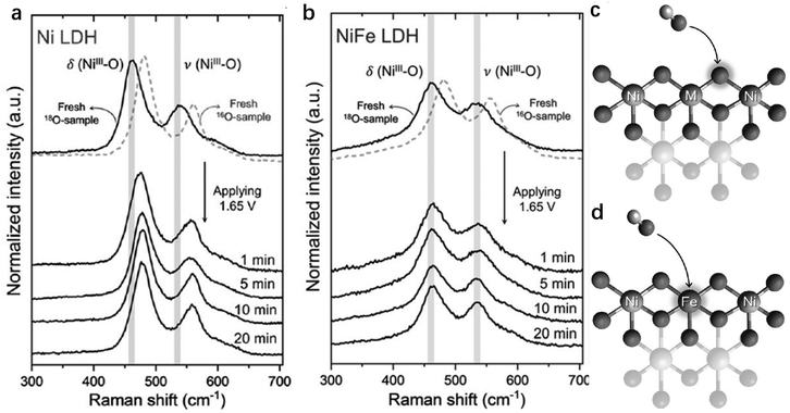 | ||
| Fig. 9 Identification of the active sites by isotope labelling experiments. (a and b) In situ Raman spectra of 18O labelled Ni-LDHs (a) and NiFe-LDHs (b) recorded at 1.65 V in 0.1 M KOH in H216O. The models illustrating the different roles of lattice oxygen in OER catalysis: (c) participation of lattice oxygen in NiNi- and NiCo-LDHs; and (d) nonparticipation of lattice oxygen in NiFe-LDHs. M = Ni or Co. Reproduced with permission.142 Copyright 2019, Wiley-VCH. | ||
This indicated that Fe was considerably more active than Ni on the NiFe-LDHs for the OER. The experimental data were in line with computational results, and suggested that Fe sites had superior OER activity to Ni sites.
4. Strategies to enhance the OER on LDHs by tailoring active sites on an atomic scale
The abovementioned experimental and computational studies focused on identifying the active sites at the atomic level and shedding light on the future design of efficient OER catalysts. Since Ni and Fe are both indispensable sites accounted for the boosted OER performance, the modulations of the Ni–O–Fe motif with an optimized electronic structure are one of the key goals for active site tailoring. Some strategies have been attempted to enhance the OER performance of NiFe-LDHs. These include the following 4 aspects: (1) compositional optimization, i.e., substituting Ni2+ with other M2+ to modulate the electronic structure of Fe2+, or replacing Fe3+ with other M3+ to optimize the electronic structure of Ni2+; (2) coordination environment modulation, i.e., from making metal vacancies to tailoring the number of edge sites, and introducing oxygen vacancies to generate more unsaturated metal sites; (3) host–guest interaction, i.e., intercalating different anions to tailor the basal spacing or induce electron transfer between metal sites in nanosheets and intercalated species; and (4) noble metal loading, i.e., adding noble metal cations as both active sites and electronic structure mediators to metal sites in nanosheets.4.1 Modulation of the compositions of LDH nanosheets
Modulation of the compositions of LDH nanosheets can be achieved in large varieties, e.g., M2+ in the nanosheets can be selected from Mn2+, Co2+, Fe2+, Mg2+, etc., and M3+ in the nanosheets can be selected from Fe3+, Co3+, Cr3+, V3+, etc.145,146 Taking NiFe-LDHs as the benchmark for the OER, and the Ni–O–Fe motif serving as the active centre, there are several representative studies that involve doping with a third metal cation. Heterovalent metal cations in LDH nanosheets have previously been achieved and resulted in a further improvement in OER activity.According to the AEM mechanism (Fig. 4a), metal sites with an electron-rich structure can be easily oxidized, which are highly active towards the OER. Cai et al. constructed Fe2+–O–Fe3+ motifs as the active sites, showing simultaneously high stability and high activity for the OER as shown in Fig. 10a.82 Doping with Fe2+ first modified the electronic structure of Ni and Fe, resulting in an electron-rich structure at all metal sites available on NiFe-LDHs; at the same time, the specially designed Fe2+–O–Fe3+ significantly increased the adsorption of OER intermediates on NiFe2+Fe3+-LDHs. The latter can be confirmed by the cathodic shift of the Ni2+/Ni3+ redox potential and the boosted OER performance with a smaller overpotential of 249 mV at 10 mA cm−2 (Fig. 10b). However, excessive Fe2+ doping weakens the interaction between Ni and Fe, resulting in the OER onset potential on Fe2+–NiFe-LDHs being shifted anodically. In another case, Co2+ and Co3+ were doped into NiFe-LDH nanosheets to substitute Ni2+ and Fe3+, respectively, as shown in Fig. 10c;147 the Volcano plot correlated the overpotential with ΔE*O, and the effect of Co doping on the OER activity of NiFe-LDHs was summarised, specifically, from the viewpoints of the M2+/M3+ ratio and doping Co cation valence state. The results shown in Fig. 10d showed that at a fixed M2+/M3+ ratio, the replacement of Fe3+ with Co3+ had a more positive effect on the overall OER activity. The Co3+ modified the electronic structure of the Ni site (enlarged Ni2+ oxidation peak in the blue curve) and benefited the electron transfer in NiCo3+Fe-LDHs.
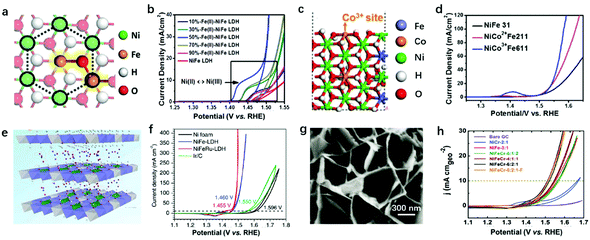 | ||
| Fig. 10 Modulation of the compositions of LDH nanosheets for improving OER activity. (a) A schematic atomic arrangement of NiFe2+Fe3+-LDHs. (b) CV curves of NiFe2+Fe3+-LDHs with different Fe2+/Fe3+ ratios. Reproduced with permission.82 Copyright 2018, the authors. (c) Schematic atomic arrangement of Co3+-doped NiFe-LDHs. (d) Linear sweep voltammetry polarization curves of the as-prepared NiCo2+Fe211, NiCo3+Fe611, and NiFe31-LDH. Reproduced with permission.147 Copyright 2018, Elsevier Ltd. (e) Scheme of Ru3+ doped NiFe-LDHs. (f) Polarization curves of the NiFeRu-LDHs, NiFe-LDHs, nickel foam, and Ir/C electrocatalysts. Reproduced with permission.148 Copyright 2018, Wiley-VCH. (g) SEM image of NiFeCr-LDHs. (h) OER polarization curves for various LDH samples deposited on GC electrodes at a constant loading of 0.2 mg cm−2. Reproduced with permission.149 Copyright 2018, Wiley-VCH. | ||
Li et al. reported doping V into NiFe-LDHs for enhanced OER activity.150 XPS spectra revealed that the binding energy of Fe 2p3/2 shifted negatively from 713.1 to 712.4 eV after V doping, indicating the charge compensation between metal cations induced by differences in electronegativity (EN). V3+ had a lower EN than Fe3+ and tended to donate electrons to the surrounding Fe3+, resulting in the oxidation of V3+ to V4+ and V5+, accompanied by the reduction of Fe3+. The corresponding NiFeV-LDHs exhibited enhanced OER activity over NiFe-LDHs and RuO2, and it only required a small overpotential of 195 mV to reach an OER current density of 20 mA cm−2. On top of the active site modulation, the high valence states of V4+ and V5+ also benefited the electron transport in NiFeV-LDHs; for example, the resistivity decreased from (2.4 ± 0.3) × 103 Ω sq−1 (NiFe-LDHs) to (1.3 ± 0.2) × 103 Ω sq−1 (NiFeV-LDHs) by changing the conducting band state of the LDHs, which is in accordance with the results of Co3+ doped materials.151 Similar activity enhancement was observed on NiV-LDHs,79 in which V played key roles in modulating the electronic structure of metal sites and contributed collectively to the enhanced OER performance.152 Relying on single atomic dispersion of Fe3+ and the function-oriented replacement of high valence state metal ions in LDH nanosheets, a strategy for accelerating the oxygen evolution kinetics of the NiFe-LDHs by partially substituting Fe3+ ions with Ru3+ was proposed by Feng et al. (Fig. 10e).148 The NiFeRu-LDHs showed an exceptionally low overpotential of 225 mV for the OER at 10 mA cm−2 as depicted in Fig. 10f.
In 2017, Jin et al. prepared Cr-doped NiFe-LDHs for catalysing the OER (Fig. 10g).149 The XPS binding peak corresponded to Fe2+ that emerged with Cr3+ doping, proving that the interaction between Cr3+ and Fe3+ led to the electronic structure change from electron-equilibrium to electron-rich, which can also be described as the Fe3+ sites being partially reduced. This tuned electronic structure led to the improved OER activity of NiFeCr-6![[thin space (1/6-em)]](https://www.rsc.org/images/entities/char_2009.gif) :
:![[thin space (1/6-em)]](https://www.rsc.org/images/entities/char_2009.gif) 2
2![[thin space (1/6-em)]](https://www.rsc.org/images/entities/char_2009.gif) :
:![[thin space (1/6-em)]](https://www.rsc.org/images/entities/char_2009.gif) 1-LDHs as confirmed in Fig. 10h, where the onset potential shifted much earlier for the OER on NiFeCr-6
1-LDHs as confirmed in Fig. 10h, where the onset potential shifted much earlier for the OER on NiFeCr-6![[thin space (1/6-em)]](https://www.rsc.org/images/entities/char_2009.gif) :
:![[thin space (1/6-em)]](https://www.rsc.org/images/entities/char_2009.gif) 2
2![[thin space (1/6-em)]](https://www.rsc.org/images/entities/char_2009.gif) :
:![[thin space (1/6-em)]](https://www.rsc.org/images/entities/char_2009.gif) 1-LDHs. Furthermore, the synergy between NiFe-LDHs and substrates can also lead to electronic structure modulation of both Ni and Fe sites. Recently, Hu et al. decorated Co3O4 with NiFe-LDHs and correlated the electronic states of LDHs to the OER activity.153 After the decoration of Co3O4, the XPS binding energy of Ni and Fe shifted negatively compared with pristine NiFe-LDHs. Similarly, Co3O4@NiFe LDHs with electron-rich Ni and Fe showed superior OER activity over pristine NiFe-LDHs. This work may also provide guidance for the further design of improved LDHs for catalysing oxygen evolution.
1-LDHs. Furthermore, the synergy between NiFe-LDHs and substrates can also lead to electronic structure modulation of both Ni and Fe sites. Recently, Hu et al. decorated Co3O4 with NiFe-LDHs and correlated the electronic states of LDHs to the OER activity.153 After the decoration of Co3O4, the XPS binding energy of Ni and Fe shifted negatively compared with pristine NiFe-LDHs. Similarly, Co3O4@NiFe LDHs with electron-rich Ni and Fe showed superior OER activity over pristine NiFe-LDHs. This work may also provide guidance for the further design of improved LDHs for catalysing oxygen evolution.
Fig. 11 shows the modulation of the compositions of NiFe-based LDH nanosheets, in which most of the reductive metal cations, such as Fe2+, Mn2+, Cr3+ and V3+, can largely improve the OER activity of NiFe-LDHs by donating electrons to the parental Ni2+ and Fe3+. Specifically, the electronic structure of Ni2+ and Fe3+ will evolve from electron-equilibrium to electron-rich, benefiting the de-protonation step in the OER by enhancing the binding strength between the adsorbates and the active sites. Notably, recent research has reported that Mo5+ and W6+ can also improve the OER activity of NiFe-LDHs by lowering the valence state of Ni and Fe prior to the OER.154 On the other hand, redox inert homovalent metal cations such as Mg2+ and Ca2+ can reduce the intrinsic OER activity of NiFe-LDHs due to the decreased number of available active sites, although some recent reports show that doping Mg2+ and Ca2+ into NiFe-LDHs can improve the OER activity in neutral medium by enhancing the water dissociation process.
Doping Cu2+ into NiFe-LDH nanosheets can induce structural disorder due to the Jahn–Teller effect, which can modulate the OER activity from a crystallinity perspective (the amorphous structure can lead to more exposed uncoordinated sites). Doping with Zn2+ and Al3+ hardly benefits the electronic structure of active sites but reduces the number of active sites, which may be comparable to that of Ca2+ and Mg2+; however, the solubility of Zn2+ and Al3+ in alkaline medium may also influence the OER performance of NiFe-LDHs by tailoring the coordination environment of the metal sites. From the above findings, a bold perspective can be put forward for discussion: as long as the radius of doping metal cations fits in the LDH matrix, the modulation of the compositions of LDH nanosheets for enhancing their OER activity can always be explored. The factors to consider are: the selection of doping cations, location and arrangement of doping cations in the nanosheets, whether the doping cations work alone or as an integration to affect the OER performance, etc.
4.2 Modulation of the coordination environment of metal sites in LDH nanosheets
Two types of coordination environment modulation in LDH nanosheets are commonly used. The first one is the introduction of oxygen or metal vacancies into LDH nanosheets, and the second one is the exfoliation of LDH nanosheets into mono/few layers. In the process of vacancy introduction, approaches include plasma treatment, reducing flame treatment, hydrothermal treatment with the use of reducing reactants and acidic/alkaline etching.Wang's group reported a series of impressing and advancing vacancy engineering studies to enhance the OER activity of LDHs. As shown in Fig. 12a, the authors prepared CoFe-LDHs by a hydrothermal method and then subjected the intact CoFe-LDHs to a dielectric barrier discharge (DBD) plasma reactor for 5 min to obtain vacancy-rich CoFe-LDH nanosheets.119 The OER on the water-plasma exfoliated CoFe-LDH nanosheets required a low overpotential of 290 mV to reach a current density of 10 mA cm−2, while the pristine CoFe-LDHs needed an overpotential of 332 mV, highlighting the promoting role of vacancies in enhancing the OER performance of LDHs.
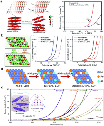 | ||
| Fig. 12 Modulation of the coordination environment of metal sites in LDH nanosheets for improving OER activity. (a) A schematic illustration of the water-plasma-enabled exfoliation of CoFe-LDH nanosheets and the corresponding OER performance. Reproduced with permission.119 Copyright 2017, Wiley-VCH Verlag GmbH & Co. KGaA, Weinheim. (b) Schematic illustration of selective defect engineering of NiFe-LDHs. Polarization curves of Zn2+ doped NiFe-LDHs and Al3+ doped NiFe-LDHs before and after alkaline etching. Reproduced with permission.155 Copyright 2018, Tsinghua University Press and Springer-Verlag GmbH Germany, part of Springer Nature. (c) A schematic illustration of the preparation of Ni3FeAlx–LDH nanosheets. Reproduced with permission.156 Copyright 2017 Elsevier Ltd. (d) OER polarization curves of LDHs prior to and after exfoliation in 1 M KOH. Reproduced with permission.62 Copyright 2014 Macmillan Publishers Limited. | ||
In addition to oxygen vacancies, introduction of metal vacancies via alkaline etching could selectively create M2+ or M3+ vacancies in LDH nanosheets. In a recent study, Sun et al. proposed a strategy that uses doping and then etching to selectively construct M2+ or M3+ defects into NiFe-LDH nanosheets. As shown in Fig. 12b, the authors deliberately introduced base-soluble Zn2+ and Al3+ cations into NiFe-LDHs, in which the Zn2+ substituted Ni2+ in the nanosheets and the subsequent etching of Zn2+ created M2+ defects and left nearby unsaturated Fe3+ exposed. In contrast, doping Al3+ would substitute Fe3+ in the nanosheets and the subsequent etching of Al3+ created M3+ defects and left nearby unsaturated Ni2+ exposed.155 The results illustrated that the doping with Zn2+ and Al3+ in NiFe-LDHs both had a negative effect on the OER activity of NiFe-LDHs. However, the enhanced OER activities of NiFe-LDHs were observed after the etching process. Also shown in Fig. 12b, to reach the same current density, the applied potentials on D-NiFeZn and D-NiFeAl-LDHs were 80 and 48 mV lower, respectively, than those of pristine NiFeZn and NiFeAl LDHs, with that of D-NiFeZn-LDHs even surpassing that of pristine NiFe-LDHs. The electronic structure evolution for both Ni and Fe from an electron-equilibrium to electron-rich state was responsible for the improved OER activity. In the same year, Jin et al. introduced Al3+ into NiFe-LDHs (Fig. 12c);156 they found that etching of Al3+ species in strong alkaline solution during an OER test would greatly benefit the formation of Ni3+ species as active sites. Despite the Al3+ and Fe3+ being bridged by O in the precursor, the above process was possibly because of the fast nucleation. The prepared Ni3FeAlx-LDHs exhibited high activity and favourable kinetics. The etching of Al3+ tailored the coordination environment of Ni2+ as evidenced by the earlier transformation from Ni(OH)2 into NiOOH in the forward CV scan. The defect rich LDHs not only improved the intrinsic activity but also increased the electrochemical surface area of Ni3FeAlx-LDHs.
The exfoliation of LDH nanosheets into a monolayer (few layers) serves as another approach to tailor the coordination environment of the metal sites in LDHs. The strong electrostatic interaction between LDH nanosheets leads to ordered stacking along the (001) direction;157,158 hence the majority of active sites are inhibited by hydroxyl groups and intercalated anions, resulting in a weakened exposure of active sites in LDHs. Previous studies showed that low-coordinated metal sites in disordered or amorphous structures can serve as the active sites for the OER;159–161 therefore, it is promising to further improve the OER activity of LDHs by increasing the proportion of low-coordinated active sites and manipulating the electronic structure of the metallic sites.162 Hence, a large amount of work has focused on the modulation of the active sites via exfoliation/delamination of LDH nanosheets.163–165 Hu et al. prepared a single layer/few layers of LDHs through an anion exchange-exfoliation method. Firstly, Br− intercalated CoCo-/NiCo-LDHs and Cl− intercalated NiFe-LDHs were prepared.62 Later on, the anion exchange was applied for the substitution of Br− with NO3− in CoCo-/NiCo-LDHs, and Cl− with ClO4− in NiFe-LDHs. The anion exchanged LDHs were then dispersed in degassed formamide to be exfoliated into a single layer or few layers. Fig. 12d shows the exfoliation process of LDH nanosheets and the OER performance of different LDHs before and after exfoliation. Obviously, a significant decrease in the overpotential can be observed after exfoliation. The authors further prepared ultrathin CoMn-LDHs by a one pot co-precipitation method; the Co(IV) species in the ultrathin and amorphous LDH layer contributed to the boosted OER activity, with a low overpotential of 324 mV at 10 mA cm−2, a small Tafel slope of 43 mV dec−1 and 2.8 times higher current density at an overpotential of 350 mV as compared with benchmark IrO2.118 Jin et al. also exfoliated NiCo-LDHs with formamide in a N2 atmosphere.166 The exfoliation procedure resulted in more metal sites with dangling bonds exposed and electron-rich structures of active sites, which benefited the adsorption of oxygenated intermediates, leading to the overall enhanced OER activity of LDH nanosheets.
4.3 Decoration of noble metal atoms into LDH nanosheets
The single atomic dispersion of redox active elements in LDHs makes the nanosheet structure an ideal substrate for loading noble metal atoms that also exhibit atomic dispersion. On one hand, noble metal atoms can act as mediators to tailor the electronic structure of transition metal sites in LDHs to further enhance the OER activity; on the other hand, the noble metal–oxygen–metal motif in LDHs enables noble metal atoms to act as the active sites for the OER.Zhang et al. first prepared Au decorated NiFe-LDHs by an electrodeposition method, and took advantage of single-atom Au decoration to facilitate the in situ generation of OER active NiFe oxyhydroxide from LDHs.167 The electronic interaction between Fe and the anchored Au (Fig. 13a) yielded a net Au-to-LDH charge redistribution, which facilitated the adsorption of OH− and modified the adsorption energy of O* and OOH* intermediates on Fe sites, resulting in a low overpotential required in the rate-limiting step. Ir species can be seen as the benchmark for OER catalysts and have also been used to decorate the surfaces of metal hydroxides as shown in Fig. 13b. Co and Ir precursors were mixed under vigorous stirring to prepare 3D CoIr hierarchical structure samples by Song et al. in 2018.168 The optimized CoIr with 9.7 wt% Ir content displayed an efficient OER performance with an overpotential of 373 mV to achieve a current density of 10 mA cm−2 in 1.0 M phosphate buffer solution and an overpotential of 235 mV at a current density of 10 mA cm−2 in 1.0 M KOH, outperforming commercial IrO2 catalysts. The interaction between Ir and Co(OH)2 facilitates the oxidation of Co(OH)2 to CoOOH and at the same time maintains the unsaturated coordination of Co atoms.
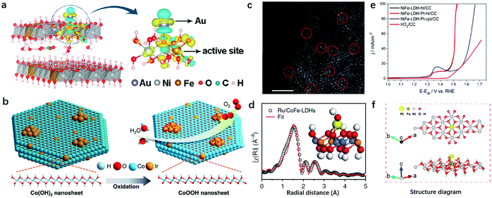 | ||
| Fig. 13 Decoration of noble metal atoms into LDH nanosheets for improving OER activity. (a) Differential charge densities of NiFe-LDHs with and without Au atoms, while one O atom adsorbed onto the Fe site. The iso-surface value is 0.004 e Å−3. Yellow and blue contours represent electron accumulation and depletion, respectively. Reproduced with permission.167 Copyright 2018, The American Chemical Society. (b) The mechanistic diagram of the OER on the CoIr-0.2 sample surface and the transformation of the α-Co(OH)2 into β-CoOOH phase. Reproduced with permission.168 Copyright 2018, Wiley-VCH Verlag GmbH & Co. KGaA, Weinheim. (c) The AC-STEM image of Ru/CoFe-LDH nanosheets shows the monoatomic ruthenium dispersed on the surfaces of the LDHs (some of the isolated Ru atoms are marked with red circles). Scale bar, 2 nm. Reproduced with permission.165 Copyright 2018, Springer Nature. (d) Model-based fittings of Ru EXAFS for Ru/CoFe-LDHs and simulated EXAFS spectra from Ru–O and Ru–O–M (M = Co or Fe) bonds (the inset shows the magnified local structure of Ru/CoFe-LDHs), showing the exclusive existence of Ru–O–M bonds in the Ru/CoFe-LDH sample. Reproduced with permission.169 Copyright 2019, The Springer Nature. (e) Polarization curves showing the OER on NiFe LDH crystalline sheets, Pt NP tethered NiFe LDH crystalline sheets, Pt NP tethered co-precipitated NiFe LDHs and IrO2 modified CC interfaces. Reproduced with permission.170 Copyright 2017, Elsevier Ltd. (f) Atomic structure of the Pt atom bonding to the ferric site in NiFe-LDHs. Reproduced with permission.171 Copyright 2018, the authors. | ||
Other than electronic structure modulation, noble metal atoms can also serve as active sites in LDHs. Li et al. prepared Ru anchored CoFe-LDHs via a mechanical stirring procedure.169 The spherical aberration corrected scanning transmission electron microscope (AC-STEM) (Fig. 13c) showed clearly that single-atomically dispersed Ru existed on the surfaces of the CoFe-LDHs. The elaborated structural characterization by EXAFS revealed that only the first-shell Ru–O bond and some weak Ru–O–M (M = Co or Fe) can be identified, while the Ru–Cl bond, metallic Ru–Ru bond and Ru–O–Ru bond from clustered ruthenium oxides cannot be identified, confirming the single-atom dispersion of Ru on the CoFe-LDHs (Fig. 13d). The host–guest interaction between the CoFe-LDH substrate and monatomic Ru improved the intrinsic activity of Ru, and facilitated the oxidation of Co and Fe, resulting in the high OER activity of the Ru/CoFe-LDHs with as low as 198 mV overpotential needed to drive a current density of 10 mA cm−2 in alkaline medium. Furthermore, the interaction between Ru and Co enhanced the stability of Ru against dissolution in a high valence state compared to commercial RuO2 catalysts. It is noted that the loading of single atomic noble metals onto LDHs should be performed under relatively mild conditions. For instance, Au was loaded onto NiFe-LDHs by electrodeposition for only a short period of time, and Ru was loaded onto CoFe LDHs by diluted KOH induced precipitation. In some other cases, when chloroplatinic acid and borohydride solution were mixed to anchor Pt onto NiFe-LDHs, the fast formation of Pt metal would induce quick nucleation and growth into nanoparticles as reported by Kundu170 as shown in Fig. 13e.
A study by Liang and Liu provided additional guidance from the computational perspective on the bonding sites to immobilize noble metal atoms.171 A model consisting of Pt and NiFe-LDHs, as shown in Fig. 13f, was constructed to elucidate the trend of the Pt atom being anchored on LDH nanosheets. The adsorption energy Ead of the Pt atom on the NiFe-LDH nanosheets (via the Fe3+–O(H)–Pt bonding) was −2.87 eV, which was stronger than that of the Pt atom adsorbed onto Ni(OH)2 nanosheets (via the Ni2+–O(H)–Pt bonding, −2.08 eV). The theoretical calculation revealed that Pt tended to bond with Fe3+; therefore, the interaction between Fe3+ and Pt was responsible for the site-specific loading and enhanced electrocatalytic activity of Pt–NiFe-LDHs.
The representative studies focusing on tailoring active sites on NiFe-LDHs for improving OER performance are summarized in Fig. 14, in terms of Tafel slope and overpotential needed to drive the OER at a current density of 10 mA cm−2. Starting from pristine NiFe-LDHs, the strategies include cation doping, exfoliation/vacancy engineering and noble metal anchoring; all of them have successfully modulated the electronic structure of LDHs towards electron-rich and thus enhanced the adsorption of OER intermediates onto the active sites, leading to boosted OER activity. The effectiveness of the proposed strategies towards tailoring active sites for improving the OER activity of LDHs is compared and highlighted in Fig. 14, where it can be seen that the noble metal anchoring yields the best results.
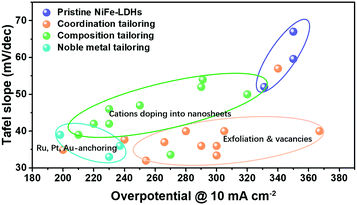 | ||
| Fig. 14 Summary of the representative studies on tailoring active sites on NiFe-LDHs for improving OER activity. | ||
4.4 Host–guest interaction in LDHs
The host–guest interaction in LDHs172–174 serves as a significant characteristic and can be used to modulate the electronic structure of LDHs. By using an inert atmosphere (normally N2) and a precisely controlled synthetic environment (e.g., in boiled water), the carbonate in the LDH interlayers can be substituted with other anions, although the carbonate intercalated LDHs are thermodynamically more favourable. Thus, it provides rich opportunities to study the effect of host–guest interaction between the layers and the intercalated anions in LDHs for the OER.Based on the different radii of the intercalated anions, a common host–guest interaction in LDHs for the OER was studied and the relationship between basal spacing and OER activity was revealed. Xu and Hao prepared NO3− and CO32− intercalated NiFe-LDHs and compared the OER activity differences. They showed that the larger the basal spacing of the NiFe-LDHs, the lower the charge transferring resistance (Rct) at the corresponding electrode/electrolyte interface, and the more the favourable OER kinetics.175 Later, Guan et al. intercalated formamide molecules into the interlayers of NiFe-LDHs by ultrasonic irradiation,176 which increased the basal spacing of the NiFe-LDHs from 7.8 Å to 9.5 Å. As a result, the overpotential for the OER to reach 10 mA cm−2 current density reduced from 256 mV to 210 mV. Jin et al. proposed dodecyl sulfate (DS−) intercalated NiFe-LDHs which could protect the LDHs from carbonate attacking to some extent (Fig. 15a).177 The DS−-intercalated NiFe-LDHs with 2.39 nm interlayer spacing (significantly larger than that of CO32−–NiFe-LDHs, 0.79 nm) exhibited 41 mV lower overpotential at 10 mA cm−2 than that of CO32−–NiFe-LDHs, which can be attributed to the increased electrochemical surface area. Komarneni et al. intercalated dicarboxylic acids, adipic acid and succinic acid into the interlayer spaces of NiFe-LDHs and studied the effect of basal spacing on the OER activity.178 Their findings suggested that the pillaring of NiFe-LDHs with large organic anions was a promising method to create LDH-type high-performance catalysts for the OER in a pH-near-neutral electrolyte. The enlarged basal spacing in the above studies benefited the OER performance of the LDHs by providing more space for mass diffusion and exposing more inner active sites for oxygen evolution. This conclusion agrees well with the studies on LDH exfoliation, as the infinite increase of the basal spacing of LDHs would mean a full exfoliation of LDH nanosheets. However, these studies only placed emphasis on the mass transfer during oxygen evolution, and the effect of host–guest interaction on the intrinsic OER activity of NiFe-LDHs was less well understood. In 2016, Hunter et al. introduced various anions into the interlayers of NiFe-LDHs via the ion-exchange method and studied the relationship between the intercalated anions and the corresponding OER activity of the NiFe-LDHs (Fig. 15b).179 First of all, the authors indeed found a linear correlation of the measured basal spacing with anionic radius, confirming the successful intercalation into the NiFe-LDHs. However, different from the positive relationship between the enlarged basal spacing and enhanced OER activity, the authors discovered a strong correlation between the OER activity and the pKa values of the conjugated acids of the interlayer (anions’ Brønsted or Lewis basicity), e.g., the larger the pKa, the higher the OER activity of the corresponding NiFe-LDHs.
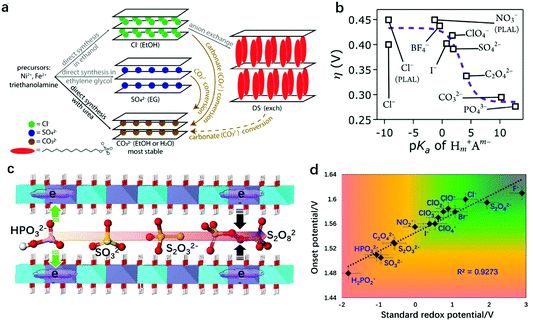 | ||
| Fig. 15 Effect of host–guest interaction between the LDH nanosheets and intercalated anions on OER activity. (a) Schematic description of the synthetic procedures and anion exchange route with structural illustrations of NiFe-LDH products containing carbonate, chloride, sulfate, and dodecyl sulfate anions in the interlayer gallery, which eventually convert to carbonate-intercalated LDHs. Reproduced with permission.177 Copyright 2018, The American Chemical Society. (b) Overpotential (η) of the OER on NiFe-LDHs with different interlayer anions at 1 mA cm−2 in virtually carbonate-free electrolyte as a function of anion basicity. Reproduced with permission.179 Copyright 2016, The Royal Society of Chemistry. (c) Schematics of NiFe-LDHs intercalated with different redox active anions. (d) Relationship between the OER onset potential measured at 1 mA cm−2 on the as-prepared NiFe-LDHs and the corresponding standard redox potential of the intercalated anions. Reproduced with permission.180 Copyright 2018, Springer. | ||
Later on, Sun and Zhou correlated the intercalated anions and the OER performance of NiFe-LDHs from a different viewpoint.180 In consideration of the facts that the OER depends highly on the redox activity of metal sites on LDHs, and that the redox activity of metal sites can be modulated via electronic effects between intercalated anions and metal sites on the nanosheets, the authors intercalated sixteen species of anions with distinct redox activities (SO32−, SO42−, S2O82−, HPO32−, Cl−, NO3−, CO32−, C2O42−, PO43−, ClO4−) into the interlayers of the NiFe-LDHs, separately (Fig. 15c). The intercalated anions with a strong reducing ability can donate electrons to metal sites on the LDH nanosheets, while anions with an oxidizing ability would withdraw electrons from metal sites on the LDH nanosheets via electronic effects. The OER activity of the NiFe-LDHs was plotted as a function of the standard redox potential of the intercalated anions, as shown in Fig. 15d. It shows that the lower the standard redox potential (i.e., the stronger reducing ability), the higher the OER activity of the NiFe-LDHs. The enhanced OER activity can be attributed to the high electron-density of metal sites in the laminate, which can facilitate the de-protonation and adsorption of oxygenated intermediates on the active sites. These two studies provided theoretical insights, from a “chemical perspective”, into design of efficient OER catalysts based on LDHs, showing that the host–guest interaction can serve as a new dimension to tailor the deprotonation step of the OER on the NiFe-LDHs.
4.5 Compositing LDHs with carbon nanomaterials for the OER
Besides the intrinsic activity modulation of LDHs, integrating LDHs with nanostructured carbon materials (graphene oxide, carbon nanotubes, carbon quantum dots) can also benefit the OER performance of the hybrid catalysts by exposing more active sites and facilitating electron transfer, which are indispensable for eletrocatalysts. Dai et al. used mildly oxidized multiwalled CNTs as the substrate for the growth of NiFe-LDHs; the electrostatic force between negatively charged functional groups on the CNTs can adsorb positively-charged metal cation precursors (Fig. 16a).104 Then the composites prepared by solvothermal treatment exhibited outstanding OER performance due to more exposed active sites and the faster electron transfer (Fig. 16b). Sun et al. reported the in situ growth of NiCoFe-LDHs on nitrogen-doped graphene oxide (GO), also assisted by electrostatic force; array-like LDHs on graphene oxide composites, with highly open channels for electrolyte penetration and gas evolution, were prepared and they showed excellent OER performance.181 Yang et al. fabricated NiFe-LDH/rGO composites as shown in Fig. 16c and d, and by virtue of the high electron conductivity of rGO, the overall OER performance of the composites was improved, achieving an onset potential as low as 1.425 V (vs. RHE) as shown in Fig. 16e.182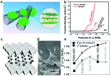 | ||
| Fig. 16 Compositing LDHs with carbon nanomaterials for enhancing OER activity. (a) Schematic showing the hybrid architecture and LDHs’ crystal structure. (b) IR-corrected polarization curves of the NiFe-LDH/CNT hybrid and Ir/C catalyst on a glassy carbon electrode in 0.1 and 1 M KOH. Reproduced with permission.104 Copyright 2013, The American Chemical Society. (c) Schematic showing of compositing NiFe-LDHs with GO. (d) Morphology of the LDH/GO hybrid; the arrows point to LDH nanosheets. The scale bar is 200 nm. (e) The onset potential (Eonset) and the potential required to reach 10 mA cm−2 (Ej = 10 mA cm−2) of the OER catalysed by the catalysts employed. Reproduced with permission.182 Copyright 2014, Wiley-VCH Verlag GmbH & Co. KGaA, Weinheim. | ||
5. Long-term stability of LDHs for the OER
Although significant efforts have been made in the fields of active site identification, OER mechanistic study and efficient catalyst preparation, the bottlenecks hindering the application of LDHs for industrial scale water splitting are the phase transformation183,184 and dissolution184 of LDHs at high working potentials. The decay and dissolution mechanisms have been studied by several groups and the progress achieved can be helpful in designing stable OER catalysts based on LDHs and overcoming the intrinsic weakness.Liu et al. studied the dissolution mechanism of LDHs during oxygen evolution by both operando electrochemical and isotope-labelling characterization studies,185 finding that the interlayer OH− in bulk NiFe-LDHs was involved in the oxygen evolution process and the sluggish diffusion of proton acceptors (e.g., OH−) into the NiFe-LDH interlayers during the OER caused the dissolution of the NiFe-LDHs, resulting in a decrease in OER activity with time. As shown in Fig. 17a, in a high concentration of alkaline medium, the fast penetration of OH− from electrolyte would compensate for the consumption of interlayer OH−, leading to a less significant decrease of local pH; however, in neutral electrolyte, the large size of HPO42− ions (as an example) would make it hard for them to diffuse into the NiFe-LDH interlayers, resulting in a significantly decreased local pH (from basic to acidic) and the corresponding dissolution of the NiFe-LDHs.
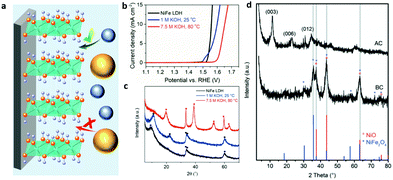 | ||
| Fig. 17 Structural evolution of LDHs for the OER. (a) A schematic illustration showing the NiFe-LDHs on the substrate with different accessibility to proton acceptors. Blue balls represent OH− and yellow balls represent HPO42−. Reproduced with permission.185 Copyright 2019, Wiley-VCH Verlag GmbH & Co. KGaA, Weinheim. (b) Linear sweep voltammograms at a scan rate of 5 mV s−1 and 1600 rpm. (c) X-ray diffractograms for NiFe-LDHs (black), and NiFe-LDHs after immersion for 60 h in 1.0 M KOH at 25 °C (blue) and 7.5 M KOH at 80 °C (red) (● = NiFe-LDHs, ■ = β-Ni(OH)2). Reproduced with permission.186 Copyright 2018, Wiley-VCH Verlag GmbH & Co. KGaA, Weinheim. (d) XRD patterns of the calcined NiFe SDS/pBO composite (NiFe/C) before (BC) and after (AC) potential cycling in 0.1 M KOH, NiO (°) and NiFe2O4 (*) are reference patterns. Reproduced with permission.187 Copyright 2017, WILEY-VCH Verlag GmbH & Co. KGaA, Weinheim. | ||
Andronescu and Schuhmann evaluated the chemical and structural stability of NiFe-LDHs under conditions akin to practical electrolysis and tracked the decay of the OER activity of LDHs under working conditions.186 As shown in Fig. 17b, no significant electrochemical performance changes were detected for the NiFe-LDHs immersed in 1.0 M KOH at 25 °C for 60 h. After working at 25 °C for 60 h, only an additional 30 mV overpotential was required to achieve 10 mA cm−2 current density compared to pristine NiFe-LDHs. However, once the NiFe-LDH electrode was immersed in 7.5 M KOH at 80 °C and worked for 60 h, around 90 mV higher overpotential was required to deliver the same current density. Then the XRD patterns were collected to trace the OER activity decay of the NiFe-LDHs. Also shown in Fig. 17c, NiFe-LDHs that worked in 1 M KOH for 60 h at ambient temperature exhibited a small structural evolution as revealed by X-ray diffraction. The (003) reflection peak shifted to higher values due to the decrease in the basal spacing caused by restructuring of the material or replacement of the NO3− with CO32−; however, the diffraction peaks at 2θ = 11.28 and 22.48° disappeared and new peaks emerged, corresponding to β-Ni(OH)2 isomorphous with brucite. Further revealed by TEM, minor non-homogeneously distributed crystalline domains of α-FeOOH were also observed. Thus, how to maintain or protect the structure of LDHs against high temperatures and high concentrations of electrolyte is a matter of great urgency.
Aiming to solve the above stability issue of NiFe-LDHs for the OER, Schuhmann et al. prepared NiFe-LDH/pBO (polybenzoxazine) nanocomposites via a calcination approach (resulting in NiFe/C).187 As shown in Fig. 17d, the XRD pattern of NiFe/C before potential cycling (BC) showed four major reflections indexed to the NiFe2O4 and NiO. However, the NiFe-LDHs recovered the layered structure with OH− as the interlayer anion with typical (003), (006), and (012) reflections, respectively, which is due to the memory effect of NiFe-LDHs. The carbon matrix derived from pBO served as a stabilizer to NiFe-LDHs for the OER against high temperature (60 °C), high working current density (200 mA cm−2) and a saturated KOH (5 M) conducting environment; nevertheless, further consideration is still needed to see if carbon materials would be stable in the high oxidation potential range.
From the above work we may draw the conclusion that the fast exchange of interlayer OH− with electrolyte and the protection of NiFe-LDHs using additional matrices or substrates from phase or structural transformation are the two key factors in solving the stability issue of the LDHs in applying them as catalysts for the OER. These two requirements can naturally guide us to combine another merit in designing efficient LDH-based electrodes for the OER, the nanoarray electrode structure; and more than that, the nanoarray offers a further advantage which will be elaborated in the following section.
6. Superaerophobic nanoarrays of LDHs for enabling a rapid current increase during the OER
The OER involves tri-phase participation: electrode as the solid phase, electrolyte as the liquid phase, and oxygen bubbles as the gas phase. In a gas evolution reaction, the generated oxygen gas bubbles tend to adhere onto the electrode surface until the buoyancy is large enough to overcome the adhesion force. These strongly adhered bubbles will cover a large area of the electrode surface, the diffusion of the electrolyte through the bubble film will be very difficult with an enlarged diffusion resistance, and consequently the OER will be inhibited, leading to a slow current increase rate with a high overpotential. In Sections 3 and 4, we discussed the identification and regulation of active sites on LDHs regarding charge transfer between active sites and adsorbents, while the mass transport onto the electrode was almost untouched as efforts from a new perspective are required, e.g., how to accelerate gas release/detachment from the electrode surface? In this section, assembling LDHs into nanoarray electrodes with superwetting behaviours, to facilitate electrolyte (liquid) penetration and, at the same time, benefit oxygen bubble (gas) release, will be highlighted and thoroughly discussed. Then, the corresponding characterization and applications of the LDH nanoarray electrodes with superwetting properties for enhancing OER performance will be summarized.6.1 Design of LDH based superaerophobic nanoarrays
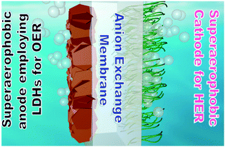
For gas evolution reactions, a high-performance electrode surface requires a strong affinity to liquid electrolyte while being capable of repelling the gas phase. Therefore, a superaerophobic surface with a high bubble contact angle (usually α > 150°), accompanied by a low bubble adhesion force, is an ideal candidate. For instance, MoS2 nanosheet arrays188 and CoS2 microwire arrays189 reported in 2014 both showed superaerophobicity for hydrogen evolution (Fig. 18a). In the same year, a superaerophobic nanoarray of NiFe-LDHs was demonstrated to be highly effective for oxygen evolution and adopted for achieving the world-record performance towards solar-to-hydrogen conversion190,191 (Fig. 18b). A common point that can be observed from the above studies is that the nanostructured electrodes had high surface roughness, which can cut three-phase contact lines (TPCL) at the bubble/electrode interface into discontinuous dots and benefit the bubble release. Afterwards, a series of studies concerning superaerophobic electrodes were reported.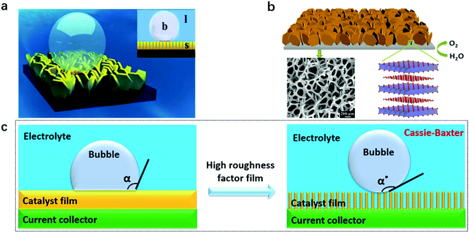 | ||
| Fig. 18 Concepts and models for designing a superaerophobic nanoarray as an enabling electrode for gas evolution reactions. (a) A schematic illustration of a bubble on a superaerophobic electrode surface. Inset: b stands for bubble, l stands for liquid, and s stands for solid. Reproduced with permission.188 Copyright 2014 Wiley-VCH Verlag GmbH & Co. KGaA, Weinheim. (b) NiFe-LDH nanoarrays prepared on nickel foam. The SEM image below shows a porous electrode. Reproduced with permission.190 Copyright 2014, The Royal Society of Chemistry. A schematic illustration of (c) aerophobic and (d) superaerophobic surfaces based on the nanoarray structure. Reproduced with permission.192 Copyright 2018, The American Chemical Society. | ||
Several factors for constructing designed superaerophobic surfaces need to be clarified. Young's equation was used to describe hydrophobicity under ideal conditions, by balancing the forces at the three-phase contact lines; thus a model (eqn (1)) is proposed for (super)aerophobicity analysis:
γSL = γSV + γLV![[thin space (1/6-em)]](https://www.rsc.org/images/entities/char_2009.gif) cos cos![[thin space (1/6-em)]](https://www.rsc.org/images/entities/char_2009.gif) α α | (1) |
Based on this hypothesis, the Cassie–Baxter equation (eqn (2) and Fig. 18c)192 is introduced to investigate the influence of surface architectures, which is essential for achieving superaerophobicity underwater.
cos![[thin space (1/6-em)]](https://www.rsc.org/images/entities/char_2009.gif) α* = r α* = r![[thin space (1/6-em)]](https://www.rsc.org/images/entities/char_2009.gif) cos cos![[thin space (1/6-em)]](https://www.rsc.org/images/entities/char_2009.gif) α α | (2) |
cos![[thin space (1/6-em)]](https://www.rsc.org/images/entities/char_2009.gif) α* = −1 + fs(cos α* = −1 + fs(cos![[thin space (1/6-em)]](https://www.rsc.org/images/entities/char_2009.gif) α + 1) α + 1) | (3) |
6.2 Construction of LDH nanoarrays
It is known that a suspension of LDH nanosheets can be directly introduced onto an electrode by the traditional dipping or spin-coating methods. However, these approaches usually led to the aggregation of nanoparticles and stacking of nanosheets on the electrode surface, which in turn weakened the superaerophobicity of the electrode and limited its electrochemical performance towards the OER. At the same time, physical contact of the LDHs with the electrode substrate could not ensure a stable loading of the LDH catalyst materials on the substrate, as the detachment of bubble films during the OER would cause a severe dragging force and peel off the catalyst layer consequently, resulting in the deterioration of the durability. Therefore, the accomplishment of LDH nanoarray electrodes can not only benefit efficient mass transport but will also be suitable for maintaining electrode integrity and stability. On the other hand, LDH nanoarrays can be grown directly on the surfaces of conducting substrates (e.g., ITO, carbon or metals) by an in situ growth approach. The key strategies to build LDH nanoarrays are through interfacial reaction engineering and avoiding self-nucleation in the bulk solution. To prepare the nanoarrays by chemical bath deposition, the surfaces of substrates should be well cleaned (e.g., acid washing on Ni foam or plasma treatment on ITO glass). Urea was used as a pH adjustor, which would release ammonia by hydrolysis and increase the pH value slowly. The slowly increased OH− concentration leads to mild oversaturation and favours the interfacial precipitation of LDHs. The in situ growth of LDHs usually results in an oriented and rigid nanoplatelet array architecture, which allows for easy access of the electrolyte onto the nanosheets and thus improves the overall performance of LDH based electrodes. For instance, Wei et al. reported the synthesis of NiMn-LDHs on CNTs modified with functional groups (e.g., –OH, –COO) (Fig. 19a). The electronegative –OH and –COO served as nucleation sites capable of anchoring Ni and Mn ions and guaranteed the in situ growth of NiMn-LDHs.193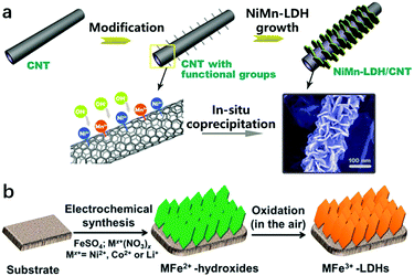 | ||
| Fig. 19 Preparation methods for LDH nanoarrays. (a) A schematic illustration of the synthesis and morphology of NiMn-LDHs/CNTs. Step (I): the surface modification of CNTs with functional groups (e.g., –OH, –CO, –COO). Step (II): the grafting of NiMn-LDH nanosheets onto the CNTs by an in situ growth method. Reproduced with permission.193 Copyright 2014 Wiley-VCH Verlag GmbH & Co. KGaA, Weinheim. (b) A schematic illustration of the electrodeposition route for preparing MFe-LDH (M = Co, Ni and Li) nanoarrays. Reproduced with permission.194 Copyright 2015, The Royal Society of Chemistry. | ||
Electrodeposition or interfacial etching can also be used for the construction of LDH nanoarrays with a high efficiency. The electrodeposition method can shorten the preparation time for LDH nanoarrays to hundreds of seconds. Li et al. prepared Fe-containing LDHs with different divalent metal ions by using the electrosynthesis method (Fig. 19b). This was achieved by controlling the reduction reactions occurring on the working electrode, in which the resulting OH− leads to the precipitation of MxFe1−x(OH)2.194 Furthermore, some recent reports have shown that LDH nanoarrays can also be prepared without using additional precursors; the metal foam itself can be used as both a reactant and a substrate; for example, NiFe foam can be used to prepare NiFe-LDHs via the hydrothermal in situ growth method.195
6.3 Characterization of superaerophobic nanoarrays
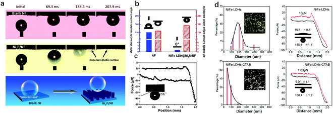
The typical surface bubble behaviour measurements include gas bubble contact angles, adhesion force, advancing/receding angles and contact angle hysteresis.196,197 These are commonly used to characterise the superaerophobicity of an electrode. Among all the reported approaches, the bubble attachment behaviour (adhesion force) on an electrode and the contact angle of the bubble on the electrode can be obtained by using a high-speed camera.As shown in Fig. 20a, Yu et al. reported the study of superwetting behaviour between a bubble and an electrode.198 As can be clearly observed, a bubble is readily pinned on the surface of bare nickel foam (NF) and without shape evolution within the time range studied, i.e., 69.3 to 207.9 ms; whereas a bubble on a superaerophobic electrode has a larger contact angle than that on the NF and can bounce on and gets released more rapidly from the electrode surface. The schematic illustration below revealed that the generated bubbles adhered onto the surface of the bare NF and induced an isolated zone, in contrast to a limited covered area induced by a bubble on a superaerophobic electrode. Pang et al. studied both the bubble and electrolyte droplet contact angle on bare NF and NiFe-LDH@Ni3N-NF.199 As shown in Fig. 20b, the NF exhibited both hydrophobicity and aerophobicity (CA > 120°), while NiFe-LDH@Ni3N-NF showed superhydrophilicity (0°) and superaerophobicity (153.6°). The electrochemical data showed that the superhydrophilicity and superaerophobicity of NiFe-LDH@Ni3N-NF can benefit the ion transport at the electrode/electrolyte interface as well as expose more active sites by accelerating bubble release. This work highlighted the effectiveness of hierarchical structure in modulating the superwetting behaviour of the electrode and contributing to its enhanced electrochemical performance.
 | ||
| Fig. 20 Measurements of superaerophobic nanoarrays. (a) Digital images of hydrogen bubbles on blank nickel foam (NF) and Ni2P/NF, showing the pinning and bouncing states of one bubble on the electrode. The schematic illustration below shows the adhesion behaviour of one H2 bubble on the blank NF (left) and Ni2P/NF nanoarrays (right). The contact area is an “isolated zone” due to the bubble effect. Reproduced with permission.198 Copyright 2019, The American Chemical Society. (b) Static electrolyte droplet contact angles (blue) and air bubble contact angles under electrolyte (red) at the Ni foam and NiFe LDH@Ni3N/NF. Reproduced with permission.199 Copyright 2020, The Royal Society of Chemistry. (c) Adhesive behaviour of a gas bubble on a (Ni0.33Fe0.67)2P electrode; inset: the bubble contact angle (≈158° ± 1.2°) suggests a negligible interaction between the electrode and gas bubble. Reproduced with permission.200 Copyright 2017, Wiley-VCH. | ||
The adhesion force measurement between bubbles and electrode surfaces is another tool for studying the superwetting behaviour of an electrode. The interaction force between the gas bubbles and electrode interfaces can be assessed using a high-sensitivity micro-electromechanical balance system. In detail, a 2 μL gas bubble (the buoyancy can be roughly neglected) was suspended on a metal ring in electrolyte, and the force of this balance system was initially set to zero. Subsequently, the electrode surfaces were brought into contact with the gas bubble at a moving rate of 0.02 mm·s−1. The force was increased gradually until it reached the maximum, and the shape of the air bubble changed from spherical to elliptical. Subsequently, when the electrode moved down further, the contact was reduced sharply to almost zero and the shape of the air bubble changed back to spherical. The critical force to which the gas bubble was subjected can be regarded as the adhesive force between the electrode surface and the gas bubble. As shown in Fig. 20c, the bubble adhesion force on a superaerophobic electrode was rather small, indicating that a superaerophobic electrode can benefit from bubble release and have a positive effect on the gas evolution reaction.200
The advancing/receding contact angles (θA and θR) can be obtained by using a microbalance in a tensiometer,201 and reflect the solid/gas wetting behaviour. Similar to the adhesion force measurement device, the advancing/receding contact angles were used rather than the force between a bubble and a solid surface. For aerophilic surfaces, their θR is <90°. These surfaces exhibited strong affinities, as indicated by the residual bubble in the pull-off experiments, whereas aerophobic surfaces were shown to have little affinity with bubbles, and their θR is >90°.
6.4 Application of superaerophobic nanoarrays of LDHs for the OER
Due to the merits of superaerophobic nanoarrays for gas evolution reactions (OER, for example), LDH nanosheets were assembled on various substrates to prepare superaerophobic electrodes for the OER. Metallic foams, carbon nanotubes, doped graphene oxides, carbon clothes and metal hydroxide nanowires that have high specific area, excellent electronic conductivity and available anchoring sites for LDH nucleation are commonly used as substrates for the preparation of superaerophobic LDH nanoarrays. Xue et al. used a nonwoven stainless-steel fabric (NWSSF) with varied interconnected pore channels as substrates to prepare NiFe-LDH nanoarrays.202 As reported in this work, LDHs grown on the NWSSF had the largest bubble contact angle compared with LDHs grown on NF or ordinary SSF, further suggesting the lowest OER onset potential and the fastest current density increase among the three samples. Wu et al. decorated NiFe-LDHs on NiFe alloy via an in situ method to improve the intrinsic activity for the OER.203 The exposure of active sites could improve the interlayer electron and ion transfer in the FeNi-LDH/FeNi nanoarrays. This in turn jointly contributed to the record low overpotential of 90 mV for the OER onset and the smallest overpotential of 130 mV for the OER at 10 mA cm−2 in alkaline electrolyte. A Ce-doped NiFe-LDH nanosheet/carbon nanotube hierarchical nanocomposite was designed and prepared by Tang et al. for enhanced OER activity,204 in which the Ce doping increased the intrinsic activity of the nanocomposite and the hierarchical structure benefited electrolyte contacting with edge sites on the LDHs. In addition, the hierarchical structure based on the interaction between the LDH nanosheets and carbon nanotubes exhibited superaerophobic properties, benefiting oxygen gas bubble release for enabling a fast increase in the reaction rate (current) during the OER.The superaerophobic properties of LDH nanoarrays can be further strengthened by using other materials. Xie et al. modified NiFe-LDH nanoarrays with Cetyltrimethyl Ammonium Bromide (CTAB), on which the bubble adhesion force was as low as 1.03 μN, demonstrating an excellent superaerophobicity of the electrode. In OER measurement, the NiFe-LDHs modified with CTAB illustrated the smallest bubble released size, though their intrinsic activity remained almost unchanged. Furthermore, metal oxide/hydroxide nanowires can also be used to construct superaerophobic OER electrodes. Sun et al. reported ultrathin NiFeCo-LDH nanosheets decorated on Co2(OH)2CO3 nanowires with merits that include a highly exposed active area and an accelerated bubble release for oxygen evolution. Cu nanowires have also been used as substrates for the preparation of LDH nanoarrays for the OER. The vertically aligned NiFe-LDH nanosheets provide open-channels for effective gas release and OH− penetration, resulting in high current densities of 10 and 100 mA cm−2 at overpotentials of 199 and 281 mV, respectively; which significantly surpass the results obtained from pure NiFe-LDHs.205 Then researchers have tried to combine merits both in the site-tailoring and the construction of superaerophobic nanoarrays based on LDHs together, to design an outstanding OER electrode. Cai et al. carried out a study using Fe2+ to substitute Ni2+ in LDH nanosheets, and simultaneously constructed NiFe2+Fe3+-LDH nanoarrays for the OER. The NiFe2+Fe3+-LDH arrays exhibited an impressive low OER overpotential of 195 mV at 10 mA cm−2, which is 54 mV lower than that on colloidal NiFe2+Fe3+-LDHs. This work combines both the advantages from the modulation of intrinsic activity and the optimization of gas evolution behaviour, showing an outstanding performance of the OER on the LDH arrays. Wang et al. further prepared LDH-based nanoarrays coupled with MoS2, which exhibited remarkable superaerophobicity for enhancing the OER efficiency; the intrinsic activity and fast bubble release of the composite jointly contribute to their excellent overall water splitting performance.206
6.5 Superaerophobic nanoarrays of LDH derivatives for the OER
A topotactic transition involves a structural change to a crystalline solid, which may include loss or gain of material; and the crystal lattice of the product phase shows one or more, crystallographically equivalent, orientational relationships with the crystal lattice of the parent phase.The topotactic derivatives from LDH nanoarrays prepared under mild conditions can potentially inherit the structural and morphological characteristics of the LDHs,207,208 namely, the single atomic dispersion of high valence metal ions and nanosheet morphology. Besides, the degree of topotactic transition and controlled post-oxidation can largely decide and optimize the electronic structure of metal sites in materials, providing excellent opportunities for the design of efficient OER electrodes. The assembly of topotactic derivatives as nanoarray electrodes for the OER, involving catalytic electrode design at the materials level and architecture level, has also been studied widely.
The topotactic conversion from ultrathin metal hydroxides to metal was first studied by Kuang et al., where NiOH was transformed into Ni metal nanosheets.209 Thereafter, the same conversion strategy was applied to convert LDHs to metal alloys.210 The authors prepared single crystalline alloy nanosheets with highly tuneable metallic compositions (NiFe, CoFe, NiCo and NiCoFe) by topotactic reduction of LDHs as the precursors. The single-atomic dispersion of the minor metallic compositions (in that work, Fe) was confirmed by EXAFS as shown in Fig. 21a, in which only Co–Co and Co–Fe bonds but not Fe–Fe bonds were identified in CoFe alloys. The comparison between b1 with b3 in Fig. 21b showed that the obtained CoFe alloy inherited the ultrathin 2D single crystalline structure of the precursor of CoFe-LDHs but showed different crystalline phases. The comparison between b2 and b4 confirmed the elimination of the hydroxyl groups from the LDHs in the in situ topotactic process, leading to the shrinkage of the lattice distance. With a slight oxidation in air, the surface of the metal alloy (CoFe alloy was taken as an example) was converted to a Co/FeO interface, which exhibited an efficient OER catalytic activity, with only a low overpotential of 250 mV required to reach a current density of 10 mA cm−2, as well as a small Tafel slope of 55 mV dec−1, as shown in Fig. 21c.
 | ||
| Fig. 21 Structure, morphology and electrochemical performance of CoFe alloy topotactically derived from CoFe-LDHs. (a) Normalized XANES spectra of Co (left plots) and Fe (right plots) in CoFe alloy nanosheets, and the dispersion of Co and Fe atoms in the alloy (the illustration below). It should be noted that the dashed line (Co foil reference) in the right plots is not the real spectrum but copied from the left plots, and is used only for the comparison of different coordination states. (b) Electron diffraction patterns of a single layer region of CoFe-LDHs (b1) and CoFe alloy nanosheets (b2), and HRTEM images of CoFe-LDH (b3) and CoFe alloy (b4) nanosheets; showing the lattice shrinkage on the basal plane of the nanosheets before and after in situ reduction. (c) Voltammograms showing the OER onset potential and current density as functions of potential on five CoFe alloy nanosheets with different oxidation degrees. Reproduced with permission.210 Copyright 2017, Springer. | ||
In the meantime, some other similar procedures, including sulfurization, phosphorisation, selenization and nitridation, have been carried out on LDHs to prepare highly efficient OER catalysts, though these procedures are not exactly topotactic conversions, because no hard evidence demonstrates that the atomic arrangements of materials before and after reduction procedures matched with their precursors. Nevertheless, a series of highly efficient OER catalysts have been developed by this means. For instance, Du et al. prepared a hydroxide as a precursor and then converted the bimetallic hydroxide into bimetallic phosphide subsequently via a gas phase phosphorisation process.211 The high temperature process did not significantly change the perpendicular nanoplate array structure. The as-prepared FeNiP nanoplate material exhibited a much higher OER activity than benchmark IrO2, and it required an overpotential ∼70 mV lower than that on NiFe-LDHs to reach a current density of 10 mA cm−2. Cao et al. prepared a free-standing electrocatalyst with a vertically oriented Fe-doped Ni3S2 nanosheet array grown on three-dimensional (3D) Ni foam (Fe-Ni3S2/NF), which exhibited high activity and durability for the OER.212 The nanoarray structure of the electrode can benefit the full exposure of the active sites to an electrolyte and the high accessibility of OH− in the electrolyte to the electrode surface. Furthermore, the discontinuous three-phase contact lines (TPCL) can also lower the bubble adhesion force, leading to promoted OER performance on Fe–Ni3S2/NF; that is, a lower overpotential (η) is required for the OER to reach a given current density in comparison with its counterparts. Specifically, the η values required for driving the OER to current densities at 10, 20, and 100 mA cm−2 on Fe 17.5%-Ni3S2/NF are 214, 222, and 249 mV, respectively, which are not only much smaller than the corresponding η values required on Ni3S2/NF (287, 306, and 363 mV) but also very much smaller than those of the benchmark OER catalyst IrOx (347, 377, and 465 mV).
Hu et al. prepared bimetallic (FexNi1−x)2P nanoarrays as OER catalysts in both alkaline and neutral electrolytes. The synthetic process involved the growth of NiFe-LDHs on nickel foam and a second-step of phosphorisation.213 The OER activity was largely enhanced and could be attributed to both the Fe doping and the phosphorisation process; which involved the synergistic effect between Ni and Fe, as well as the hetero-structure interface in the Fe–Ni phosphide derived core–shell hybrids. The optimal composition yielded one of the highest OER activities reported so far, with low overpotentials of 156 mV and 255 mV to drive current densities of 10 mA cm−2 and 500 mA cm−2, respectively. The performance also surpassed those of precious catalysts (IrO2, RuO2) under alkaline conditions. Wang et al. used NiFe-LDHs on nickel foam (NF) as the precursor to prepare iron–nickel sulfide nanowalls on the NF. The edge-exposed morphology of the iron–nickel sulfide nanowalls can benefit the contact between electrolyte and electrodes for OH− penetration, presenting high OER activity with overpotentials of 252 and 297 mV to achieve 100 and 500 mA cm−2, respectively; which were much lower than those of control samples. A similar morphology was observed in Ni- and Se-doped FeOOH, and the synergy between Ni, Fe and Se contributed to greatly enhanced OER performance in terms of low overpotentials of 222, 261, and 279 mV at 10, 50, and 100 mA cm−2, which are 65, 73, and 85 mV lower than those on FeOOH(Se)/NF without Ni.
7. Feasibility of using LDHs as OER catalysts for seawater splitting
Industrial scale water electrolysis leads to a big concern about water supply since current electrolysis technology relies heavily on pure water feeding. Considering the amount of seawater that overweighs the amount of fresh water, electrocatalytic seawater splitting by electrolysis has a profound effect on the development of hydrogen energy and economy.214 However, chloride ions exist in seawater as NaCl (∼0.5 mol L−1), which brings selectivity (OER vs. chloride oxidation reaction, ClOR) and electrode corrosion issues in the anodic reaction.Strasser et al.215 employed NiFe-LDHs as anode catalysts in an alkaline seawater splitting configuration. Under alkaline conditions, ClOR gives hypochlorite with a standard potential of 1.71 V (vs. RHE), which is 480 mV higher than that of OER. Therefore, utilization of LDHs, highly active OER catalysts in alkaline media, could avoid the competing chloride oxidation on the anode within the 480 mV overpotential gap. The faradaic efficiency towards the OER with the molecular oxygen product was tested to be close to 100% under both fresh- and sea-water electrolyte conditions as shown in Fig. 22a. Chen and Yang also studied CoFe-LDHs as efficient anode catalysts for seawater oxidation at near-neutral pH.216 As shown in Fig. 22b, the OER on the CoFe-LDHs required ∼530 mV overpotential to reach a benchmark current density of 10 mA cm−2, which was superior to those on the majority of previously reported catalysts in neutral or near-neutral buffer solutions. It should be noted that the 530 mV overpotential has exceeded the aforementioned 480 mV gap between the OER and ClOR, but the selectivity towards the OER is still around 100%, possibly because of the hydroxide structure of the LDHs that facilitates OH adsorption for the OER instead of Cl adsorption for the ClOR. However, the long-term stability study illustrated that the oxygen evolution current density was only maintained at around 86% of the original value after 8 hours during the chronoamperometry test, probably because of the instability of the LDHs when they are working under near neutral conditions.
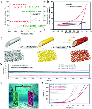 | ||
| Fig. 22 LDHs and their derivatives as OER catalysts for seawater oxidation. (a) OER faradaic efficiency (see the left axis) and current density (see the right axis) achieved on NiFe LDHs supported on carbon, plotted as functions of averaged measured potential during constant current potentiometric steps of 15 min each. The overpotential (η) of approximately 480 mV, corresponding to the design criterion limit, is marked by a dotted vertical line. Reproduced with permission.215 Copyright 2016, Wiley-VCH Verlag GmbH & Co. KGaA, Weinheim. (b) LSV curves of Co-Fe LDHs/Ti and bare Ti electrodes in seawater. Reproduced with permission.216 Copyright 2017, Elsevier Ltd. (c) Schematic drawing of the fabrication process of a dual-layer NiFe-LDH/NiSx-Ni foam (Ni3) anode for seawater splitting, including a surface sulfurization step and an in situ electrodeposition of NiFe-LDHs. (d) Durability tests (1000 h) recorded at a constant current density of 400 mA cm−2 of the seawater-splitting electrolyser using 1 M KOH + real seawater at room temperature (R = 0.95 ± 0.05 ohms), 1 M KOH + 1.5 M NaCl at room temperature (R = 0.8 ± 0.05 ohms), and 6 M KOH electrolyte at 80 °C (R = 0.55 ± 0.05 ohms), respectively. Reproduced with permission.217 Copyright 2019, the authors. | ||
The issue of Cl− corrosion was well-addressed where sulfide was introduced besides the alkaline environment. Kuang et al. combined the merits of LDHs with superhydrophobic structure and a chloride repelling NiFe/NiSx–Ni foam anode structure (referred to as Ni3 for brevity) for seawater splitting.217 Firstly, the surface of the Ni foam was sulfurized with sulfur element in toluene to prepare a NiSx layer, then an OER active NiFe hydroxide was electrodeposited over it via the reduction of nitrate from a solution of Ni(NO3)2 and Fe(NO3)3 (Ni![[thin space (1/6-em)]](https://www.rsc.org/images/entities/char_2009.gif) :
:![[thin space (1/6-em)]](https://www.rsc.org/images/entities/char_2009.gif) Fe = 3
Fe = 3![[thin space (1/6-em)]](https://www.rsc.org/images/entities/char_2009.gif) :
:![[thin space (1/6-em)]](https://www.rsc.org/images/entities/char_2009.gif) 1), as shown in Fig. 22c. The NiSx evolved into a sulfate rich layer to protect the anode from corrosion, while the LDH array served as a highly active OER catalyst. The seawater splitting performance was stable for more than 1000 hours in alkaline seawater solution under conditions typically used in industry, requiring only 1.72 V (vs. RHE) to reach a current density of 400 mA cm−2 in 6 M KOH + 1.5 M NaCl at 80 °C as shown in Fig. 22d. In a real seawater electrolyser, continuous feeding of seawater leads to an increase in NaCl concentration until saturation. Therefore, chloride oxidation and corrosion issues becomes increasingly severe. In a very recent report, seawater electrolysis in saturated NaCl was performed at 500 mA cm−2 for more than 100 h in 6 M NaOH when common-ion effects were introduced with an LDH derived phosphide as a bifunctional electrode,218 which led to stable triple production of H2, O2 and NaCl. Therefore, after the selectivity and corrosion issues mentioned above have been solved, we believe LDHs, and their derivatives, can be employed in alkaline electrolysers for seawater splitting in real applications after adopting appropriate engineering designs such as anti-corrosion electrolyte storage systems, NaCl crystallization units, etc.
1), as shown in Fig. 22c. The NiSx evolved into a sulfate rich layer to protect the anode from corrosion, while the LDH array served as a highly active OER catalyst. The seawater splitting performance was stable for more than 1000 hours in alkaline seawater solution under conditions typically used in industry, requiring only 1.72 V (vs. RHE) to reach a current density of 400 mA cm−2 in 6 M KOH + 1.5 M NaCl at 80 °C as shown in Fig. 22d. In a real seawater electrolyser, continuous feeding of seawater leads to an increase in NaCl concentration until saturation. Therefore, chloride oxidation and corrosion issues becomes increasingly severe. In a very recent report, seawater electrolysis in saturated NaCl was performed at 500 mA cm−2 for more than 100 h in 6 M NaOH when common-ion effects were introduced with an LDH derived phosphide as a bifunctional electrode,218 which led to stable triple production of H2, O2 and NaCl. Therefore, after the selectivity and corrosion issues mentioned above have been solved, we believe LDHs, and their derivatives, can be employed in alkaline electrolysers for seawater splitting in real applications after adopting appropriate engineering designs such as anti-corrosion electrolyte storage systems, NaCl crystallization units, etc.
8. Suggestions on the evaluation of OER performance
Despite the significant progress that has been made in recent years in the synthesis and application of LDHs and their derivatives for the OER, several critical issues still exist in the evaluation of OER performance. Firstly, how to effectively determine the onset potential of the OER on LDHs? As observed in the OER polarisation curves, the LDHs with two or more metals have redox potentials that often interfere or even overlap with the OER onset potentials.Thus, it is difficult to distinguish the oxidation current that arose from oxidation of low valent metal cations and that from the intrinsic OER. Some previous studies may unintendedly state an extremely low onset potential (even close to 1.23 V vs. RHE) achieved; however, in fact, the so-called onset potential may be due to the oxidation of Co2+ or Ni2+, which is noticeably different from the OER onset potential. Such great care is needed when quoting the onset potential of the OER. A practical suggestion is to use the oxidation current increase in the back scan during the cyclic voltammogram measurements where no mixing oxidation current would be produced, to confirm the OER onset potential. Also, the starting point of the Tafel slope and the OER current characterized by steady-state measurements are also considered as reliable methods.
Secondly, how to impartially compare the OER activity on LDHs? To compare the OER current density at a given (over-)potential or to compare the (over-)potential required to drive the OER at a given current density? Which one is more relevant to the fundamental study and/or applied research? In the literature, the current density of 10 mA cm−2 as a target has been used for a long time; however, this geometric activity can be influenced significantly by the catalyst loading, electrode structure and electrochemical surface area, which in turn can lead to confusion. The Tafel slope value can serve as an alternative to characterize the OER activity of LDHs, and the TOF, which takes into account a number of parameters that include the current density (J) at a given overpotential, the surface area of the electrode (A), the Faraday constant (F), and the number of moles of metal on the electrode (m), has received increasing attention.62 Although the TOF is not as direct as the overpotential value that is required to drive 10 mA cm−2 current density in comparing the OER activity, it is more reliable and can be used for the comparison between different types of catalysts/electrodes; therefore we strongly recommend using the Tafel slope or TOF as a general index to evaluate the OER activity of electrocatalysts. Furthermore, the characterization conditions, including the pH value, potential scan rate in the voltammograms, selection of electrolyte, should also be stated clearly or even unified.
Thirdly, how to measure the electrochemical accessibility of metal sites on LDHs? What would be a standard loading of LDHs on electrodes? Traditionally, the electrochemical surface area (ECSA) calculated from capacitance has been widely used to evaluate the electrochemical accessibility of electrocatalysts. However, only catalyst materials with excellent electronic conductivity are applicable for this method. The electron transport is relatively sluggish due to the low conductivity of LDHs, which makes using capacitance unsuitable for measuring the ECSA of LDHs. It is worth mentioning that Boettcher proposed an alternative approach, i.e., impedance spectroscopy method, to measure the ECSA in spite of the low conductivity of LDHs.219 Xu also reported several studies trying to come up with reliable methods (surface redox reaction, double layer capacitance, atomic force microscopy and BET method) capable of measuring the electrochemical accessibility.220,221 Furthermore, Simonov et al. studied the catalyst loading effect (from 0.004 mg cm−2 to 0.40 mg cm−2) on the OER performance of NiFe-LDHs.222 The authors found that the high loading of catalysts did not always correlate with a better performance, due to the aggregation of catalysts on the electrode surface. If reliable activity comparisons are to be achieved in this field, the standard measurement of ECSA and loading of catalysts should be unified across the field.
Finally, how to describe the surface chemistry of LDH derivatives? The latter include metal sulphides, selenides, and nitrides as electrocatalysts under OER working conditions. Although the topotactic derivatives of LDHs have already been intensively used as OER catalysts for water splitting, identifications of the active sites, stable phases and interactions between the outer shell and the inner core (specifically, electron transfer, lattice mismatch) of the derivatives under OER operational conditions are still very challenging. As pointed out by Jin,223 metal chalcogenides, nitrides and phosphides were more likely to be pre-catalysts rather than real functioning catalysts. The surface oxidation of metal sulphides/phosphides during the OER would be inevitable, and it was the converted metal oxides/hydroxides that accounted for the OER activity, while the metal chalcogenides, nitrides and phosphides provided electron transfer channels. Hence, solid evidence is required before the recognition of metal sulphides, selenides, and nitrides as real OER active electrocatalysts. Furthermore, a similar phenomenon may also be found in metal–organic-frameworks (MOFs) as OER active electrocatalysts. Although MOFs have shown excellent OER activity and stability, the post-characterization studies have revealed that metal hydroxides were generated due to the ligand transformation during the OER. The precise identification of the active phase during the OER is also crucial in designing efficient OER electrocatalysts.
9. Concluding remarks and perspectives
2D layered double hydroxides (LDHs) have proven to be a new class of low-cost electrocatalysts for the OER of water splitting in alkaline media, attributed to their unique structural characteristics including tuneable composition, single-atomic dispersion of high valence metallic cations (two or even more species of high valent metallic cations can also be single atomically dispersed) and exchangeable intercalated anions. The comprehensive studies employing advanced experimental and theoretical techniques have provided insights into the OER mechanisms, including identification of active sites on LDHs at atomic and molecular levels. At the material level, enormous progress has been made in the compositional modulation, coordination environment tailoring, and topotactic conversion of LDHs to enhance their reactivity and stability for the OER. At the electrode level, the combination of nanoarray structures with LDHs has been performed to promote mass transportation and gas product release from the electrode to meet the requirements of larger scale electrocatalytic water splitting for green hydrogen production.To use LDHs and their derivatives as efficient OER catalysts in an industrial scale water electrolyser, several other obstacles or challenges cannot be overlooked, as shown in Fig. 23.
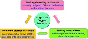 | ||
| Fig. 23 The conceptual sketch represents the perspectives of the future development of LDHs for the OER. | ||
The first grand challenge is to break the scaling relationship for improving the intrinsic reactivity of LDHs towards the OER. Based on theoretical calculations, the OER occurring on a single site requires a minimum overpotential due to the scaling relationship as shown in Fig. 4. Therefore, a bold assumption with the possibility of further enhancing the activity would be to break the scaling relationship during the OER. For example, Xiao et al. used calculations to prove that the active centre involving both Ni and Fe species in NiFe-LDHs showed superior OER activity over a single metal site. This indicates that the overpotential required would be lower when the OER occurred on multi-sites (stereoscopic configuration) involved at the catalytic centre. Li et al. conducted a pioneering experimental study, in which two-phase metal sulphide (LDH derivative) composites jointly contributed to a lower OER onset potential of 1.33 V (vs. RHE).224 This work, along with other LDH derivatives for the efficient OER, may serve as representatives proving that splitting the traditional four-step OER into more steps on multi-sites can lower the energy barrier (i.e., overpotential required). By combining various efforts on identification and tailoring of active sites, including multi-active sites participating in the reaction, there is promising potential to break the scaling relationship, lower the reaction barriers and further improve the intrinsic reactivity of LDHs and their derivatives for the OER. In addition, combined with in situ characterization techniques, the well-developed high-level computational chemistry approaches such as molecular dynamics and density functional theory, together with big data, artificial intelligence and machine learning, can also be employed to design and screen new LDH based catalysts, achieving balance between the high intrinsic activities of multi-active sites and high stability under specific reaction conditions, e.g., for large scale (sea)water splitting.
Secondly, how to maintain the chemical and mechanical stability of LDHs at industry standards? This is equally important for the application of LDH-based catalysts in a water electrolyser. From a chemical stability consideration, recent findings have pointed out that anchoring noble metal can be helpful in maintaining the stability of transition metal cations in relatively low valence states without significantly affecting the OER activity;165 however, it would be even better if the stability of LDHs can be maintained without using noble metal. In this regard, Markovic pointed out that adding Fe3+ (0.1 mol L−1) into electrolyte can efficiently prevent the dissolution of active Fe3+ in transition metal (hydro)oxides.225 The Fe3+-containing electrolyte acted like Fe-buffer according to a dissolution–deposition dynamic equilibrium theory. From a mechanical stability viewpoint, the in situ grown nanoarray electrode based on LDHs and their derivatives is significantly superior over the corresponding electrode prepared by the traditional spraying or dip-coating method. The nanoarray electrode removes the binder and there is a stronger interaction between the current collector and active catalyst materials. The latter can protect the active materials from falling off from the current collector, and the electrodeposition method would be feasible for preparing large scale nanoarray electrodes.
The third key challenge is to effectively embed LDHs onto anion exchange membranes (AEMs), to prepare a stable nanoarray electrode-based membrane–electrode-assembly (MEA) for highly efficient large-scale electrochemical water splitting. Zhuang et al. reported the combination of AEMs with Ni-Fe catalysts for pure water splitting,226 and Koshikawa et al. also reported the use of NiFe-LDHs as anodes on MEAs for water splitting.227 However, the MEA fabrication involved using carbon black as a diluent and Nafion solution as the binder, which leads to additional resistance in charge transport during the OER and overall water splitting. As aforementioned, in situ decorating LDHs onto AEMs via electrostatic attractive force and nucleation can largely avoid the use of binder and thus improve the mechanical stability of electrodes compared with those prepared by simple spraying. However, the successful decoration of LDHs on AEMs requires defects on AEMs as nucleation sites, which can irreversibly interfere with the anion selective permeability and membrane stability. Therefore, further work would entail balancing the electronic conductivity and mechanical stability of the electrode, with the membrane selective permeability and superaerophobicity being well engineered. A very recent study on combining NiFeOx with AEMs for pure water electrolysis may serve as an implication for decorating NiFe-LDHs onto AEMs via an in situ method;228 however, the applicable MEA based on LDHs with nanoarray structure for efficient water splitting on a large scale (as shown in Fig. 24) still requires further development.
Finally, from a wider point of view, in addition to water splitting for hydrogen production, the oxygen evolution reaction can be widely coupled with many important reduction reactions (e.g., N2 reduction reaction, CO2 reduction reaction, metal deposition, and hydrogenation reactions) in energy storage and chemical production systems, including but not limited to artificial nitrogen/carbon cycles and metal–air batteries. The mass production of LDHs with desired structure and assembly is important for the industrialization of LDHs in various energy conversion systems. The utilization of the isolated nucleation–crystallization growth method, which produces crystals with uniform composition and structure, should be explored in batch syntheses of colloidal LDHs with optimum compositions, layer numbers and crystal sizes. The state of the art 3D printing technology should be used in large scale assembly of colloidal LDHs into desired macro-structures. Electrodeposition is an efficient method to directly grow LDH arrays on a porous substrate, but the uniformity needs further confirmation when the size of the electrode increases.
Conflicts of interest
There are no conflicts to declare.Acknowledgements
We acknowledge the helpful discussions with Prof. Hongjie Dai (Stanford University), Dr. Weizheng Cai and Mr Junming Zhang (Nanyang Technological University). This work was supported by the National Natural Science Foundation of China (NSFC), the Royal Society and the Newton Fund through the Newton Advanced Fellowship award (NAF\R1\191294), the UKRI/EPSRC (the PhD studentship to X. L. with Project Ref. 2120302 under EP/R513180/1 and the PhD studentship to A. M. with Project Ref. 228419 under EP/S023909/1), the Program for Changjiang Scholars and Innovation Research Team in the University (No. IRT1205), the Fundamental Research Funds for the Central Universities, the long-term subsidy mechanism from the Ministry of Finance and the Ministry of Education of PRC, the start-up fund from Beijing University of Chemical Technology (BUCTRC202025), the fellowship of China Postdoctoral Science Foundation (2020M670107), and the Natural Science Foundation of Beijing, China (2214062).Notes and references
- J. Rossmeisl, A. Logadottir and J. K. Nørskov, Chem. Phys., 2005, 319, 178–184 CrossRef CAS.
- O. Diaz-Morales, S. Raaijman, R. Kortlever, P. J. Kooyman, T. Wezendonk, J. Gascon, W. Fu and M. T. Koper, Nat. Commun., 2016, 7, 12363 CrossRef CAS PubMed.
- O. Diaz-Morales, I. Ledezma-Yanez, M. T. Koper and F. Calle-Vallejo, ACS Catal., 2015, 5, 5380–5387 CrossRef CAS.
- N.-T. Suen, S.-F. Hung, Q. Quan, N. Zhang, Y.-J. Xu and H. M. Chen, Chem. Soc. Rev., 2017, 46, 337–365 RSC.
- L. Han, S. Dong and E. Wang, Adv. Mater., 2016, 28, 9266–9291 CrossRef CAS PubMed.
- Y. Jiao, Y. Zheng, M. Jaroniec and S. Z. Qiao, Chem. Soc. Rev., 2015, 44, 2060–2086 RSC.
- A. Züttel, A. Remhof, A. Borgschulte and O. Friedrichs, Philos. Trans. R. Soc., A, 2010, 368, 3329–3342 CrossRef PubMed.
- Z. W. Seh, J. Kibsgaard, C. F. Dickens, I. Chorkendorff, J. K. Nørskov and T. F. Jaramillo, Science, 2017, 355, eaad4998 CrossRef PubMed.
- M. T. Koper and E. Bouwman, Angew. Chem., Int. Ed., 2010, 49, 3723–3725 CrossRef CAS PubMed.
- C. Dolan, Road Map to a US Hydrogen Economy, http://www.ushydrogenstudy.org.
- J. FCH, Hydrogen Roadmap Europe: A Sustainable Pathway for the European Energy Transition, https://www.fch.europa.eu/news/hydrogen-roadmap-europe-sustainable-pathway-european-energy-transition.
- M. T. Koper, Nat. Chem., 2013, 5, 255–256 CrossRef CAS PubMed.
- S. Lin, M. Harada, Y. Suzuki and H. Hatano, Fuel, 2002, 81, 2079–2085 CrossRef CAS.
- J. Wang, M. Jiang, Y. Yao, Y. Zhang and J. Cao, Fuel, 2009, 88, 1572–1579 CrossRef CAS.
- H. Dau, C. Limberg, T. Reier, M. Risch, S. Roggan and P. Strasser, ChemCatChem, 2010, 2, 724–761 CrossRef CAS.
- Y. Li, H. Wang, L. Xie, Y. Liang, G. Hong and H. Dai, J. Am. Chem. Soc., 2011, 133, 7296–7299 CrossRef CAS.
- D. Voiry, M. Salehi, R. Silva, T. Fujita, M. Chen, T. Asefa, V. B. Shenoy, G. Eda and M. Chhowalla, Nano Lett., 2013, 13, 6222–6227 CrossRef CAS PubMed.
- P. Xiao, M. A. Sk, L. Thia, X. Ge, R. J. Lim, J.-Y. Wang, K. H. Lim and X. Wang, Energy Environ. Sci., 2014, 7, 2624–2629 RSC.
- C. C. McCrory, S. Jung, J. C. Peters and T. F. Jaramillo, J. Am. Chem. Soc., 2013, 135, 16977–16987 CrossRef CAS PubMed.
- S. Du, Z. Ren, Y. Qu, J. Wu, W. Xi, J. Zhu and H. Fu, Chem. Commun., 2016, 52, 6705–6708 RSC.
- M. T. Koper, J. Electroanal. Chem., 2011, 660, 254–260 CrossRef CAS.
- N. S. Lewis and D. G. Nocera, Proc. Natl. Acad. Sci. U. S. A., 2006, 103, 15729–15735 CrossRef CAS PubMed.
- H. N. Nong, L. Gan, E. Willinger, D. Teschner and P. Strasser, Chem. Sci., 2014, 5, 2955–2963 RSC.
- Y. Yao, S. Hu, W. Chen, Z.-Q. Huang, W. Wei, T. Yao, R. Liu, K. Zang, X. Wang and G. Wu, Nat. Catal, 2019, 2, 304 CrossRef CAS.
- Y. Lee, J. Suntivich, K. J. May, E. E. Perry and Y. Shao-Horn, J. Phys. Chem. Lett., 2012, 3, 399–404 CrossRef CAS PubMed.
- V. Alves, L. Da Silva, J. Boodts and S. Trasatti, Electrochim. Acta, 1994, 39, 1585–1589 CrossRef CAS.
- T. Reier, Z. Pawolek, S. Cherevko, M. Bruns, T. Jones, D. Teschner, S. R. Selve, A. Bergmann, H. N. Nong and R. Schlögl, J. Am. Chem. Soc., 2015, 137, 13031–13040 CrossRef CAS PubMed.
- M. E. Lyons and S. Floquet, Phys. Chem. Chem. Phys., 2011, 13, 5314–5335 RSC.
- K. A. Stoerzinger, L. Qiao, M. D. Biegalski and Y. Shao-Horn, J. Phys. Chem. Lett., 2014, 5, 1636–1641 CrossRef CAS PubMed.
- T. Reier, M. Oezaslan and P. Strasser, ACS Catal., 2012, 2, 1765–1772 CrossRef CAS.
- J. Kibsgaard and I. Chorkendorff, Nat. Energy, 2019, 1, 430–433 CrossRef.
- E. Kemppainen, A. Bodin, B. Sebok, T. Pedersen, B. Seger, B. Mei, D. Bae, P. C. K. Vesborg, J. Halme and O. Hansen, Energy Environ. Sci., 2015, 8, 2991–2999 RSC.
- M. Jahan, Z. Liu and K. P. Loh, Adv. Funct. Mater., 2013, 23, 5363–5372 CrossRef CAS.
- X. Xu, F. Song and X. Hu, Nat. Commun., 2016, 7, 12324 CrossRef CAS PubMed.
- L. C. Seitz, C. F. Dickens, K. Nishio, Y. Hikita, J. Montoya, A. Doyle, C. Kirk, A. Vojvodic, H. Y. Hwang and J. K. Norskov, Science, 2016, 353, 1011–1014 CrossRef CAS PubMed.
- J. A. Haber, Y. Cai, S. Jung, C. Xiang, S. Mitrovic, J. Jin, A. T. Bell and J. M. Gregoire, Energy Environ. Sci., 2014, 7, 682–688 RSC.
- X. Zou and Y. Zhang, Chem. Soc. Rev., 2015, 44, 5148–5180 RSC.
- H. Wang, H.-W. Lee, Y. Deng, Z. Lu, P.-C. Hsu, Y. Liu, D. Lin and Y. Cui, Nat. Commun., 2015, 6, 7261 CrossRef CAS PubMed.
- F. Cheng, J. Shen, B. Peng, Y. Pan, Z. Tao and J. Chen, Nat. Chem., 2011, 3, 79 CrossRef CAS PubMed.
- L. Wang, X. Zhao, Y. Lu, M. Xu, D. Zhang, R. S. Ruoff, K. J. Stevenson and J. B. Goodenough, J. Electrochem. Soc., 2011, 158, A1379–A1382 CrossRef CAS.
- T. W. Kim, M. A. Woo, M. Regis and K.-S. Choi, J. Phys. Chem. Lett., 2014, 5, 2370–2374 CrossRef CAS PubMed.
- T. Maiyalagan, K. A. Jarvis, S. Therese, P. J. Ferreira and A. Manthiram, Nat. Commun., 2014, 5, 3949 CrossRef CAS PubMed.
- C. Li, X. Han, F. Cheng, Y. Hu, C. Chen and J. Chen, Nat. Commun., 2015, 6, 7345 CrossRef CAS PubMed.
- J. Suntivich, K. J. May, H. A. Gasteiger, J. B. Goodenough and Y. Shao-Horn, Science, 2011, 334, 1383–1385 CrossRef CAS.
- E. Fabbri, M. Nachtegaal, T. Binninger, X. Cheng, B.-J. Kim, J. Durst, F. Bozza, T. Graule, R. Schäublin and L. Wiles, Nat. Mater., 2017, 16, 925 CrossRef CAS PubMed.
- K. J. May, C. E. Carlton, K. A. Stoerzinger, M. Risch, J. Suntivich, Y.-L. Lee, A. Grimaud and Y. Shao-Horn, J. Phys. Chem. Lett., 2012, 3, 3264–3270 CrossRef CAS.
- F. Song, K. Schenk and X. Hu, Energy Environ. Sci., 2016, 9, 473–477 RSC.
- A. Grimaud, K. J. May, C. E. Carlton, Y.-L. Lee, M. Risch, W. T. Hong, J. Zhou and Y. Shao-Horn, Nat. Commun., 2013, 4, 2439 CrossRef PubMed.
- J. A. Haber, E. Anzenburg, J. Yano, C. Kisielowski and J. M. Gregoire, Adv. Energy Mater., 2015, 5, 1402307 CrossRef.
- Z. Lu, H. Wang, D. Kong, K. Yan, P.-C. Hsu, G. Zheng, H. Yao, Z. Liang, X. Sun and Y. Cui, Nat. Commun., 2014, 5, 4345 CrossRef CAS PubMed.
- A. Grimaud, O. Diaz-Morales, B. Han, W. T. Hong, Y.-L. Lee, L. Giordano, K. A. Stoerzinger, M. T. Koper and Y. Shao-Horn, Nat. Chem., 2017, 9, 457 CrossRef CAS PubMed.
- S. Jung, C. C. McCrory, I. M. Ferrer, J. C. Peters and T. F. Jaramillo, J. Mater. Chem. A, 2016, 4, 3068–3076 RSC.
- L. Kuai, J. Geng, C. Chen, E. Kan, Y. Liu, Q. Wang and B. Geng, Angew. Chem., Int. Ed., 2014, 53, 7547–7551 CrossRef CAS PubMed.
- M. S. Burke, L. J. Enman, A. S. Batchellor, S. Zou and S. W. Boettcher, Chem. Mater., 2015, 27, 7549–7558 CrossRef CAS.
- H. Yin and Z. Tang, Chem. Soc. Rev., 2016, 45, 4873–4891 RSC.
- C. Tang, H.-F. Wang, H.-S. Wang, F. Wei and Q. Zhang, J. Mater. Chem. A, 2016, 4, 3210–3216 RSC.
- Y. Zhu, Q. Lin, Z. Hu, Y. Chen, Y. Yin, H. A. Tahini, H. J. Lin, C. T. Chen, X. Zhang and Z. Shao, Small, 2020, 16, 2001204 CrossRef CAS PubMed.
- R. P. Forslund, W. G. Hardin, X. Rong, A. M. Abakumov, D. Filimonov, C. T. Alexander, J. T. Mefford, H. Iyer, A. M. Kolpak and K. Johnston, Nat. Commun., 2018, 9, 3150 CrossRef PubMed.
- J. Yu, J. Sunarso, Y. Zhu, X. Xu, R. Ran, W. Zhou and Z. Shao, Chem. – Eur. J., 2016, 22, 2719–2727 CrossRef CAS.
- Y. Zhu, H. A. Tahini, Z. Hu, Y. Yin, Q. Lin, H. Sun, Y. Zhong, Y. Chen, F. Zhang and H. J. Lin, EcoMat, 2020, 2, e12021 CAS.
- Y. Zhang, X. Wang, F. Luo, Y. Tan, L. Zeng, B. Fang and A. Liu, Appl. Catal., B, 2019, 256, 117852 CrossRef CAS.
- F. Song and X. Hu, Nat. Commun., 2014, 5, 4477 CrossRef CAS PubMed.
- X. Cui, B. Zhang, C. Zeng and S. Guo, MRS Commun., 2018, 8, 1230–1235 CrossRef CAS.
- H.-J. Qiu, G. Fang, J. Gao, Y. Wen, J. Lv, H. Li, G. Xie, X. Liu and S. Sun, ACS Mater. Lett., 2019, 1, 526–533 CrossRef CAS.
- W. Dai, T. Lu and Y. Pan, J. Power Sources, 2019, 430, 104–111 CrossRef CAS.
- S. Yagi, I. Yamada, H. Tsukasaki, A. Seno, M. Murakami, H. Fujii, H. Chen, N. Umezawa, H. Abe and N. J. N. C. Nishiyama, Nat. Commun., 2015, 6, 8249 CrossRef PubMed.
- Y. Zhu, W. Zhou, J. Yu, Y. Chen, M. Liu and Z. Shao, Chem. Mater., 2016, 28, 1691–1697 CrossRef CAS.
- Y. Wang, T. Zhou, K. Jiang, P. Da, Z. Peng, J. Tang, B. Kong, W. B. Cai, Z. Yang and G. Zheng, Adv. Energy Mater., 2014, 4, 1400696 CrossRef.
- Y. Zhao, X. Jia, G. Chen, L. Shang, G. I. Waterhouse, L.-Z. Wu, C.-H. Tung, D. O’Hare and T. Zhang, J. Am. Chem. Soc., 2016, 138, 6517–6524 CrossRef CAS PubMed.
- H. Y. Wang, Y. Y. Hsu, R. Chen, T. S. Chan, H. M. Chen and B. Liu, Adv. Energy Mater., 2015, 5, 1500091 CrossRef.
- L. Wang, J. Geng, W. Wang, C. Yuan, L. Kuai and B. Geng, Nano Res., 2015, 8, 3815–3822 CrossRef CAS.
- H. Chen, X. Huang, L. J. Zhou, G. D. Li, M. Fan and X. Zou, ChemCatChem, 2016, 8, 992–1000 CrossRef CAS.
- G. Karkera, T. Sarkar, M. D. Bharadwaj and A. Prakash, ChemCatChem, 2017, 9, 3681–3690 CrossRef CAS.
- G. Gardner, J. Al-Sharab, N. Danilovic, Y. B. Go, K. Ayers, M. Greenblatt and G. C. Dismukes, Energy Environ. Sci., 2016, 9, 184–192 RSC.
- M. Al-Mamun, X. Su, H. Zhang, H. Yin, P. Liu, H. Yang, D. Wang, Z. Tang, Y. Wang and H. Zhao, Small, 2016, 12, 2866–2871 CrossRef CAS PubMed.
- M. Li, Y. Xiong, X. Liu, X. Bo, Y. Zhang, C. Han and L. Guo, Nanoscale, 2015, 7, 8920–8930 RSC.
- J. Zhang, D. Zhang, Y. Yang, J. Ma, S. Cui, Y. Li and B. Yuan, RSC Adv., 2016, 6, 92699–92704 RSC.
- S. K. Bikkarolla and P. Papakonstantinou, J. Power Sources, 2015, 281, 243–251 CrossRef CAS.
- K. Fan, H. Chen, Y. Ji, H. Huang, P. M. Claesson, Q. Daniel, B. Philippe, H. Rensmo, F. Li, Y. Luo and L. Sun, Nat. Commun., 2016, 7, 1–9 Search PubMed.
- C. Zhang, M. Shao, L. Zhou, Z. Li, K. Xiao and M. Wei, ACS Appl. Mater. Interfaces, 2016, 8, 33697–33703 CrossRef CAS PubMed.
- Y. Wang, M. Qiao, Y. Li and S. Wang, Small, 2018, 14, 1800136 CrossRef PubMed.
- Z. Cai, D. Zhou, M. Wang, S.-M. Bak, Y. Wu, Z. Wu, Y. Tian, X. Xiong, Y. Li, W. Liu, S. Siahrostami, Y. Kuang, X.-Q. Yang, H. Duan, Z. Feng, H. Wang and X. Sun, Angew. Chem., Int. Ed., 2018, 57, 9392–9396 CrossRef CAS PubMed.
- P. Zhou, Y. Wang, C. Xie, C. Chen, H. Liu, R. Chen, J. Huo and S. Wang, Chem. Commun., 2017, 53, 11778–11781 RSC.
- Y. Wang, Y. Zhang, Z. Liu, C. Xie, S. Feng, D. Liu, M. Shao and S. Wang, Angew. Chem., Int. Ed., 2017, 56, 5867–5871 CrossRef CAS PubMed.
- L. Chen, H. Zhang, L. Chen, X. Wei, J. Shi and M. He, J. Mater. Chem. A, 2017, 5, 22568–22575 RSC.
- J. Nai, H. Yin, T. You, L. Zheng, J. Zhang, P. Wang, Z. Jin, Y. Tian, J. Liu and Z. Tang, Adv. Energy Mater., 2015, 5, 1401880 CrossRef.
- L. Yu, J. F. Yang, B. Y. Guan, Y. Lu and X. W. Lou, Angew. Chem., Int. Ed., 2018, 57, 172–176 CrossRef CAS PubMed.
- H. Jin, S. Mao, G. Zhan, F. Xu, X. Bao and Y. Wang, J. Mater. Chem. A, 2017, 5, 1078–1084 RSC.
- D. Hall, J. Electrochem. Soc., 1983, 130, 317 CrossRef CAS.
- M. E. Lyons and M. P. Brandon, Int. J. Electrochem. Sci., 2008, 3, 1386–1424 CAS.
- S. Klaus, Y. Cai, M. W. Louie, L. Trotochaud and A. T. Bell, J. Phys. Chem. C, 2015, 119, 7243–7254 CrossRef CAS.
- X. Long, S. Xiao, Z. Wang, X. Zheng and S. Yang, Chem. Commun., 2015, 51, 1120–1123 RSC.
- F.-S. Zhang, J.-W. Wang, J. Luo, R.-R. Liu, Z.-M. Zhang, C.-T. He and T.-B. Lu, Chem. Sci., 2018, 9, 1375–1384 RSC.
- A. Dutta and N. Pradhan, J. Phys. Chem. Lett., 2016, 8, 144–152 CrossRef PubMed.
- G. F. Chen, T. Y. Ma, Z. Q. Liu, N. Li, Y. Z. Su, K. Davey and S. Z. Qiao, Adv. Funct. Mater., 2016, 26, 3314–3323 CrossRef CAS.
- M. Shao, F. Ning, Y. Zhao, J. Zhao, M. Wei, D. G. Evans and X. Duan, Chem. Mater., 2012, 24, 1192–1197 CrossRef CAS.
- Y. Zhao, X. Jia, G. I. Waterhouse, L. Z. Wu, C. H. Tung, D. O'Hare and T. Zhang, Adv. Energy Mater., 2016, 6, 1501974 CrossRef.
- Q. Wang and D. O’Hare, Chem. Rev., 2012, 112, 4124–4155 CrossRef CAS PubMed.
- R. Sasai, H. Sato, M. Sugata, T. Fujimura, S. Ishihara, K. Deguchi, S. Ohki, M. Tansho, T. Shimizu and N. Oita, Inorg. Chem., 2019, 58, 10928–10935 CrossRef CAS PubMed.
- X. Wang, J. Lu, W. Shi, F. Li, M. Wei, D. G. Evans and X. Duan, Langmuir, 2009, 26, 1247–1253 CrossRef PubMed.
- M. Luo, Z. Cai, C. Wang, Y. Bi, L. Qian, Y. Hao, L. Li, Y. Kuang, Y. Li, X. Lei, Z. Huo, W. Liu, H. Wang, X. Sun and X. Duan, Nano Res., 2017, 10, 1732–1739 CrossRef CAS.
- D. Zhou, Y. Jia, X. Duan, J. Tang, J. Xu, D. Liu, X. Xiong, J. Zhang, J. Luo, L. Zheng, B. Liu, Y. Kuang, X. Sun and X. Duan, Nano Energy, 2019, 60, 661–666 CrossRef CAS.
- X. Bo, Y. Li, R. K. Hocking and C. Zhao, ACS Appl. Mater. Interfaces, 2017, 9, 41239–41245 CrossRef CAS PubMed.
- M. Gong, Y. Li, H. Wang, Y. Liang, J. Z. Wu, J. Zhou, J. Wang, T. Regier, F. Wei and H. Dai, J. Am. Chem. Soc., 2013, 135, 8452–8455 CrossRef CAS PubMed.
- D. G. Evans and R. C. Slade, Layered double hydroxides, Springer, 2006, pp. 1–87 Search PubMed.
- M. Gong and H. Dai, Nano Res., 2014, 8, 23–39 CrossRef.
- G. R. Williams, A. I. Khan and D. O'Hare, Layered double hydroxides, Springer, 2006, pp. 161–192 Search PubMed.
- A. I. Khan and D. O’Hare, J. Mater. Chem., 2002, 12, 3191–3198 RSC.
- P. Benito, M. Herrero, F. Labajos and V. Rives, Appl. Clay Sci., 2010, 48, 218–227 CrossRef CAS.
- A. Fogg, V. Green, H. Harvey and D. O'Hare, Adv. Mater., 1999, 11, 1466–1469 CrossRef CAS.
- P. J. Sideris, U. G. Nielsen, Z. Gan and C. P. Grey, Science, 2008, 321, 113–117 CrossRef CAS PubMed.
- X. Guo, F. Zhang, D. G. Evans and X. Duan, Chem. Commun., 2010, 46, 5197–5210 RSC.
- C. Qiao, Y. Zhang, Y. Zhu, C. Cao, X. Bao and J. Xu, J. Mater. Chem. A, 2015, 3, 6878–6883 RSC.
- S. Anantharaj, K. Karthick and S. Kundu, Mater. Today Energy, 2017, 6, 1–26 CrossRef.
- F. Yang, K. Sliozberg, I. Sinev, H. Antoni, A. Bähr, K. Ollegott, W. Xia, J. Masa, W. Grünert and B. R. Cuenya, ChemSusChem, 2017, 10, 156–165 CrossRef CAS PubMed.
- W. Ma, R. Ma, J. Wu, P. Sun, X. Liu, K. Zhou and T. Sasaki, Nanoscale, 2016, 8, 10425–10432 RSC.
- A. Nadeema, V. M. Dhavale and S. Kurungot, Nanoscale, 2017, 9, 12590–12600 RSC.
- F. Song and X. Hu, J. Am. Chem. Soc., 2014, 136, 16481–16484 CrossRef CAS PubMed.
- R. Liu, Y. Wang, D. Liu, Y. Zou and S. Wang, Adv. Mater., 2017, 29, 1701546 CrossRef PubMed.
- D. Zhao, K. Jiang, Y. Pi and X. Huang, ChemCatChem, 2017, 9, 84–88 CrossRef CAS.
- D. Tang, J. Liu, X. Wu, R. Liu, X. Han, Y. Han, H. Huang, Y. Liu and Z. Kang, ACS Appl. Mater. Interfaces, 2014, 6, 7918–7925 CrossRef CAS PubMed.
- J. M. Gonçalves, M. I. da Silva, L. Angnes and K. Araki, J. Mater. Chem. A, 2020, 8, 2171–2206 RSC.
- C. Hu, L. Zhang and J. Gong, Energy Environ. Sci., 2019, 12, 2620–2645 RSC.
- X. Bo, K. Dastafkan and C. Zhao, ChemPhysChem, 2019, 20, 2936–2945 CrossRef CAS PubMed.
- Z.-F. Huang, J. Song, Y. Du, S. Xi, S. Dou, J. M. V. Nsanzimana, C. Wang, Z. J. Xu and X. Wang, Nat. Energy, 2019, 4, 329–338 CrossRef CAS.
- M. Görlin, P. Chernev, J. Ferreira de Araújo, T. Reier, S. R. Dresp, B. Paul, R. Krähnert, H. Dau and P. Strasser, J. Am. Chem. Soc., 2016, 138, 5603–5614 CrossRef PubMed.
- F. Dionigi and P. Strasser, Adv. Energy Mater., 2016, 6, 1600621 CrossRef.
- R. Chen, S. F. Hung, D. Zhou, J. Gao, C. Yang, H. Tao, H. B. Yang, L. Zhang, L. Zhang, Q. Xiong, H. M. Chen and B. Liu, Adv. Mater., 2019, 31, 1903909 CrossRef CAS PubMed.
- H.-Y. Wang, S.-F. Hung, Y.-Y. Hsu, L. Zhang, J. Miao, T.-S. Chan, Q. Xiong and B. Liu, J. Phys. Chem. Lett., 2016, 7, 4847–4853 CrossRef CAS PubMed.
- M. W. Louie and A. T. Bell, J. Am. Chem. Soc., 2013, 135, 12329–12337 CrossRef CAS PubMed.
- N. Li, D. K. Bediako, R. G. Hadt, D. Hayes, T. J. Kempa, F. Von Cube, D. C. Bell, L. X. Chen and D. G. Nocera, Proc. Natl. Acad. Sci. U. S. A., 2017, 114, 1486–1491 CrossRef CAS PubMed.
- B. Ravel and M. Newville, J. Synchrotron Radiat., 2005, 12, 537–541 CrossRef CAS PubMed.
- T. Ressler, J. Synchrotron Radiat., 1998, 5, 118–122 CrossRef CAS PubMed.
- Z. Chen, Q. Wang, X. Zhang, Y. Lei, W. Hu, Y. Luo and Y. Wang, Sci. Bull., 2018, 63, 548–555 CrossRef CAS.
- Y. Zhao, B. Li, Q. Wang, W. Gao, C. J. Wang, M. Wei, D. G. Evans, X. Duan and D. O'Hare, Chem. Sci., 2014, 5, 951–958 RSC.
- S. H. Ye, Z. X. Shi, J. X. Feng, Y. X. Tong and G. R. Li, Angew. Chem., Int. Ed., 2018, 57, 2672–2676 CrossRef CAS PubMed.
- D. Friebel, M. W. Louie, M. Bajdich, K. E. Sanwald, Y. Cai, A. M. Wise, M.-J. Cheng, D. Sokaras, T.-C. Weng, R. Alonso-Mori, R. C. Davis, J. R. Bargar, J. K. Nørskov, A. Nilsson and A. T. Bell, J. Am. Chem. Soc., 2015, 137, 1305–1313 CrossRef CAS PubMed.
- J. Y. Chen, L. Dang, H. Liang, W. Bi, J. B. Gerken, S. Jin, E. E. Alp and S. S. Stahl, J. Am. Chem. Soc., 2015, 137, 15090–15093 CrossRef CAS PubMed.
- H. Xiao, H. Shin and W. A. Goddard, 3rd, Proc. Natl. Acad. Sci. U. S. A., 2018, 115, 5872–5877 CrossRef CAS PubMed.
- F. Dionigi, Z. Zeng, I. Sinev, T. Merzdorf, S. Deshpande, M. B. Lopez, S. Kunze, I. Zegkinoglou, H. Sarodnik, D. Fan, A. Bergmann, J. Drnec, J. F. D. Araujo, G. Manuel, D. Teschner, J. Zhu, W.-X. Li, J. Greeley, B. R. Cuenya and P. Strasser, Nat. Commun., 2020, 11, 1–10 Search PubMed.
- C. Peng, N. Ran, G. Wan, W. Zhao, Z. Kuang, Z. Lu, C. Sun, J. Liu, L. Wang and H. Chen, ChemSusChem, 2020, 13, 811–818 CrossRef CAS PubMed.
- S. Lee, K. Banjac, M. Lingenfelder and X. Hu, Angew. Chem., Int. Ed., 2019, 58, 10295–10299 CrossRef CAS PubMed.
- C. Roy, B. Sebok, S. Scott, E. Fiordaliso, J. Sørensen, A. Bodin, D. Trimarco, C. Damsgaard, P. Vesborg, O. Hansen, I. E. L. Stephens, J. Kibsgaard and I. Chorkendorff, Nat. Catal., 2018, 1, 820–829 CrossRef CAS.
- S. Lee, L. Bai and X. Hu, Angew. Chem., Int. Ed., 2020, 59, 8072–8077 CrossRef CAS PubMed.
- J. M. Gonçalves, P. R. Martins, L. Angnes and K. Araki, New J. Chem., 2020, 44, 9981–9997 RSC.
- J. Xu, Y. Zhao, M. Li, G. Fan, L. Yang and F. Li, Electrochim. Acta, 2019, 307, 275–284 CrossRef CAS.
- Y. Bi, Z. Cai, D. Zhou, Y. Tian, Q. Zhang, Q. Zhang, Y. Kuang, Y. Li, X. Sun and X. Duan, J. Catal., 2018, 358, 100–107 CrossRef CAS.
- G. Chen, T. Wang, J. Zhang, P. Liu, H. Sun, X. Zhuang, M. Chen and X. Feng, Adv. Mater., 2018, 30, 1706279 CrossRef PubMed.
- Y. Yang, L. Dang, M. J. Shearer, H. Sheng, W. Li, J. Chen, P. Xiao, Y. Zhang, R. J. Hamers and S. Jin, Adv. Energy Mater., 2018, 8, 1703189 CrossRef.
- P. Li, X. Duan, Y. Kuang, Y. Li, G. Zhang, W. Liu and X. Sun, Adv. Energy Mater., 2018, 8, 1703341 CrossRef.
- L. Qian, Z. Lu, T. Xu, X. Wu, Y. Tian, Y. Li, Z. Huo, X. Sun and X. Duan, Adv. Energy Mater., 2015, 5, 1500245 CrossRef.
- J. Bao, Z. Wang, J. Xie, L. Xu, F. Lei, M. Guan, Y. Zhao, Y. Huang and H. Li, Chem. Commun., 2019, 55, 3521–3524 RSC.
- X. Guo, X. Hu, D. Wu, C. Jing, W. Liu, Z. Ren, Q. Zhao, X. Jiang, C. Xu, Y. Zhang and N. Hu, ACS Appl. Mater. Interfaces, 2019, 11, 21506–21514 CrossRef CAS PubMed.
- B. Zhang, L. Wang, Z. Cao, S. M. Kozlov, F. P. G. de Arquer, C. T. Dinh, J. Li, Z. Wang, X. Zheng, L. Zhang, Y. Wen, O. Voznyy, R. Comin, P. De Luna, T. Regier, W. Bi, E. E. Alp, C.-W. Pao, L. Zheng, Y. Hu, Y. Ji, Y. Li, Y. Zhang, L. Cavallo, H. Peng and E. H. Sargent, Nat. Catal., 2020, 3, 985–992 CrossRef CAS.
- Q. Xie, Z. Cai, P. Li, D. Zhou, Y. Bi, X. Xiong, E. Hu, Y. Li, Y. Kuang and X. Sun, Nano Res., 2018, 11, 4524–4534 CrossRef CAS.
- H. Liu, Y. Wang, X. Lu, Y. Hu, G. Zhu, R. Chen, L. Ma, H. Zhu, Z. Tie, J. Liu and Z. Jin, Nano Energy, 2017, 35, 350–357 CrossRef CAS.
- V. Nicolosi, M. Chhowalla, M. G. Kanatzidis, M. S. Strano and J. N. Coleman, Science, 2013, 340, 1226419 CrossRef.
- M. Adachi-Pagano, C. Forano and J.-P. Besse, Chem. Commun., 2000, 91–92 RSC.
- K. Xu, P. Chen, X. Li, Y. Tong, H. Ding, X. Wu, W. Chu, Z. Peng, C. Wu and Y. Xie, J. Am. Chem. Soc., 2015, 137, 4119–4125 CrossRef CAS PubMed.
- A. Bergmann, E. Martinez-Moreno, D. Teschner, P. Chernev, M. Gliech, J. F. de Araujo, T. Reier, H. Dau and P. Strasser, Nat. Commun., 2015, 6, 8625 CrossRef CAS PubMed.
- J. Wang, W. Cui, Q. Liu, Z. Xing, A. M. Asiri and X. Sun, Adv. Mater., 2016, 28, 215–230 CrossRef CAS PubMed.
- B. Shi, X. Han, X. He and L. Cui, Int. J. Hydrogen Energy, 2019, 44, 23689–23698 CrossRef CAS.
- J. Yu, B. R. Martin, A. Clearfield, Z. Luo and L. Sun, Nanoscale, 2015, 7, 9448–9451 RSC.
- R. Ma, Z. Liu, L. Li, N. Iyi and T. Sasaki, J. Mater. Chem., 2006, 16, 3809–3813 RSC.
- Y. Wang, C. Xie, Z. Zhang, D. Liu, R. Chen and S. Wang, Adv. Funct. Mater., 2018, 28, 1703363 CrossRef.
- H. Liang, F. Meng, M. Caban-Acevedo, L. Li, A. Forticaux, L. Xiu, Z. Wang and S. Jin, Nano Lett., 2015, 15, 1421–1427 CrossRef CAS PubMed.
- J. Zhang, J. Liu, L. Xi, Y. Yu, N. Chen, S. Sun, W. Wang, K. M. Lange and B. Zhang, J. Am. Chem. Soc., 2018, 140, 3876–3879 CrossRef CAS PubMed.
- Y. Zhang, C. Wu, H. Jiang, Y. Lin, H. Liu, Q. He, S. Chen, T. Duan and L. Song, Adv. Mater., 2018, 30, 1707522 CrossRef PubMed.
- P. Li, M. Wang, X. Duan, L. Zheng, X. Cheng, Y. Zhang, Y. Kuang, Y. Li, Q. Ma, Z. Feng, W. Liu and X. Sun, Nat. Commun., 2019, 10, 1711 CrossRef PubMed.
- S. Anantharaj, K. Karthick, M. Venkatesh, T. V. Simha, A. S. Salunke, L. Ma, H. Liang and S. Kundu, Nano Energy, 2017, 39, 30–43 CrossRef CAS.
- Y. Han, P. Li, J. Liu, S. Wu, Y. Ye, Z. Tian and C. Liang, Sci. Rep., 2018, 8, 1–9 Search PubMed.
- N. Han, F. Zhao and Y. Li, J. Mater. Chem. A, 2015, 3, 16348–16353 RSC.
- L. Su, H. Du, C. Tang, K. Nan, J. Wu and C. M. Li, J. Colloid Interface Sci., 2018, 528, 36–44 CrossRef CAS PubMed.
- C. Xie, Y. Wang, K. Hu, L. Tao, X. Huang, J. Huo and S. Wang, J. Mater. Chem. A, 2017, 5, 87–91 RSC.
- Y. Xu, Y. Hao, G. Zhang, Z. Lu, S. Han, Y. Li and X. Sun, RSC Adv., 2015, 5, 55131–55135 RSC.
- X. Li, X. Hao, Z. Wang, A. Abudula and G. Guan, J. Power Sources, 2017, 347, 193–200 CrossRef CAS.
- L. Dang, H. Liang, J. Zhuo, B. K. Lamb, H. Sheng, Y. Yang and S. Jin, Chem. Mater., 2018, 30, 4321–4330 CrossRef CAS.
- Y. Dong, S. Komarneni, F. Zhang, N. Wang, M. Terrones, W. Hu and W. Huang, Appl. Catal., B, 2020, 263, 118343 CrossRef CAS.
- B. M. Hunter, W. Hieringer, J. Winkler, H. Gray and A. Müller, Energy Environ. Sci., 2016, 9, 1734–1743 RSC.
- D. Zhou, Z. Cai, Y. Bi, W. Tian, M. Luo, Q. Zhang, Q. Xie, J. Wang, Y. Li, Y. Kuang, X. Duan, M. Bajdich, S. Siahrostami and X. Sun, Nano Res., 2018, 11, 1358–1368 CrossRef CAS.
- D. Zhou, C. Zhao, X. Lei, W. Tian, Y. Bi, Y. Jia, N. Han, T. Gao, Q. Zhang, Y. Kuang, J. Pan, X. Sun and X. Duan, Adv. Energy Mater., 2017, 8, 1701905 CrossRef.
- X. Long, J. Li, S. Xiao, K. Yan, Z. Wang, H. Chen and S. Yang, Angew. Chem., Int. Ed., 2014, 126, 7714–7718 CrossRef.
- H. Zhang, X. Li, A. Hähnel, V. Naumann, C. Lin, S. Azimi, S. L. Schweizer, A. W. Maijenburg and R. B. Wehrspohn, Adv. Funct. Mater., 2018, 28, 1706847 CrossRef.
- H. Yang, S. Luo, Y. Bao, Y. Luo, J. Jin and J. Ma, Inorg. Chem. Front., 2017, 4, 1173–1181 RSC.
- R. Chen, S.-F. Hung, D. Zhou, J. Gao, C. Yang, H. Tao, H. B. Yang, L. Zhang, L. Zhang, Q. Xiong, H. M. Chen and B. Liu, Adv. Mater., 2019, 31 Search PubMed.
- C. Andronescu, S. Seisel, P. Wilde, S. Barwe, J. Masa, Y. T. Chen, E. Ventosa and W. Schuhmann, Chem. – Eur. J., 2018, 24, 13773–13777 CrossRef CAS PubMed.
- C. Andronescu, S. Barwe, E. Ventosa, J. Masa, E. Vasile, B. Konkena, S. Möller and W. Schuhmann, Angew. Chem., Int. Ed., 2017, 56, 11258–11262 CrossRef CAS PubMed.
- Z. Lu, W. Zhu, X. Yu, H. Zhang, Y. Li, X. Sun, X. Wang, H. Wang, J. Wang, J. Luo, X. Lei and L. Jiang, Adv. Mater., 2014, 26, 2683–2687 CrossRef CAS PubMed.
- M. S. Faber, R. Dziedzic, M. A. Lukowski, N. S. Kaiser, Q. Ding and S. Jin, J. Am. Chem. Soc., 2014, 136, 10053–10061 CrossRef CAS PubMed.
- Z. Lu, W. Xu, W. Zhu, Q. Yang, X. Lei, J. Liu, Y. Li, X. Sun and X. Duan, Chem. Commun., 2014, 50, 6479–6482 RSC.
- J. Luo, J.-H. Im, M. T. Mayer, M. Schreier, M. K. Nazeeruddin, N.-G. Park, S. D. Tilley, H. J. Fan and M. Grätzel, Science, 2014, 345, 1593–1596 CrossRef CAS.
- W. Xu, Z. Lu, X. Sun, L. Jiang and X. Duan, Acc. Chem. Res., 2018, 51, 1590–1598 CrossRef CAS PubMed.
- J. Zhao, J. Chen, S. Xu, M. Shao, Q. Zhang, F. Wei, J. Ma, M. Wei, D. G. Evans and X. Duan, Adv. Funct. Mater., 2014, 24, 2938–2946 CrossRef CAS.
- Z. Li, M. Shao, H. An, Z. Wang, S. Xu, M. Wei, D. G. Evans and X. Duan, Chem. Sci., 2015, 6, 6624–6631 RSC.
- H. Yang, L. Gong, H. Wang, C. Dong, J. Wang, K. Qi, H. Liu, X. Guo and B. Y. Xia, Nat. Commun., 2020, 11, 1–9 Search PubMed.
- Y. Yuan and T. R. Lee, Surface science techniques, Springer, 2013, pp. 3–34 Search PubMed.
- T. Koishi, K. Yasuoka, S. Fujikawa and X. C. Zeng, ACS Nano, 2011, 5, 6834–6842 CrossRef CAS.
- X. Yu, Z.-Y. Yu, X.-L. Zhang, Y.-R. Zheng, Y. Duan, Q. Gao, R. Wu, B. Sun, M.-R. Gao, G. Wang and S.-H. Yu, J. Am. Chem. Soc., 2019, 141, 7537–7543 CrossRef CAS.
- B. Wang, S. Jiao, Z. Wang, M. Lu, D. Chen, Y. Kang, G. Pang and S. Feng, J. Mater. Chem. A, 2020, 8, 17202–17211 RSC.
- Y. Li, H. Zhang, M. Jiang, Q. Zhang, P. He and X. Sun, Adv. Funct. Mater., 2017, 27, 1702513 CrossRef.
- K.-Y. Law, J. Phys. Chem. Lett., 2014, 5, 686–688 CrossRef CAS PubMed.
- L. Wang, X. Huang, S. Jiang, M. Li, K. Zhang, Y. Yan, H. Zhang and J. M. Xue, ACS Appl. Mater. Interfaces, 2017, 9(46), 40281–40289 CrossRef CAS PubMed.
- Q. Xiang, F. Li, W. Chen, Y. Ma, Y. Wu, X. Gu, Y. Qin, P. Tao, C. Song and W. Shang, ACS Energy Lett., 2018, 3, 2357–2365 CrossRef CAS.
- H. Xu, B. Wang, C. Shan, P. Xi, W. Liu and Y. Tang, ACS Appl. Mater. Interfaces, 2018, 10, 6336–6345 CrossRef CAS PubMed.
- L. Yu, H. Zhou, J. Sun, F. Qin, F. Yu, J. Bao, Y. Yu, S. Chen and Z. Ren, Energy Environ. Sci., 2017, 10, 1820–1827 RSC.
- H. Li, S. Chen, Y. Zhang, Q. Zhang, X. Jia, Q. Zhang, L. Gu, X. Sun, L. Song and X. Wang, Nat. Commun., 2018, 9, 1–12 CrossRef PubMed.
- L. Zhou, M. Shao, M. Wei and X. Duan, J. Energy Chem., 2017, 26, 1094–1106 CrossRef.
- X. Jia, Y. Zhao, G. Chen, L. Shang, R. Shi, X. Kang, G. I. N. Waterhouse, L.-Z. Wu, C.-H. Tung and T. Zhang, Adv. Energy Mater., 2016, 6, 1502585 CrossRef.
- Y. Kuang, G. Feng, P. Li, Y. Bi, Y. Li and X. Sun, Angew. Chem., Int. Ed., 2016, 55, 693–697 CrossRef CAS PubMed.
- P. Li, Q. Xie, L. Zheng, Z. Chang, G. Feng, Y. Li, Z. Cai, Y. Bi, Y. Li, Y. Kuang, X. Sun and X. Duan, Nano Res., 2017, 10, 2988–2997 CrossRef CAS.
- M. Qian, S. Cui, D. Jiang, L. Zhang and P. Du, Adv. Mater., 2017, 29, 1704075 CrossRef PubMed.
- G. Zhang, Y.-S. Feng, W.-T. Lu, D. He, C.-Y. Wang, Y.-K. Li, X.-Y. Wang and F.-F. Cao, ACS Catal., 2018, 8, 5431–5441 CrossRef CAS.
- B. Zhang, Y. H. Lui, H. Ni and S. Hu, Nano Energy, 2017, 38, 553–560 CrossRef CAS.
- L. Yu, Q. Zhu, S. Song, B. McElhenny, D. Wang, C. Wu, Z. Qin, J. Bao, Y. Yu and S. Chen, Nat. Commun., 2019, 10, 1–10 CrossRef PubMed.
- F. Dionigi, T. Reier, Z. Pawolek, M. Gliech and P. Strasser, ChemSusChem, 2016, 9, 962–972 CrossRef CAS PubMed.
- F. Cheng, X. Feng, X. Chen, W. Lin, J. Rong and W. Yang, Electrochim. Acta, 2017, 251, 336–343 CrossRef CAS.
- Y. Kuang, M. J. Kenney, Y. Meng, W.-H. Hung, Y. Liu, J. E. Huang, R. Prasanna, P. Li, Y. Li, L. Wang, M.-C. Lin, M. D. McGehee, X. Sun and H. Dai, Proc. Natl. Acad. Sci. U. S. A., 2019, 116, 6624–6629 CrossRef CAS PubMed.
- P. Li, S. Wang, I. A. Samo, X. Zhang, Z. Wang, C. Wang, Y. Li, Y. Du, Y. Zhong, C. Cheng, W. Xu, X. Liu, Y. Kuang, Z. Lu and X. Sun, Research, 2020, 2020, 2872141 CAS.
- M. B. Stevens, L. J. Enman, A. S. Batchellor, M. R. Cosby, A. E. Vise, C. D. Trang and S. W. Boettcher, Chem. Mater., 2017, 29, 120–140 CrossRef CAS.
- S. Sun, H. Li and Z. J. Xu, Joule, 2018, 2, 1024–1027 CrossRef.
- C. Wei, S. Sun, D. Mandler, X. Wang, S. Z. Qiao and Z. J. Xu, Chem. Soc. Rev., 2019, 48, 2518–2534 RSC.
- M. Chatti, A. M. Glushenkov, T. Gengenbach, G. P. Knowles, T. C. Mendes, A. V. Ellis, L. Spiccia, R. K. Hocking and A. N. Simonov, Sustainable Energy Fuels, 2018, 2, 1561–1573 RSC.
- S. Jin, ACS Energy Lett., 2017, 2, 1937–1938 CrossRef CAS.
- P. Li, X. Zhao, X. Duan, Y. Li, Y. Kuang and X. Sun, Sci. China Mater., 2020, 63, 356–363 CrossRef CAS.
- D. Y. Chung, P. P. Lopes, P. F. B. D. Martins, H. He, T. Kawaguchi, P. Zapol, H. You, D. Tripkovic, D. Strmcnik, Y. Zhu, S. Seifert, S. Lee, V. R. Stamenkovic and N. M. Markovic, Nat. Energy, 2020, 5, 222–230 CrossRef.
- L. Xiao, S. Zhang, J. Pan, C. Yang, M. He, L. Zhuang and J. Lu, Energy Environ. Sci., 2012, 5, 7869–7871 RSC.
- H. Koshikawa, H. Murase, T. Hayashi, K. Nakajima, H. Mashiko, S. Shiraishi and Y. J. A. C. Tsuji, ACS Catal., 2020, 10, 1886–1893 CrossRef CAS.
- D. Li, E. J. Park, W. Zhu, Q. Shi, Y. Zhou, H. Tian, Y. Lin, A. Serov, B. Zulevi, E. D. Baca, C. Fujimoto, H. T. Chung and Y. S. Kim, Nat. Energy, 2020, 5, 378–385 CrossRef CAS.
| This journal is © The Royal Society of Chemistry 2021 |


