 Open Access Article
Creative Commons Attribution 3.0 Unported Licence
Highly active and stable Er0.4Bi1.6O3 decorated La0.76Sr0.19MnO3+δ nanostructured oxygen electrodes for reversible solid oxide cells†
Na
Ai
ab,
Na
Li
c,
Shuai
He
b,
Yi
Cheng
 b,
Martin
Saunders
d,
Kongfa
Chen
*a,
Teng
Zhang
 *a and
San Ping
Jiang
 *b
*b
aCollege of Materials Science and Engineering, Fuzhou University, Fuzhou, Fujian 350108, China. E-mail: kongfa.chen@fzu.edu.cn; Teng_Zhang@fzu.edu.cn; Fax: +86 591 22866537; Tel: +86 591 22866540
bFuels and Energy Technology Institute, Department of Chemical Engineering, Curtin University, Perth, WA 6102, Australia. E-mail: S.Jiang@curtin.edu.au; Fax: +61 8 9266 1138; Tel: +61 8 9266 9804
cCollege of Science, Heilongjiang University of Science and Technology, Harbin 150022, China
dCentre for Microscopy, Characterisation and Analysis, The University of Western Australia, Perth, WA 6009, Australia
First published on 17th May 2017
Abstract
Bismuth based oxides have excellent ionic conductivity and fast oxygen surface kinetics and show promising potential as highly active electrode materials in solid oxide cells (SOCs) such as solid oxide fuel cells (SOFCs) and solid oxide electrolysis cells (SOECs). However, the low melting temperature and high activity of bismuth based oxides severely limit their wide applications in SOCs. Herein, we successfully synthesized a 40 wt% Er0.4Bi1.6O3 decorated La0.76Sr0.19MnO3+δ (ESB–LSM) electrode via a new gelation method and directly assembled it on a Ni–yttria-stabilized zirconia (Ni–YSZ) cermet supported YSZ electrolyte cell without the conventional high temperature pre-sintering step. ESB decoration substantially enhances the electrocatalytic activity of the LSM electrode for the oxygen reduction/evolution reactions (ORR/OER). A YSZ electrolyte cell with the directly assembled ESB–LSM electrode exhibits a peak power density of 1.62 W cm−2 at 750 °C, significantly higher than 0.48 and 0.88 W cm−2 obtained on cells with a directly assembled pristine LSM and LSM–YSZ composite electrode, respectively. Most importantly the cells with the directly assembled ESB–LSM oxygen electrodes show excellent stability in SOFC, SOEC and reversible SOC operating modes for over 200 h. The present study demonstrates a significant advancement in the development of bismuth based oxide decorated high performance and stable oxygen electrodes for reversible SOCs.
1. Introduction
Solid oxide cells (SOCs) are electrochemical devices which can reversibly operate in solid oxide electrolysis cell (SOEC) mode to store excess renewable energy from sources such as solar, wind and hydropower in the form of fuels such as H2 and/or CO and in solid oxide fuel cell (SOFC) mode to effectively generate electricity on demand using the fuels produced.1–5 SOCs are potentially critical technologies for efficient energy conversion and storage applications. However, a major challenge in developing a reliable and durable SOC system is the significant performance and structural degradation of oxygen electrodes in particular the commonly used Sr doped LaMnO3+δ (LSM) oxygen electrodes in the SOEC mode.6–11 Recent reports have revealed that tuning the materials or electrode structure can substantially enhance the electrocatalytic activity and operational stability of oxygen electrodes.12–19 One of the most effective strategies is to add ion conducting oxides or catalysts such as gadolinium-doped ceria (GDC), yttria-stabilized zirconia (YSZ) and Pd to the LSM electrodes.16,17,20–22Bismuth based oxides possess a very high ionic conductivity with excellent surface exchange properties as compared with other ion conducting materials such as YSZ and GDC and have been applied as electrodes and electrolytes in SOFCs.23–25 Wachsman's group has demonstrated that the fabrication of a bismuth oxide layer on the air side of the GDC electrolyte blocked its electronic pathway and increased the open circuit voltage, enhancing the electrocatalytic activity of the oxygen electrode.26–28 Incorporation of bismuth oxide into LSM was reported to remarkably improve the electrode activity for the oxygen reduction reaction (ORR).28–31 Construction of a nanostructured bismuth oxide–LSM composite electrode using a co-synthesis or solution infiltration approach enhances the electrode surface area for the ORR,32–36 but little attention is paid to the operational stability of the composite electrodes. However, the application of bismuth based oxides is much less common as compared to other oxygen ion conducting oxide materials largely due to issues such as low melting temperature, high reactivity, phase instability in reducing environments and drop of ionic conductivity due to structural instability at a reduced temperature.37–39 Bismuth oxides exhibit a room temperature monoclinic α phase and transfer to a cubic δ phase at 730 °C,40 and the melting temperature of undoped δ-Bi2O3 is as low as 824 °C,23 which significantly restricts the high temperature sintering steps in SOFCs. In the conventional electrode fabrication process of SOFCs, the sintering temperature is generally in the range of 1000–1200 °C.41–43 Esposito et al. studied lead ruthenate, Pb2Ru2O6.5, as a potential new cathode for the (Er2O3)0.2(Bi2O3)0.8 (ESB) based electrolyte and showed that sintering of the lead ruthenate electrode at a temperature of 850 °C leads to the formation of new phases, resulting in the increase of electrode polarization resistance.44 Bi2O3 can react with LSM and form a solid solution at temperatures as low as 800 °C.45
Most recently, we discovered that perovskite oxide based cathodes such as La0.8Sr0.2MnO3 (LSM) and (La, Sr) (Co, Fe)O3−δ (LSCF) can be directly assembled on YSZ electrolyte cells without a doped ceria barrier layer and without pre-high temperature sintering steps.46–50 Further studies showed that the electrode/YSZ electrolyte interface can be formed in operando at 700–800 °C under the influence of a polarization current.48 This direct assembly and low temperature approach opens an exciting and new opportunity for the direct application of bismuth based oxides in SOCs. To incorporate bismuth oxides such as Er0.4Bi1.6O3 (ESB) into LSM with high loading, we developed a new synthesis method to decorate LSM with ESB via a gelation process. ESB decorated LSM shows a very fine and stable nanostructure and high activity for O2 reduction and evolution reactions. The results show that the nanostructured ESB decorated LSM oxygen electrode exhibits excellent performance and stability under SOFC, SOEC and reversible SOC operating conditions.
2. Experimental section
2.1 Cell fabrication and synthesis of ESB decorated LSM
NiO–YSZ cermet anode support/anode functional layer (AFL)/YSZ film tri-layers were fabricated by slurry spin coating and co-sintering at 1450 °C in air for 5 h. The diameter of the cells was 14.5 mm. The thickness of the anode support, AFL layer and YSZ film was 0.8 mm, 13 μm and 14 μm, respectively. Detailed fabrication processes were given elsewhere.51La0.76Sr0.19MnO3+δ (LSM) powder was synthesized using a modified Pechini method. The starting chemicals were La(NO3)3·6H2O (99.9%, Alfa Aesar), Sr(NO3)2 (99%, Sigma-Aldrich), Mn(NO3)2 (50 wt% aqueous solution, Alfa Aesar), citric acid (99.5%, Chem Supply), ethylenediaminetetraacetic acid (EDTA, 99%, Acros Organics) and ammonia solution (28%, Ajax Finechem). The molar ratio of metal ions/citric acid/EDTA was 1![[thin space (1/6-em)]](https://www.rsc.org/images/entities/char_2009.gif) :
:![[thin space (1/6-em)]](https://www.rsc.org/images/entities/char_2009.gif) 1.5
1.5![[thin space (1/6-em)]](https://www.rsc.org/images/entities/char_2009.gif) :
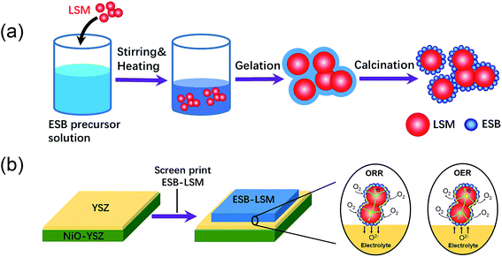
:![[thin space (1/6-em)]](https://www.rsc.org/images/entities/char_2009.gif) 1. The resultant black LSM powder was calcined at 900 °C in air for 2 h. Er0.4Bi1.6O3 (ESB) decorated LSM powder with 40 wt% ESB and 60 wt% LSM was synthesized by the gelation process. In this process, an ESB aqueous precursor solution consisting of Er(NiO3)3 (Er(NiO3)3·5H2O, 99.9%, Sigma-Aldrich), Bi(NO3)3 (Bi(NO3)3·5H2O, 98%, Sigma-Aldrich), citric acid, EDTA and ammonia solution was stirred on a hotplate for 2 h. Subsequently the LSM powder was added to the solution and stirred continuously until the occurrence of gelation. The gel was thoroughly dried in an oven at 180 °C for 8 h and calcined at 600 °C in air for 2 h, forming ESB decorated LSM powder. The ESB decorated LSM powder was denoted as ESB–LSM. For the purpose of phase identification, the ESB powder was also synthesized using a modified Pechini method and sintered at 600 °C for 2 h. Er doping can stabilize the cubic structure of δ-Bi2O3 in a wider temperature region and it has been reported that ESB remains cubic at temperatures as low as 500 °C.39 Therefore, in the testing temperature range of 500–750 °C, ESB would adopt the cubic structure without undergoing structural and volume changes. The addition of Er will also increase the melting temperature of Bi2O3 up to 1100 °C,39 thus reducing the volatility of bismuth.
1. The resultant black LSM powder was calcined at 900 °C in air for 2 h. Er0.4Bi1.6O3 (ESB) decorated LSM powder with 40 wt% ESB and 60 wt% LSM was synthesized by the gelation process. In this process, an ESB aqueous precursor solution consisting of Er(NiO3)3 (Er(NiO3)3·5H2O, 99.9%, Sigma-Aldrich), Bi(NO3)3 (Bi(NO3)3·5H2O, 98%, Sigma-Aldrich), citric acid, EDTA and ammonia solution was stirred on a hotplate for 2 h. Subsequently the LSM powder was added to the solution and stirred continuously until the occurrence of gelation. The gel was thoroughly dried in an oven at 180 °C for 8 h and calcined at 600 °C in air for 2 h, forming ESB decorated LSM powder. The ESB decorated LSM powder was denoted as ESB–LSM. For the purpose of phase identification, the ESB powder was also synthesized using a modified Pechini method and sintered at 600 °C for 2 h. Er doping can stabilize the cubic structure of δ-Bi2O3 in a wider temperature region and it has been reported that ESB remains cubic at temperatures as low as 500 °C.39 Therefore, in the testing temperature range of 500–750 °C, ESB would adopt the cubic structure without undergoing structural and volume changes. The addition of Er will also increase the melting temperature of Bi2O3 up to 1100 °C,39 thus reducing the volatility of bismuth.
The as-prepared ESB–LSM powder was thoroughly blended with an ink vehicle (Fuel Cell Materials) at a weight ratio of 7![[thin space (1/6-em)]](https://www.rsc.org/images/entities/char_2009.gif) :
:![[thin space (1/6-em)]](https://www.rsc.org/images/entities/char_2009.gif) 3 in a mortar. The ink was screen-printed on the YSZ electrolyte surface of the Ni–YSZ anode supported cell and dried at 100 °C for 2 h to form the directly assembled oxygen electrode without further pre-sintering at high temperatures. The direct assembly bypasses the high temperature sintering steps and avoids the melting issues associated with the use of bismuth oxides. Fig. 1 shows the schematic of synthesis and direct assembly of the ESB–LSM oxygen electrode on a barrier-layer-free YSZ electrolyte cell.
3 in a mortar. The ink was screen-printed on the YSZ electrolyte surface of the Ni–YSZ anode supported cell and dried at 100 °C for 2 h to form the directly assembled oxygen electrode without further pre-sintering at high temperatures. The direct assembly bypasses the high temperature sintering steps and avoids the melting issues associated with the use of bismuth oxides. Fig. 1 shows the schematic of synthesis and direct assembly of the ESB–LSM oxygen electrode on a barrier-layer-free YSZ electrolyte cell.
The geometric area of the oxygen electrode was 0.25 cm2 with a thickness of 30–40 μm. Pt ink (Gwent Electronic Materials Ltd) was painted on the electrodes as the current collector and heat-treated at 150 °C for 2 h. Similarly, LSM and LSM–YSZ with a weight ratio of 6![[thin space (1/6-em)]](https://www.rsc.org/images/entities/char_2009.gif) :
:![[thin space (1/6-em)]](https://www.rsc.org/images/entities/char_2009.gif) 4 composite oxygen electrodes were also directly assembled on a YSZ electrolyte cell and tested under identical conditions.
4 composite oxygen electrodes were also directly assembled on a YSZ electrolyte cell and tested under identical conditions.
2.2 Electrochemical tests
For testing in fuel cell mode, hydrogen at a flow rate of 50 ml min−1 was supplied to the hydrogen electrode, while H2O + H2 or CO2 + H2 at a total flow rate of 50 ml min−1 was used for testing in electrolysis or reversible mode. The oxygen electrode was exposed to static surrounding air. The Ni–YSZ hydrogen electrode was reduced in hydrogen at 750 °C for 1 h prior to the performance evaluation. Electrochemical polarization and impedance curves were measured in a temperature range of 500–750 °C, using a Gamry Reference 3000 Potentiostat. The impedance spectra were obtained in a frequency range of 100 kHz to 0.1 Hz with a signal amplitude of 10 mV at open circuit. The cell ohmic resistance, RΩ, was obtained from the high frequency intercept of impedance spectra and the electrode polarization resistance, Rp, was obtained from the difference between the low and high frequency intercepts. To evaluate the cell stability, the cell voltage was recorded in fuel cell, electrolysis or reversible mode at a constant current of 500 mA cm−2 at 750 °C or 650 °C.2.3 Characterization
The phases of the as-synthesized powders were identified by X-ray diffraction (XRD) using a Bruker D8 Advance X-ray diffractometer with a Cu Kα X-ray source. The powders were also dispersed in isopropanol using ultrasound treatment, loaded on copper grids and characterized with a Zeiss Neon 40EsB scanning electron microscope (SEM) and a high angle annular dark field scanning transmission electron microscope (HAADF-STEM, FEI Titan G2 80-200 TEM/STEM with ChemiSTEM Technology) at 200 kV. To investigate the electrode/electrolyte interface, a lamella was prepared on the ESB–LSM/YSZ cross-section region using an FEI Helios Nanolab G3 CX DualBeam focused ion beam (FIB)-SEM. Microstructural observation and elemental mapping analysis of the lamella were performed using the aforementioned HAADF-STEM. The microstructure of the cells was also examined by SEM. In some cases, the oxygen electrodes were removed from the YSZ surface by acid treatment in 32% HCl solution at room temperature for 24 h.3. Results and discussion
3.1 Microstructure and phase of the ESB–LSM cathode
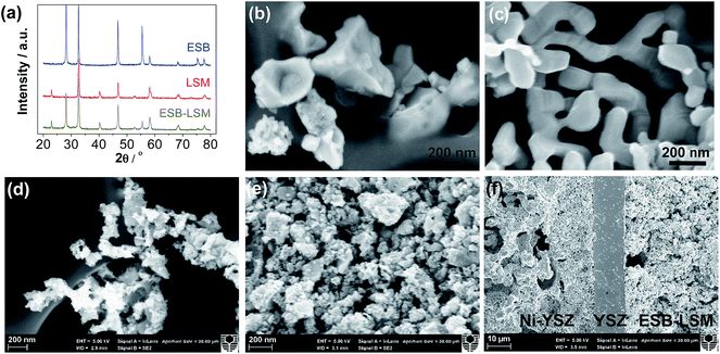
Fig. 2 shows the XRD patterns and SEM micrographs of the as-prepared powders and cross-section of cells with the directly assembled ESB–LSM oxygen electrode. The XRD patterns of ESB powders were consistent with those of cubic ESB (Fig. 2a).39 For the ESB–LSM composite powder, the diffraction peaks can be assigned to the ESB and LSM phases and there are no additional peaks (Fig. 2a). This indicates the formation of the ESB phase at 600 °C and no chemical reactions occurred during the synthesis and calcination of the composite powder, which is advantageous and avoids the formation of impurity phases as in the case of the co-synthesis process.33,45 ESB and LSM in the composite powder remained chemically compatible even after heat-treatment at 750 °C for 110 h (Fig. S1, ESI†).The ESB powder showed irregular shapes with an average particle size of 449 ± 182 nm (Fig. 2b). LSM powder has a smooth surface and the average particle size was 198 ± 54 nm (Fig. 2c). In the case of ESB–LSM, the powder is characterized by a very fine and highly porous structure and the particle size of the ESB–LSM composite is much smaller as compared to the separately prepared ESB and LSM powders (Fig. 2d). This indicates that the decoration process via gelation inhibits the agglomeration and growth of both ESB and LSM particles. The directly assembled ESB–LSM electrode showed a fine and porous structure despite the high ESB loading of 40 wt% (Fig. 2e), which is also different from that of the directly assembled ESB/LSM electrode prepared by direct mixing (Fig. S2, ESI†). The decoration approach avoids multiple infiltration/heat-treatment processes and therefore is much faster and more effective as compared to the conventional wet infiltration processes.35,36,52 The ESB–LSM electrode maintained fine and nanostructure characteristics even after heat-treatment at 750 °C in air for 110 h (Fig. S3, ESI†), indicating that the decorated structure has an excellent ability to resist thermal ripening. The oxygen electrode adhered well to the YSZ electrolyte film after the electrochemical and stability tests (Fig. 2f).
The elemental distribution of ESB–LSM powder was studied by EDS elemental mapping, as shown in Fig. 3. Bismuth oxide was uniformly deposited on the surface of LSM particles but also occupied the voids between LSM particles. The coverage of LSM by decorated ESB would inhibit the grain growth of LSM, consistent with the SEM observations. Therefore, the fine ESB layer decorated LSM structure would produce a large amount of ESB/LSM interfaces for the oxygen reduction/oxidation reactions (ORR/OER). In addition, the incorporation of ESB with high ionic conductivity would also form an ion-conducting network, extending the reaction site from the electrode/electrolyte interface to the bulk of the electrode.
3.2 Performance and stability of directly assembled ESB–LSM cathodes
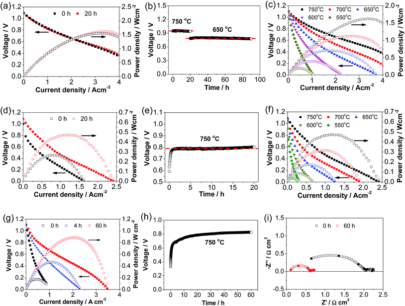
Fig. 4 shows the performance and stability of Ni–YSZ cermet-supported YSZ electrolyte cells with directly assembled ESB–LSM, pristine LSM and LSM–YSZ composite oxygen electrodes. The initial peak power density (PPD) of the cell with a ESB–LSM electrode was 1.55 W cm−2 and increased slightly to 1.62 W cm−2 after polarization at 500 mA cm−2 and 750 °C for 20 h (Fig. 4a). The change of the cell performance with the polarization is very small and the cell voltage is very stable under a constant current of 500 mA cm−2 at 750 °C for 20 h and 650 °C for 70 h (Fig. 4b). This is in good agreement with the observation that the cell impedance spectra were almost unchanged after the stability test (Fig. S4, ESI†). The high power output and insensitivity of the performance with the polarization current passage may indicate the instantaneous formation of an intimate electrode/electrolyte interface in the case of the directly assembled ESB–LSM oxygen electrode.In the case of the directly assembled pristine LSM electrode, the cell performance was enhanced by the polarization (see Fig. 4d). The initial PPD was 0.27 W cm−2 and increased to 0.48 W cm−2 after polarization at 500 mA cm−2 and 750 °C for 20 h (Fig. 4d). The cell voltage at 500 mA cm−2 increased rapidly from 0.59 V to 0.78 V after polarization for 1 h and was almost stable with the further polarization (Fig. 4e). The polarization and stability behavior of the cell with the LSM–YSZ composite oxygen electrode is very similar to that of the LSM electrode (Fig. 4g and h). The initial PPD was 0.17 W cm−2 and increased significantly to 0.42 and 0.88 W cm−2 after polarization at 500 mA cm−2 and 750 °C for 4 and 60 h, respectively (Fig. 4g). The increase in performance corresponds to the decrease in cell RΩ from 0.63 Ω cm2 to 0.10 Ω cm2 and cell Rp from 1.67 Ω cm2 to 0.67 Ω cm2 after polarization for 60 h (Fig. 4i). The significant increase of the PPD and cell voltage in the case of pristine LSM and LSM–YSZ composite electrodes is due to the promoting effect of polarization current on the in situ formation of the electrode/electrolyte interface.48
After the polarization at 750 °C for 20 h, the polarization curves with the pristine LSM and ESB–LSM electrodes were obtained at different temperatures. In the case of the ESB–LSM electrode, the PPDs are 1.62, 1.12, 0.71, 0.40 and 0.20 W cm−2 at 750, 700, 650, 600 and 550 °C, respectively (Fig. 4c), significantly higher than 0.48, 0.32, 0.17, 0.09 and 0.04 W cm−2 of the cell with the pristine LSM electrode (Fig. 4f). The PPD with the ESB–LSM electrode is also significantly higher than 0.88 W cm−2 of the cell with the directly assembled LSM–YSZ composite electrode at 750 °C. The PPD versus the reciprocal temperature gave an activation energy of 74 ± 3 kJ mol−1 for the cell with the ESB–LSM electrode, lower than 83 ± 3 kJ mol−1 for the cell with the pristine LSM electrode (Fig. S5, ESI†). As the YSZ electrolyte and Ni–YSZ anode are the same in both cells, the reduction in the cell power density activation energy would be mainly contributed by the cathode. This demonstrates the effectiveness of ESB decoration in enhancing the electrocatalytic activity of the ORR and lowering the activation energy on the LSM electrode.
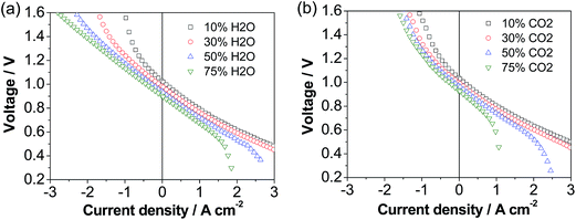
The cell was also investigated in both fuel cell and electrolysis modes in H2–H2O and H2–CO2 atmospheres and the results are shown in Fig. 5. The fuel cell performance decreases with the increase in the concentration of H2O and in particular CO2, while the electrolysis performance is enhanced with increasing the concentration of CO2 and in particular H2O, consistent with previous studies.53 This implies the type of reactant and its concentration have a dramatic effect on the cell performance. Under 50% H2O/50% H2 and 50% CO2/50% H2, the cell voltage was 1.05 and 1.10 V at a current density of 0.5 A cm−2, respectively, and increased to 1.31 and 1.61 V at a current density of 1.5 A cm−2, respectively. This implies that at low current densities the electrolysis performance in H2O and CO2 is similar, but at high current densities the electrolysis performance in H2O is much better than that in CO2. The higher performance of H2O electrolysis than that of CO2 electrolysis is due to the fast adsorption and dissociation processes and high diffusion coefficient of steam.54,55
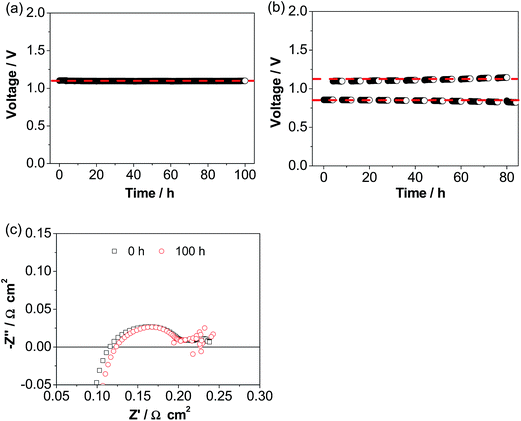
Fig. 6a shows the operational stability of a cell with the ESB–LSM electrode in CO2 electrolysis mode in CO2/H2. The cell voltage was very stable at ∼1.1 V during the continuous electrolysis at 500 mA cm−2 and 750 °C for 100 h, very different from the substantial decay of conventional pre-sintered LSM electrodes and LSM–YSZ composite electrodes.56–61 The excellent stability is supported by the cell impedance responses (Fig. 6c). Cell RΩ and Rp were 0.12 and 0.11 Ω cm2, respectively, after electrolysis at 500 mA cm−2 and 750 °C in H2/CO2 for 100 h, almost the same as the initial 0.11 and 0.12 Ω cm2, respectively, before electrolysis. This indicates the very stable electrode/electrolyte interface of the directly assembled ESB–LSM/YSZ cells in electrolysis mode. This is in contrast to the significant loss of electrolysis performance due to chemical and structural instability such as Sr surface segregation and its transport across the porous GDC layer to form resistive SrZrO3 on the YSZ surface in the case of the LSCF electrode62–65 as well as delamination of the La0.6Sr0.4CoO3−δ–GDC electrode and the Ba0.5Sr0.5Co0.8Fe0.2O3−δ electrode.66–68 The operational stability is also significantly better than that of the cell with a directly assembled LSM–YSZ composite electrode under identical electrolysis conditions (Fig. S6, ESI†). In the case of the cell with a LSM–YSZ composite oxygen electrode, the initial cell voltage was 1.34 V and increased rapidly to 1.62 V after electrolysis at 500 mA cm−2 and 750 °C for 60 h in CO2/H2. The cell was also investigated in reversible cycling of 4 h in fuel cell mode and 4 h in electrolysis mode (Fig. 6b). No performance degradation was observed and excellent stability was obtained during the operation at 500 mA cm−2 and 750 °C for ∼10 cycles.
3.3 ESB–LSM/YSZ interface
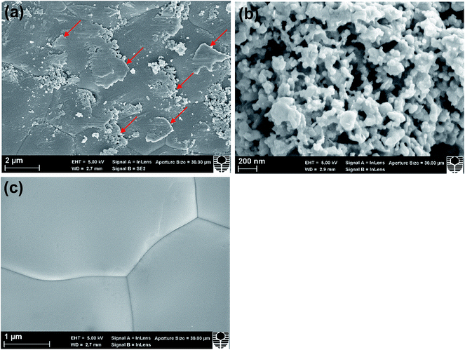
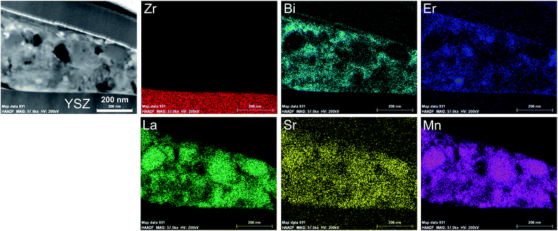
Fig. 7 shows the YSZ surface in contact with the ESB–LSM electrode after the electrochemical stability test. The electrode was peeled off using an adhesive tape. There are a large number of plate-like flat particles adhered on the YSZ surface (indicated by the arrows, Fig. 7a). This plate-like structure appears to be different from the grain-shaped porous structure of the electrode (Fig. 7b), indicating that the formation of such a plate-like particle layer mainly occurs in the electrode/electrolyte interfacial region. The YSZ electrolyte surface after the HCl treatment is very clean and shows no contact marks as in the case of the directly assembled pristine LSM electrode (Fig. 7c).48 This indicates that the plate-like particles/agglomerates can be completely removed from the YSZ electrolyte by HCl acid treatment. The clean YSZ electrolyte surface after the removal of the ESB–LSM electrode also indicates that ESB–LSM would not react with YSZ at 750 °C under the conditions of this study because once the lanthanum or strontium zirconate phase is formed on YSZ, they cannot be removed by simple HCl treatment.69,70To identify the composition of the thin layer on the YSZ electrolyte, a lamella was prepared using FIB-SEM and the STEM-EDS maps are shown in Fig. 8 (see Fig. S7, ESI†). The plate-like flat particle had a thickness of 290 ± 80 nm. The elemental maps indicate that the flat particle consisted of elements of both LSM and ESB. Considering the gelation process of pre-formed LSM particles with ESB gel, it is most likely that LSM particles are encapsulated by the ESB network. This morphology is consistent with the ESB–LSM structure of the as-prepared powder (see Fig. 3). The plate-like flat particles at the electrode/electrolyte interface act as a bridge to firmly adhere the ESB–LSM electrode to the YSZ electrolyte, forming an intimate contact/interface between the ESB–LSM electrode and the YSZ electrolyte. The presence of the highly ion conducting ESB network at the interface not only facilitates rapid ion migration at the electrode/electrolyte interface but also enhances the electrocatalytic activity of the oxygen electrodes.28
Lee et al. studied the performance of the co-synthesized ESB/LSM composite electrode and observed the presence of a 50 nm ESB layer between the YSZ electrolyte and the pre-sintered ESB/LSM composite electrode most likely due to the high wettability and great mobility of ESB on the YSZ electrolyte as a result of its low melting temperature.32 The high wettability of bismuth oxide on YSZ is also supported by the reported uniform distribution of bismuth oxide along the grain boundary of YSZ pellets when using bismuth oxide as a wetting or sintering agent.71,72 In the present study, the formation of the thin bismuth oxide/LSM layer at the interface implies that the low melting temperature and good wettability of ESB are beneficial and facilitate the formation of an intimate contact at the electrode/electrolyte interface of the directly assembled ESB–LSM electrodes. The instantaneously formed electrode/electrolyte interface appears to be supported by the excellent power output and much less sensitivity of the polarization performance under the influence of polarization current, in comparison with directly assembled LSM and LSM–YSZ composite electrodes on YSZ electrolyte cells.46,48
4. Conclusions
ESB–LSM nanostructured powder has been successfully prepared by a simple and effective gelation approach and applied to a Ni–YSZ electrode supported YSZ electrolyte cell via a direct assembly approach bypassing the conventional high temperature pre-sintering process. The cell with the ESB–LSM oxygen electrode exhibits peak power densities of 1.62, 1.12, 0.71, 0.40 and 0.20 W cm−2 at 750, 700, 650, 600 and 550 °C, respectively, substantially higher than 0.48, 0.32, 0.17, 0.09 and 0.04 W cm−2 obtained on the cell with the pristine LSM electrode. The cell also shows remarkable durability at 500 mA cm−2 and 750 °C in fuel cell, electrolysis and reversible SOC modes for over 200 h. The high electrode activity and stability are most likely due to the highly active ESB–LSM oxygen electrode for the ORR/OER as well as the instantaneously formed ESB–LSM electrode/YSZ electrolyte interface for the rapid oxygen ion migration at the interface. The high wettability and softening properties of the ESB phase could be responsible for the excellent activity and stability of the instantaneously formed interface though the underlying mechanism requires further investigation. The present study demonstrates the feasibility and excellent opportunities for the development of bismuth oxide based oxygen electrodes for highly active and durable SOCs for efficient energy storage and conversion.Acknowledgements
The work was supported by the Fuzhou University Qishan Scholarship Program (No. XRC-17010), National Natural Science Foundation of China (No. 51672045), and Australian Research Council under the Discovery Project Scheme (Project No. DP150102044 and DP150102025). The authors acknowledge the facilities, scientific and technical assistance of the Curtin University Microscopy & Microanalysis Facility and the Australian Microscopy & Microanalysis Research Facility at the Centre for Microscopy, Characterisation & Analysis, The University of Western Australia, both of which are partially funded by the University, State and Commonwealth Governments.References
- D. M. Bierschenk, J. R. Wilson and S. A. Barnett, Energy Environ. Sci., 2011, 4, 944–951 CAS.
- S. P. Jiang, Asia-Pac. J. Chem. Eng., 2016, 11, 386–391 CrossRef CAS.
- S. H. Jensen, C. Graves, M. Mogensen, C. Wendel, R. Braun, G. Hughes, Z. Gao and S. A. Barnett, Energy Environ. Sci., 2015, 8, 2471–2479 CAS.
- X. M. Ge, L. Zhang, Y. N. Fang, J. Zeng and S. H. Chan, RSC Adv., 2011, 1, 715–724 RSC.
- J. H. Myung, D. Neagu, D. N. Miller and J. T. S. Irvine, Nature, 2016, 537, 528–531 CrossRef CAS PubMed.
- J. R. Mawdsley, J. D. Carter, A. J. Kropf, B. Yildiz and V. A. Maroni, Int. J. Hydrogen Energy, 2009, 34, 4198–4207 CrossRef CAS.
- G. A. Hughes, K. Yakal-Kremski and S. A. Barnett, Phys. Chem. Chem. Phys., 2013, 15, 17257–17262 RSC.
- K. Chen and S. P. Jiang, J. Electrochem. Soc., 2016, 163, F3070–F3083 CrossRef.
- J. T. S. Irvine, D. Neagu, M. C. Verbraeken, C. Chatzichristodoulou, C. Graves and M. B. Mogensen, Nat. Energy, 2016, 1, 15014 CrossRef CAS.
- C. Graves, S. D. Ebbesen, S. H. Jensen, S. B. Simonsen and M. B. Mogensen, Nat. Mater., 2015, 14, 239–244 CrossRef CAS PubMed.
- M. S. Sohal, J. E. O'Brien, C. M. Stoots, V. I. Sharma, B. Yildiz and A. Virkar, J. Fuel Cell Sci. Technol., 2012, 9, 11017 CrossRef.
- C. H. Yang, C. Jin, A. Coffin and F. L. Chen, Int. J. Hydrogen Energy, 2010, 35, 5187–5193 CrossRef CAS.
- M. B. Choi, B. Singh, E. D. Wachsman and S. J. Song, J. Power Sources, 2013, 239, 361–373 CrossRef CAS.
- X. F. Sun, M. Chen, Y. L. Liu, P. Hjalmarsson, S. D. Ebbesen, S. H. Jensen, M. B. Mogensen and P. V. Hendriksen, J. Electrochem. Soc., 2013, 160, F1074–F1080 CrossRef CAS.
- N. Ai, K. Chen, S. Liu and S. P. Jiang, Int. J. Hydrogen Energy, 2013, 38, 16569–16578 CrossRef CAS.
- K. F. Chen, N. Ai and S. P. Jiang, J. Electrochem. Soc., 2010, 157, P89–P94 CrossRef CAS.
- K. Chen, N. Ai and S. P. Jiang, Int. J. Hydrogen Energy, 2012, 37, 1301–1310 CrossRef CAS.
- K. Chen, N. Ai and S. P. Jiang, Electrochem. Commun., 2012, 19, 119–122 CrossRef CAS.
- K. Chen, N. Ai and S. P. Jiang, Int. J. Hydrogen Energy, 2014, 39, 10349–10358 CrossRef CAS.
- M. D. Liang, B. Yu, M. F. Wen, J. Chen, J. M. Xu and Y. C. Zhai, J. Power Sources, 2009, 190, 341–345 CrossRef CAS.
- Q. Su, D. Yoon, Z. Sisman, F. Khatkhatay, Q. Jia, A. Manthiram and H. Wang, Int. J. Hydrogen Energy, 2013, 38, 16320–16327 CrossRef CAS.
- C. H. Yang, A. Coffin and F. L. Chen, Int. J. Hydrogen Energy, 2010, 35, 3221–3226 CrossRef CAS.
- N. M. Sammes, G. A. Tompsett, H. Nafe and F. Aldinger, J. Eur. Ceram. Soc., 1999, 19, 1801–1826 CrossRef CAS.
- P. Shuk, H. D. Wiemhofer, U. Guth, W. Gopel and M. Greenblatt, Solid State Ionics, 1996, 89, 179–196 CrossRef CAS.
- B. Singh, S. Ghosh, S. Aich and B. Roy, J. Power Sources, 2017, 339, 103–135 CrossRef CAS.
- E. D. Wachsman and K. T. Lee, Science, 2011, 334, 935–939 CrossRef CAS PubMed.
- K. T. Lee, H. S. Yoon and E. D. Wachsman, J. Mater. Res., 2012, 27, 2063–2078 CrossRef CAS.
- K. T. Lee, D. W. Jung, H. S. Yoon, A. A. Lidie, M. A. Camaratta and E. D. Wachsman, J. Power Sources, 2012, 220, 324–330 CrossRef CAS.
- J. Li, S. Wang, R. Liu, T. Wen and Z. Wen, Fuel Cells, 2009, 9, 657–662 CrossRef CAS.
- J. Hou, L. Bi, J. Qian, Z. Gong, Z. Zhu and W. Liu, J. Power Sources, 2016, 301, 306–311 CrossRef CAS.
- J. Li, S. Wang, X. Sun, R. Liu, X. Ye and Z. Wen, J. Power Sources, 2008, 185, 649–655 CrossRef CAS.
- K. T. Lee, A. A. Lidie, H. S. Yoon and E. D. Wachsman, Angew. Chem., 2014, 126, 13681–13685 CrossRef.
- J. Yan, Z. Zhao, L. Shang, D. Ou and M. Cheng, J. Power Sources, 2016, 319, 124–130 CrossRef CAS.
- Z. Y. Jiang, C. R. Xia, F. Zhao and F. L. Chen, Electrochem. Solid-State Lett., 2009, 12, B91–B93 CrossRef CAS.
- Z. Y. Jiang, L. Zhang, L. L. Cai and C. R. Xia, Electrochim. Acta, 2009, 54, 3059–3065 CrossRef CAS.
- J. Li, S. Wang, Z. Wang, R. Liu, T. Wen and Z. Wen, J. Power Sources, 2009, 194, 625–630 CrossRef CAS.
- D. W. Jung, K. L. Duncan and E. D. Wachsman, Acta Mater., 2010, 58, 355–363 CrossRef CAS.
- A. M. Azad, S. Larose and S. A. Akbar, J. Mater. Sci., 1994, 29, 4135–4151 CrossRef CAS.
- N. Jiang and E. D. Wachsman, J. Am. Ceram. Soc., 1999, 82, 3057–3064 CrossRef CAS.
- J. W. Medernach and R. L. Snyder, J. Am. Ceram. Soc., 1978, 61, 494–497 CrossRef CAS.
- Z. P. Shao and S. M. Haile, Nature, 2004, 431, 170–173 CrossRef CAS PubMed.
- N. Ai, S. P. Jiang, Z. Lu, K. F. Chen and W. H. Su, J. Electrochem. Soc., 2010, 157, B1033–B1039 CrossRef CAS.
- M. E. Lynch, L. Yang, W. T. Qin, J. J. Choi, M. F. Liu, K. Blinn and M. L. Liu, Energy Environ. Sci., 2011, 4, 2249–2258 CAS.
- V. Esposito, E. Traversa and E. D. Wachsman, J. Electrochem. Soc., 2005, 152, A2300–A2305 CrossRef CAS.
- A. Chakraborty and H. S. Maiti, Ceram. Int., 1999, 25, 115–123 CrossRef CAS.
- S. P. Jiang, J. Electrochem. Soc., 2015, 162, F1119–F1128 CrossRef CAS.
- M. Li, K. Chen, B. Hua, J.-l. Luo, W. D. A. Rickard, J. Li, J. T. S. Irvine and S. P. Jiang, J. Mater. Chem. A, 2016, 4, 19019–19025 CAS.
- N. Li, N. Ai, K. Chen, Y. Cheng, S. He, M. Saunders, A. Dodd, A. Suvorova and S. P. Jiang, RSC Adv., 2016, 6, 99211–99219 RSC.
- K. Chen, N. Li, N. Ai, M. Li, Y. Cheng, W. D. A. Rickard, J. Li and S. P. Jiang, J. Mater. Chem. A, 2016, 4, 17678–17685 CAS.
- K. F. Chen, N. Li, N. Ai, Y. Cheng, W. D. A. Rickard and S. P. Jiang, ACS Appl. Mater. Interfaces, 2016, 8, 31729–31737 CAS.
- K. F. Chen, Z. Lu, N. Ai, X. Q. Huang, Y. H. Zhang, X. D. Ge, X. S. Xin, X. J. Chen and W. H. Su, Solid State Ionics, 2007, 177, 3455–3460 CrossRef CAS.
- S. P. Jiang, Int. J. Hydrogen Energy, 2012, 37, 449–470 CrossRef CAS.
- W. P. Pan, K. F. Chen, N. Ai, Z. Lu and S. P. Jiang, J. Electrochem. Soc., 2016, 163, F106–F114 CrossRef CAS.
- Z. Zhan, W. Kobsiriphat, J. R. Wilson, M. Pillai, I. Kim and S. A. Barnett, Energy Fuels, 2009, 23, 3089–3096 CrossRef CAS.
- Y. Li, P. Li, B. Hu and C. Xia, J. Mater. Chem. A, 2016, 4, 9236–9243 CAS.
- R. Knibbe, M. L. Traulsen, A. Hauch, S. D. Ebbesen and M. Mogensen, J. Electrochem. Soc., 2010, 157, B1209–B1217 CrossRef CAS.
- M. A. Laguna-Bercero, R. Campana, A. Larrea, J. A. Kilner and V. M. Orera, J. Power Sources, 2011, 196, 8942–8947 CrossRef CAS.
- C. Graves, S. D. Ebbesen and M. Mogensen, Solid State Ionics, 2011, 192, 398–403 CrossRef CAS.
- K. F. Chen and S. P. Jiang, Int. J. Hydrogen Energy, 2011, 36, 10541–10549 CrossRef CAS.
- K. Chen, N. Ai and S. P. Jiang, Int. J. Hydrogen Energy, 2012, 37, 10517–10525 CrossRef CAS.
- M. Keane, M. K. Mahapatra, A. Verma and P. Singh, Int. J. Hydrogen Energy, 2012, 37, 16776–16785 CrossRef CAS.
- E. Lay-Grindler, J. Laurencin, J. Villanova, I. Kieffer, F. Usseglio-Viretta, T. Le Bihan, P. Bleuet, A. Mansuy and G. Delette, in Solid Oxide Fuel Cells 13, ed. T. Kawada and S. C. Singhal, 2013, vol. 57, pp. 3177–3187 Search PubMed.
- J. Schefold, A. Brisse and F. Tietz, J. Electrochem. Soc., 2012, 159, A137–A144 CrossRef CAS.
- F. Tietz, D. Sebold, A. Brisse and J. Schefold, J. Power Sources, 2013, 223, 129–135 CrossRef CAS.
- D. The, S. Grieshammer, M. Schroeder, M. Martin, M. Al Daroukh, F. Tietz, J. Schefold and A. Brisse, J. Power Sources, 2015, 275, 901–911 CrossRef CAS.
- H. Fan, M. Keane, P. Singh and M. Han, J. Power Sources, 2014, 268, 634–639 CrossRef CAS.
- Y. F. Zheng, Q. S. Li, T. Chen, W. Wu, C. Xu and W. G. Wang, Int. J. Hydrogen Energy, 2015, 40, 2460–2472 CrossRef CAS.
- P. Kim-Lohsoontorn, D. J. L. Brett, N. Laosiripojana, Y. M. Kim and J. M. Bae, Int. J. Hydrogen Energy, 2010, 35, 3958–3966 CrossRef CAS.
- S. P. Jiang, J. P. Zhang, Y. Ramprakash, D. Milosevic and K. Wilshier, J. Mater. Sci., 2000, 35, 2735–2741 CrossRef CAS.
- A. Mitterdorfer and L. J. Gauckler, Solid State Ionics, 1998, 111, 185–218 CrossRef CAS.
- T. H. Yeh, G. E. Kusuma, M. B. Suresh and C. C. Chou, Mater. Res. Bull., 2010, 45, 318–323 CrossRef CAS.
- D. W. Joh, J. H. Park, D. Y. Kim, B.-H. Yun and K. T. Lee, J. Power Sources, 2016, 320, 267–273 CrossRef CAS.
Footnote |
| † Electronic supplementary information (ESI) available. See DOI: 10.1039/c7ta02950k |
| This journal is © The Royal Society of Chemistry 2017 |

