Research highlights
Yassen
Abbas
abc,
Mark W.
Tibbitt
d,
Mehmet R.
Dokmeci
ab and
Ali
Khademhosseini
*abef
aCenter for Biomedical Engineering, Department of Medicine, Brigham and Women’s Hospital, Harvard Medical School, Cambridge, Massachusetts 02139, USA. E-mail: alik@rics.bwh.harvard.edu
bHarvard-MIT Division of Health Sciences and Technology, Massachusetts Institute of Technology, Cambridge, Massachusetts 02139, USA
cSchool of Engineering, University of Edinburgh, Edinburgh, EH9 3JL, UK
dDepartment of Chemical and Biological Engineering, University of Colorado, Boulder, Colorado 80303, USA
eWyss Institute for Biologically Inspired Engineering, Harvard University, Boston, Massachusetts 02115, USA
fWorld Premier International – Advanced Institute for Materials Research (WPI-AIMR), Tohoku University, Sendai 980-8577, Japan
First published on 21st February 2013
Self-directed 3D angiogenesis
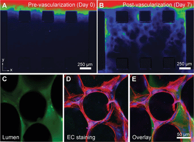
Engineering of thick tissue constructs is often required in regenerative medicine applications. While building these thick tissue constructs, a complex vasculature is needed to deliver oxygen and nutrients to cells. One of the strategies for stimulating the growth of new blood vessels (angiogenesis) within these constructs includes the insertion of angiogenic growth factors into the scaffolds. In recent years microfluidics has also been utilized to study the effect of continuous release of growth factors on angiogenic sprouting.1 For example, microvessels made of collagen gels were used to demonstrate angiogenesis in vitro.2 Despite the potential these systems have for improving our fundamental understanding of angiogenesis, they lack the full physiological structure of blood vessels in the body. Furthermore, in most cases the microengineered vessels are single layer structures, which limits the random sprouting of new capillaries in multiple spatial planes.In an attempt to address this limitation and stimulate 3D angiogenic sprouting, Kamm and colleagues3 utilized a microfluidic platform and embedded alginate microbeads inside a collagen matrix. The purpose of the beads was to form the 3D architecture of the capillary bed. In their work Chan et al.3 demonstrated two methods which enhanced angiogenesis from human microvascular endothelial cells. These included the addition of a high concentration of growth factors into the cell media and the encapsulation of cell lines that secreted growth factors. The microfluidic device used in this study had the standard structure for vessel sprouting experiments: two linear parallel microfluidic channels connected with a 1.25 mm wide block of collagen gel, such that liquids could diffuse through the gel from one channel to the other. The gel contained either empty alginate beads or cell-containing beads (150 μm diameter) that were formed off-chip using a focused air-jet stream. In addition, the edge of the gel was supported by multiple PDMS posts (Fig. 1 A, B); this geometry was chosen to facilitate angiogenic sprouting.
 | ||
| Fig. 1 Representative images of media flow (containing tracking particles) through the capillary gel bed over 7 days of culture (A, B). The flow improved over time due to the presence of angiogenic sprouts. The lumen of the formed capillaries is shown in C–E. Figure reprinted with permission from Chan et al.3 | ||
An external supply of growth factors was introduced through the microfluidic channels and aided angiogenic sprouting, in line with previous research in the field.2 As predicted by the authors the spherical shape and greater stiffness of the alginate beads stimulated the growth of capillaries in the z-direction (perpendicular to the plane of the device). Interestingly, the extent of angiogenic sprouting could be controlled by the presence or absence of alginate beads in the collagen solution. Namely, the sprouting of new vessels improved with the addition of suspended alginate beads, while the removal of the beads resulted in only 25% vascularization in the gel bed. This variation has been linked to a change in the gel microenvironment, with the alginate beads making the gel solution stiffer.
Angiogenic sprouting was further demonstrated in a co-culture test of vascular cells with HT-1080 human fibrosarcoma (a malignant tumor) cells, encapsulated within the alginate beads. In this experiment no growth factors were added to the cell medium, yet the size of the newly sprouted vessels was higher than in the single cell culture test. It was suggested that growth factors were readily excreted from the HT-1080 cells, producing on average 100 μm longer sprouts.
The last question posed by the authors was whether the observed localized angiogenic sprouts could join to form a functional vascular network. A monolayer of vascular cells was seeded in one of the microchannels. An exogenous supply of growth factors stimulated angiogenesis, forming 3D capillaries throughout the gel bed. After a 4–5 day culture, capillaries formed across the gel region, forming lumens at all levels within the gel that could be perfused, as demonstrated with a fluorescent dye (Fig. 1 C–E).
The proposed use of microscale alginate beads for self-directed angiogenesis offers the basis for 3D vascularization in future tissue engineering constructs. As a microfluidic platform the capillary gel bed is easy to assemble and manipulate. The next step in this line of research would be to create a flow based model that mimics physiological shear stresses and the cyclic stretch that blood vessels experience in vivo. Ultimately, this may lead to a densely vascularized tissue model that can sustain multiple cell types such as those found in major organs like the heart and liver.
Probing into cells with quantum dots
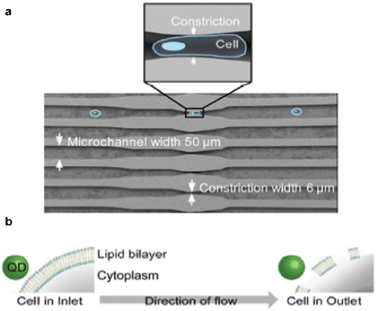
Visual cell analysis using quantum dots (QDs), semiconducting nanoparticles whose electronic properties are dependent on their size and geometry, is emerging as an alternative to fluorescent organic dyes. Compared to the latter, QDs are more photostable and have a broader excitation spectrum. Furthermore, the high emission intensity of QD fluorescence allows for straightforward tracking of single protein molecules, individual DNA or RNA strands, and potentially whole organelles. QD technology has been successfully utilized to mark proteins on the surface of cells. Furthermore, a more interesting application would be to use QDs to probe molecules within cells. Despite progress in recent years with penetration of nanoparticles into the cell membrane,4 high-throughput delivery of QDs into live cells remains a major challenge.In their recent article Bawendi and co-workers describe a novel method for high-throughput delivery of QDs into the cytoplasm of live cells using microfluidics. Lee et al.5 pipetted an aqueous solution containing QDs and HeLa cells into a microfluidic device that was designed to withstand pressures of up to 70 psi. Once inside, the solution flowed through a series of narrow parallel channels where the width of the channels was reduced to 6 μm at the constriction sites (Fig. 2a). The cells were forced to deform as they passed through the constriction sites.6 Once the cells were deformed, their membranes became permeable to nanoparticles. Then, QDs in the solution were able to diffuse through the cell membrane into the cytosol, the fluid constituent of the cell cytoplasm (Fig. 2b). However, this deformation was short lived, allowing QDs a limited time for diffusion. Once the QD entered the cells, the fluorescence signal could be sustained for at least 48 h. Over time the signal intensity was reduced mostly due to cell division.
 | ||
| Fig. 2 QD delivery into live cells. (a) Schematic of the microfluidic device, indicating the constrictions in the narrow microchannels. (b) Schematic of the QD entry into the cells. Figure adapted and reprinted with permission from Lee et al.5 | ||
The authors observed that as the QDs entered the cells they diffused into the cell cytosol rather than being sequestered in the endosomes (membrane bound vesicles of eukaryotic cells). The cytosol contains molecules that could aid the reduction of disulfide bonds in the presence of a redox molecule, glutathione. In comparison, disulfide bonds in the extracellular space or endosomes are preserved due to an oxidizing environment. This difference in the microenvironmental biochemistry was employed to synthesize nanoparticles that could selectively alter their emission profile and only fluoresce inside the reducing cytosolic environment. To achieve this the researchers engineered green light emitting QDs which were conjugated with a disulfide bond to a red fluorescent dye. Outside the reducing cellular environment and upon excitation at a specific wavelength, energy was transferred from the QD to the dye. Upon entering the cytosol the disulfide bond was cleaved, therefore suspending the energy transfer. Hence, inside the redox environment, the green fluorescence signal of the QD dominated. The authors confirmed that the QDs entered the cell cytosol by visualising the change in cell color from red to green using confocal microscopy. Intensity profiles indicated that the bulk change in fluorescence occurred 2–4 h after the cells had been tagged inside the microfluidic device.
Biocompatibility of the process with the cells was achieved through coating of the QDs with a poly(ethylene) glycol-based ligand. The authors reported a cell viability of greater than 80%, measured using flow cytometry, indicating that the cells were compatible with the QDs and that they were also immune to the high shear stresses generated on-chip. The efficiency of labelling cells with QDs was ∼40%, at a rate of ∼10![[thin space (1/6-em)]](https://www.rsc.org/images/entities/char_2009.gif) 000 cells s−1. Although the efficiency may appear a bit low, this process resulted in a large number of labelled cells per second, and sorting methods like fluorescence-activated cell sorting could be employed to separate the labelled cells from the unlabelled ones.
000 cells s−1. Although the efficiency may appear a bit low, this process resulted in a large number of labelled cells per second, and sorting methods like fluorescence-activated cell sorting could be employed to separate the labelled cells from the unlabelled ones.
The reported results iterate the effectiveness of this microfluidic platform to deliver nanoparticles to the cell cytosol. Moreover, the potential applications of a high-throughput system which maintains high cell viability goes beyond bio-imaging. Applications which could benefit from this platform include delivery of therapeutic nanomedicines in the treatment of cancer and nanoparticles which target tissue regeneration.
Fishing for cells: extracting dilute information from whole blood
The fluids that perfuse the human body carry essential nutrients and waste throughout the body to maintain viability and function of the interconnected organs. This fluidic milieu can also transport biomolecules and circulating cells that are often harbingers of pathological tissue; at the same time it can provide an avenue for diagnosis and monitoring of disease as well as drug discovery and screening.7 However, these markers of disease are often extremely rare and difficult to isolate from a dilute stream. Recently, strategies have been presented to isolate circulating tumor cells (CTCs; 1 in 109 hematologic cells) from whole blood using antibodies targeted to cell surface markers, and these platforms are increasingly used in clinical settings.8 Yet, there are still significant limitations to the efficiency and throughput of current capture techniques and few enable the release of isolated cells or biomolecules for subsequent analysis. Thus, an improved strategy with more efficient capture that also enables increased fluid throughput and release of cells would aid in the detection and isolation of cells and biomolecules from the whole blood.Drawing upon inspiration from marine species that feed on dilute nutrients in aqueous environments by collecting them with branched tentacles, Karp and co-workers have recently reported a unique strategy to capture cells from whole blood within a microfluidic device functionalized with long polyvalent DNA chains.9 These polyvalent chains contained multiple repeats of an aptamer (binding molecule) targeted to a specific cell surface receptor and demonstrated enhanced binding ability to cells as compared to single aptamers. Further, the polyvalent DNA brushes penetrated into the fluid flow, like the tentacles of certain marine creatures, and were able to maintain cell adhesion at greater distances from the binding surface and at increased shear stress. Enzymes were subsequently added to the cell–DNA construct to facilely release the bound cells from the device.
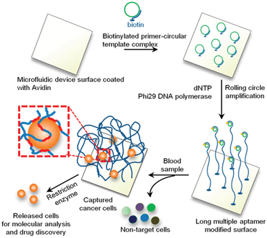
To form the DNA-brush microfluidic capture surfaces, Zhao et al.9 initially coated the device surface with avidin to which a biotinylated primer, encoding the sequence for the target aptamer, was attached (Fig. 3). Rolling circle amplification (RCA) was then employed to amplify the primer multiple times and the extent of polyvalency was tuned by the RCA reaction time. In this work, one aptamer specific to protein tyrosine kinase 7 (PTK7), which is expressed on leukemia, lung cancer, and colon cancer cells, demonstrated the ability to capture PTK7+ cells specifically from both buffer and whole blood when the aptamer sequence was incorporated into the 3D DNA-brush. Capture of PTK7+ cells under flow illustrated the ability of the polyvalent brushes to capture cells at three-fold higher shear stresses as compared to monovalent aptamers, indicating that employing the tentacle-like approach enables the device to process more fluid in a given time. Further, the purity of PTK7+ cells captured by the device from whole blood at low flow rates was nearly 85% whereas current devices capture at a purity of ∼15%. It is important to note that since aptamers are employed in this technique, the capture can be tuned specifically to a broad range of cell types or biomolecules. Finally, DNase I was added to the microfluidic device to release cells from the DNA-brush under flow and the recovered cells remained viable.
 | ||
| Fig. 3 Schematic illustration of the generation of DNA-brush modified microfluidic surfaces for selective cell capture and release. Figure reprinted with permission from Zhao et al.9 | ||
Importantly, the authors extended the DNA-brush approach to more complex device geometries, such as the recently reported10 high-throughput and high-efficiency herringbone microfluidic capture device (HB-chip). At low specific throughput values (0–0.5 ml h−1 cm−2), the RCA-HB-chip achieved similar capture efficiencies as monovalent HB-chips; however, the efficiency of the RCA-HB-chip was improved (2–3×) over these devices at increased specific throughput values (0.5–2.0 ml h−1 cm−2). Ultimately, employing this technique in the HB-chips translated to operating the device with a 10-fold increase in flow rate without sacrificing efficiency while capturing a population of cells with higher purity. Building upon these results, the tentacle-like, polyvalent DNA-brushes should enable better translation of microfluidic devices into the clinical setting for disease diagnosis, monitoring, and therapy.
References
- S. Chung, R. Sudo, V. Vickerman, I. K. Zervantonakis and R. D. Kamm, Ann. Biomed. Eng., 2010, 38, 1164–1177 CrossRef.
- Y. Zheng, J. Chen, M. Craven, N. W. Choi, S. Totorica, A. Diaz-Santana, P. Kermani, B. Hempstead, C. Fischbach-Teschl, J. A. Lopez and A. D. Stroock, Proc. Natl. Acad. Sci. U. S. A., 2012, 109, 9342–9347 CrossRef CAS.
- J. M. Chan, I. K. Zervantonakis, T. Rimchala, W. J. Polacheck, J. Whisler and R. D. Kamm, PLoS One, 2012, 7, e50582 CAS.
- A. Verma, O. Uzun, Y. Hu, Y. Hu, H.-S. Han, N. Watson, S. Chen, D. J. Irvine and F. Stellacci, Nat. Mater., 2008, 7, 588–595 CrossRef CAS.
- J. Lee, A. Sharei, W. Y. Sim, A. Adamo, R. Langer, K. F. Jensen and M. G. Bawendi, Nano Lett., 2012, 12, 6322–6327 CrossRef CAS.
- A. Sharei, J. Zoldan, A. Adamo, W. Y. Sim, N. Cho, E. Jackson, S. Mao, S. Schneider, M.-J. Han, A. Lytton-Jean, P. A. Basto, S Jhunjhunwala, J. Lee, D. A. Heller, J. W. Kang, G. C. Hartoularos, K.-S. Kim, D. G. Anderson, R. Langer and K. F. Jensen, Proc. Natl. Acad. Sci. U. S. A., 2013, 110, 2082–2087 CrossRef.
- K. Pantel, R. H. Brakenhoff and B. Brandt, Nat. Rev. Cancer, 2008, 8, 329–340 CrossRef CAS.
- S. L. Stott, R. J. Lee, S. Nagrath, M. Yu, D. T. Miyamoto, L. Ulkus, E. J. Inserra, M. Ulman, S. Springer, Z. Nakamura, A. L. Moore, D. I. Tsukrov, M. E. Kempner, D. M. Dahl, C. L. Wu, A. J. Iafrate, M. R. Smith, R. G. Tompkins, L. V. Sequist, M. Toner, D. A. Haber and S. Maheswaran, Sci. Transl. Med., 2010, 2, 25ra23 CrossRef.
- W. Zhao, C. H. Cui, S. Bose, D. Guo, C. Shen, W. P. Wong, K. Halvorsen, O. C. Farokhzad, G. S. L. Teo, J. A. Phillips, D. M. Dorfman, R. Karnik and J. M. Karp, Proc. Natl. Acad. Sci. U. S. A., 2012, 109, 21289–21294 CrossRef.
- S. L. Stott, C. H. Hsu, D. I. Tsukrov, M. Yu, D. T. Miyamoto, B. A. Waltman, S. M. Rothenberg, A. M. Shah, M. E. Smas, G. K. Korir, F. P. Floyd, A. J. Gilman, J. B. Lord, D. Winokur, S. Springer, D. Irimia, S. Nagrath, L. V. Sequist, R. J. Lee, K. J. Isselbacher, S. Maheswaran, D. A. Haber and M. Toner, Proc. Natl. Acad. Sci. U. S. A., 2010, 107, 18392–18397 CrossRef CAS.
| This journal is © The Royal Society of Chemistry 2013 |
