
 Open Access Article
 This Open Access Article is licensed under a
 Creative Commons Attribution 3.0 Unported Licence
Electrochemical and spectroscopic characterisation of organic molecules with high positive redox potentials for energy storage in aqueous flow cells†
Christopher G. Cannona,
Peter A. A. Klusener b,
Nigel P. Brandonc and
Anthony R. J. Kucernak*a
b,
Nigel P. Brandonc and
Anthony R. J. Kucernak*a
aDepartment of Chemistry Imperial College London MSRH, White City, London W12 0BZ, UK. E-mail: anthony@imperial.ac.uk
bShell Global Solutions International B.V. Energy Transition Campus Amsterdam, Grasweg 31, 1031 HW Amsterdam, The Netherlands
cDepartment of Earth Science and Engineering Imperial College London South Kensington, London SW7 2AZ, UK
First published on 11th September 2024
Abstract
We show that a number of ubiquitous organic molecules used as redox mediators and chemically sensing species can be used as positive couples in electrochemical energy storage. Air and acid stable organic molecules were tested in aqueous acid electrolytes and employed as the positive electrolyte in H2–organic electrochemical cells. The dissolved organic species were characterised in-operando using UV-vis spectroscopy. N,N,N′,N′-tetramethylbenzidine was found to be a stable and reversible redox organic molecule, with a 2 e− molecule−1 capacity and a 0.83 V cell potential. N-Oxyl species were also tested in purely aqueous acidic flow battery electrolytes. A H2–violuric acid cell produced a reversible potential of 1.16 V and demonstrated promising redox flow cell cycling performance.
1. Introduction
Abundantly available materials that possess multiple oxidation states with long-term stability are greatly sought after to allow for more economically feasible large-scale energy storage devices. Hydrogen is an abundant and proven electrochemical energy storage (EES) medium but pairing it with molecular oxygen on the positive electrode, as in low-temperature H2–O2 polymer electrolyte membrane fuel cells (PEMFCs) and electrolysers (PEMELs), creates many issues. These are mainly related to the material requirements for platinum group metal catalysts, and the relatively poor round-trip efficiency caused by the large overpotentials needed to drive the water/oxygen reactions at high rates. Flow batteries (FBs) can avoid both of these specific issues. The most developed FB cell chemistry to date uses vanadium-based electrolytes, but vanadium resources are also a pressing limitation for this design.The H2–X design illustrated in Fig. 1 has all the advantages of the redox flow battery, with three further critical advantages being (i) it can use abundant energy storage media, consisting of H2 and an aqueous electrolyte with a molecular organic redox couple, (ii) the bulk concentration overpotential affects only one side of the cell and (iii) liquid crossover to the H2-side can be recovered with no long-term capacity loss. The names flow battery (FB) and rechargeable fuel cell (RFC) could be used interchangeably, although the latter would be more correct if the H2-side is not a closed loop. Nanoparticulate Pt catalysts facilitate hydrogen evolution and oxidation reactions on the negative electrode but, unlike PEMFCs/PEMELs, the positive electrode reaction requires only high surface area graphitic carbon. In this design, “X” is a FB electrolyte that is pumped through the cells. In the FB literature, the positive electrolyte is commonly called either the catholyte or posolyte. Crossover, efficiency and the long-term stability of organic-based electrolytes are often cited as limitations, but the benefits of decoupling the energy storage capacity from materials of limited supply are well-documented.1–3 We have therefore investigated the potentiality of various small organic molecules dissolved in purely aqueous acidic media, in conjunction with the H2/H+ counter-reaction, as practical H2–X chemistries.
 | ||
| Fig. 1 Illustration of the H2–X rechargeable fuel cell. | ||
In this work we are focusing on low-pH electrolytes, as they operate well in conjunction with the H2/H+ counter-reaction. Furthermore, acidic electrolytes provide a less nucleophilic environment, in which the high oxidation state species is less likely to undergo degradation than in a high pH electrolyte. To be effective in this RFC design, the organic species acting as X must have at least two oxidation states that are chemically stable. All redox states of X must also be highly soluble and diffusive, with facile electron-transfer kinetics and a potential approaching 1.6 V vs. RHE in the best-case scenario. These are the general properties desired in positive flow battery electrolytes. The safety, scale and cost at which it can be produced must also be considered. Therefore, in this work we assess organic compounds that are already ubiquitous and commercially available, that they may possess the aforementioned properties to some degree. We have studied five organic redox molecules as possible X species, namely 2,2′-azinobis(3-ethylbenzothiazoline-6-sulfonate) (ABTS), chlorpromazine (CPZ), N,N,N′,N′-tetramethylbenzidine (TMB), N-hydroxyphthalimide (NHPI) and violuric acid (VIO).
ABTS is considered a safe and commonly used agent to study many reactions via the quantification of free radical species, and as an antioxidant assay. It is known to produce a persistent radical with a high extinction coefficient at 415 nm.4,5 This makes it an interesting species to consider as a positive FB electrolyte. CPZ is a medicinally valuable phenothiazine, which are a class of mass-manufactured chemicals with applications such as dyes and medicines.6 Other notable examples are promethazine, thioridazine, and methylene blue. TMB – not to be confused with 3,3,5′,5′-tetramethylbenzidine – can be synthesised via a straightforward one-step process of electrochemical dehydrogenative cross-coupling (effectively electro-dimerization) of N,N-dimethylaniline, a stock chemical in many industrial syntheses.7,8 TMB has been investigated for many decades as a model compound for studying photochemical electron transfer processes.9,10
N-Oxyl radical-forming species are widely used as redox mediators and radical markers and are very commonly used in aqueous FBs already. At present, derivatives of (2,2,6,6-tetramethylpiperidin-1-yl)oxyl (TEMPO) are the most studied N-oxyl-based electrolytes. TEMPO is a persistent radical that readily forms a TEMPO+ cation upon chemical or electrochemical oxidation, ordinarily between 0.7–1.0 V vs. SHE depending on the functionalisation.11,12 However, TEMPO-based FB electrolytes are only applicable to neutral pH systems as they undergo an electrochemically irreversible disproportionation reaction in the presence of acid.13 Other N-oxyl species which have only been tangentially studied for energy storage applications include NHPI, VIO, and 1-hydroxybenzotriazole (HBT). Unlike TEMPO however, the redox mechanisms of NHPI, VIO and HBT are thought to form N-oxyl radical species upon a proton-coupled oxidation of the N-hydroxyl form. The significance of these N-oxyl species (NHPI and VIO) is that they also both allow H2–X cell voltages in excess of 1.0 V - and therefore higher specific energy densities than vanadium(IV/V) at an equal concentration. Tian et al. studied NHPI in a semi-aqueous acidic FB; an electrolyte formulated of NHPI dissolved in a mixture of acetonitrile and aqueous 1 M H2SO4 was cycled with a quinone molecule on the negative side in a FB cell demonstrating partial reversibility.14 In the work described below, a fully aqueous NHPI electrolyte produced a high cell potential of 1.34 V, yet the high degradation rate prevented any reversibility in a full H2–organic cell. VIO, which conversely performed well, has a related structure to NHPI, with carbonyl groups adjacent to an oxime group.
These redox-active organic molecules may be applicable to many electrochemical energy storage (EES) systems due to their notably high redox potentials and fast redox kinetics. In the H2–X system specifically, this work presents new organic electrolyte chemistries and the highest cell voltages achieved to date for a H2–organic RFC, and may lead to improvements upon previous work in the energy density and overall round-trip efficiency of the H2–X RFC.15,16
2. Results and discussion
2.1 Electrochemical characterisation
All of the molecules studied showed electrochemical redox activity with good reversibility. The redox potential (E0) for each of these positive electrolyte species was measured from the centre of the cyclic voltammogram (CV) peaks shown in Fig. 2. All CVs are plotted on the RHE scale, which corresponds to the theoretical cell voltage of each H2–X chemistry. Also shown in Fig. 2 is each structure of the reduced form of each of the species, as interpreted from inspection of the UV-vis spectra alongside existing literature (see Section 2.2). | ||
| Fig. 2 Cyclic voltammograms of 2,2′-azinobis(3-ethylbenzothiazoline-6-sulfonate) (ABTS), chlorpromazine (CPZ), N,N,N′,N′-tetramethylbenzidine (TMB), N-hydroxyphthalimide (NHPI) and violuric acid (VIO); 1 mM analyte/1 M H2SO4 or 1 M HClO4 (ABTS) and a scan rate of 50 mV s−1. | ||
The diffusivity coefficient (D) and the electron transfer rate constant (ke) were obtained from rotating-disk electrode (RDE) experiments, presented in Fig. 3, and the electrochemical parameters are presented in Table 1. The two heterocyclic amines (ABTS and CPZ) both undergo extremely facile electron-transfers. For both oxidation steps of ABTS and the single e− oxidation of CPZ, the reorganizational energy incurred is so inconsequential that kinetically limited currents were indetectable by the RDE method (see ESI,† Fig. S1). However, the diffusivity of ABTS is relatively sluggish, as D can be negatively affected by localised charges and a large molecular mass. Perchloric acid was used as the supporting electrolyte for ABTS because the product(s) of ABTS oxidation were insoluble in 1 M H2SO4. The solubility appeared to improve in 6 M H2SO4 and this formulation could be tested in a full cell (see Section 2.2), but the electrolyte formed a precipitate slowly over time. The N-oxyl couples (NHPI and VIO) were the lightest molecules tested (163.13 and 157.08 g mol−1 respectively) and have the highest diffusion coefficients. On the other hand, compared to the amine-centred redox couples (ABTS, CPZ and TMB) the electron-transfer kinetics of NHPI and VIO were found to be at least a factor of two slower, yet they were still an order of magnitude faster than many (if not all) high potential bicarbonyl- and quinone-based organic FB electrolytes.17–19
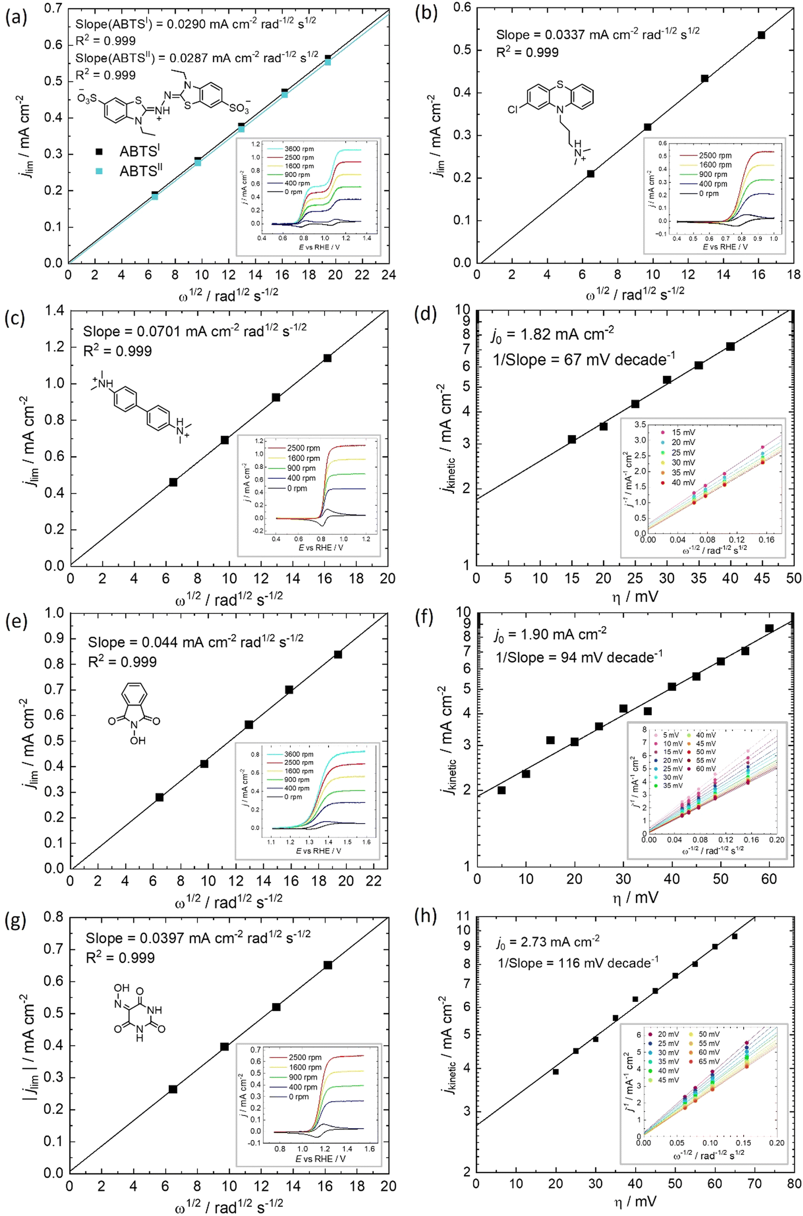 | ||
| Fig. 3 Determination of diffusivity coefficient and electrokinetic parameters of 2,2′-azinobis(3-ethylbenzothiazoline-6-sulfonate) (ABTS), chlorpromazine (CPZ), N,N,N′,N′-tetramethylbenzidine (TMB), N-hydroxyphthalimide (NHPI) and violuric acid (VIO). Levich plot of the limiting current (ilim) from iR-free and background-corrected RDE voltammetry profiles with 10 mV s−1 scan rate of (a) 1 mM ABTS measured at 0.907 V vs. RHE and the normalised limiting current (i0.907V – i1.247V) of the second-step (ABTSII) in 1 M HClO4, and 1 mM (b) CPZ, (c) TMB, (e) NHPI and (g) VIO in 1 M H2SO4 solutions. Tafel plot of the estimated linear region of the absolute kinetic current density vs. overpotential, from the Koutechy–Levich analysis of (e) TMB (f) NHPI and (h) VIO in 1 M H2SO4. | ||
| Supporting electrolyte | E vs. RHE/V | No. of e− | D/10−6 cm2 s−1 | km/10−6 cm s−1 | ke/10−2 cm s−1 | kcomp./10−4 cm s−1 | |
|---|---|---|---|---|---|---|---|
| a Electrokinetics too fast to measure with RDE technique.22,23 | |||||||
| ABTSI | 1 M HClO4 | 0.78 | 1 | 3.3 | 8.86 | >10a | 8.9 |
| ABTSII | 1 M HClO4 | 1.26 | 1 | 3.3 | 8.77 | >10a | 8.8 |
| CPZ | 1 M H2SO4 | 0.80 | 1 | 4.5 | 10.8 | >10a | 10.8 |
| TMB | 1 M H2SO4 | 0.83 | 2 | 4.8 | 11.2 | 0.9 | 10.0 |
| NHPI | 1 M H2SO4 | 1.34 | 1 | 6.7 | 14.1 | 2.0 | 13.1 |
| VIO | 1 M H2SO4 | 1.16 | 1 | 5.7 | 12.7 | 2.8 | 12.2 |
Table 1 displays the kinetic rate constant and the mass transfer rate constant, which allow for the evaluation of the theoretical “Intrinsic power” of any redox couple X. A hypothetical mass transfer rate constant km is derived from the following relationship, using the experimental km,(Fe2+/Fe3+) of 1.4 × 10⁻³ cm s−1 for the flow of iron chloride in an RFB felt at a superficial velocity of 1 cm s−1.24 The notional mass-transfer coefficient km,X of any positive redox couple X was derived as shown in eqn (1), in which the diffusion coefficients of Fe2+/Fe3+ (mean value) and of X are represented by DFe2+/Fe3+ and DX, respectively.
 | (1) |
For a fixed overpotential (when j = j0 and α = 0.5), the iR-free current consists of two terms, as shown in eqn (2) below, where jX is the notional current density of any positive redox couple X, n is the stoichiometric number of electrons transferred, F is the Faraday constant, ke,X is the standard kinetic constant of X and c* is the bulk concentration of X at 100% state-of-charge.25
 | (2) |
In the case that the kinetics are too facile to be measured by the RDE method, we assume 1/ke,X = 0. The influences of both rate constants can therefore be consolidated into a composite rate constant (kcomp,X) as so
 | (3) |
The term kcomp is therefore a single rate constant that incorporates both ke and D. The other key metric of a FB electrolyte is the specific energy density (EV), which in the H2–X system is the product of the potential (E0 vs. RHE) and the specific capacity (C/A h L−1). Plotted against one another, we can find the theoretical Joules per second (or Power) imparted from the positive electrolyte. This intrinsic power (Pintrinsic) is defined in eqn (4).
| Pintirinsic,X (×3.6 W cm−2) = kcomp,X (cm s−1)·EV (W h L−1) | (4) |
This is a useful comparator as we can extrapolate the relative merits and shortcomings of new FB electrolyte candidates from experimental data collected at very low concentrations. To do this, we have normalised the concentrations to 1 mol L−1, which is equivalent to 26.8 A h L−1 per e−. The end results are plotted in Fig. 4. ABTS, CPZ and TMB are highlighted in blue and the N-oxyl couples NHPI and VIO are shown in green.
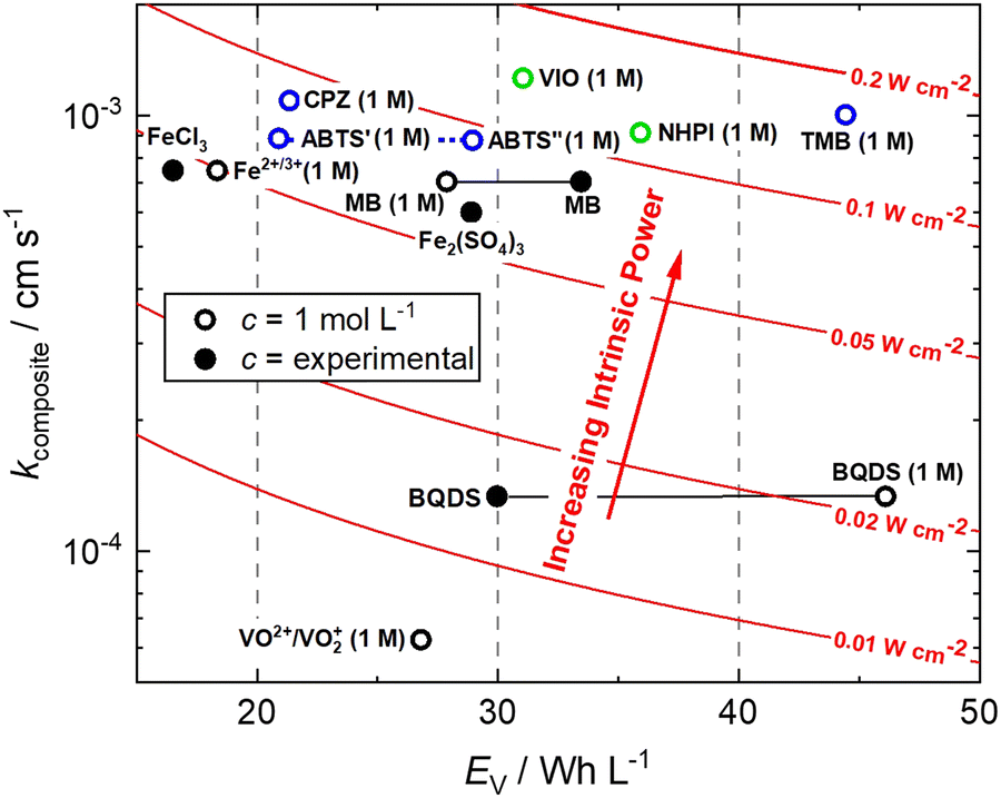 | ||
| Fig. 4 Intrinsic power of organic redox couples in a hypothetical H2–X RFC.15,16,24,26–28 ABTS: 2,2′-azinobis(3-ethylbenzothiazoline-6-sulfonate); BQDS: 2-dihydrobenzoquinone-3,5-disulfonic acid; CPZ: chlorpromazine; MB: methylene blue; NHPI: N-hydroxyphthalimide; TMB: N,N,N′,N′-tetramethylbenzidine; VIO: violuric acid. | ||
We have previously studied 1,2-dihydrobenzoquinone-3,5-disulfonic acid (BQDS) and methylene blue (MB) in the H2–X RFC, which achieved electrolyte concentrations of 0.65 M and 1.2 M respectively.15,16 Tucker et al. investigated FeCl3 and Fe2(SO4)3 salts in a H2–Fe RFC, tested at 0.9 M and 0.7 M respectively.29 These two RFB chemistries are also presented in Fig. 4, at their theoretical energy densities. From this information we can see that the rate constants of organic molecules are either comparable to or exceeding that of typically used metallic FB electrolyte ions of Fe and V. At concentrations of 1 mol L−1, the positive electrolyte capacities are all in excess of 20 W h L−1, with TMB achieving a theoretical capacity of 44.5 W h L−1. TMB also has the highest Pintrinsic value, followed closely by VIO, which although having a lower theoretical capacity makes up for this deficit by having a higher composite rate constant.
2.2. Evaluation of H2–organic cycling in a full cell
All of the redox couples were tested in a flow cell at a concentration of 5 mM in an appropriate supporting electrolyte, using a constant charge–discharge current density of 5 mA cm−2, with a 300 s open-circuit intermission between applied charge and discharge currents. The organic couples were the capacity limiting component of the cells. Galvanostatic cycling indicates the fade of the capacity-limiting electrolyte, yet it is important to note that the state-of-charge (SoC) achieved via this method can be subject to variations in the cell resistance and may not be an accurate quantification of capacity fade. To monitor the fade of relatively stable electrolytes, potentiostatic holds to complete conversion may be required. The UV-vis absorption spectrum (200–1000 nm) of the electrolyte was monitored throughout the initial cycle using a separate pumped electrolyte circuit (see ESI,† Fig. S2). From this information the initial structures in Fig. 5 of the organic species participating in the redox reactions were inferred. | ||
| Fig. 5 Determined redox reactions and potentials for (a) 2,2′-azinobis(3-ethylbenzothiazoline-6-sulfonate) (ABTS) in 1 M HClO4, and (b) chlorpromazine (CPZ), (c) N,N,N′,N′-tetramethylbenzidine (TMB),(d) N-hydroxyphthalimide (NHPI) and (e) violuric acid (VIO), in 1 M H2SO4. | ||
In neutral solution, ABTS dissolves as ABTS2−. The oxidation of ABTS2− (colourless) to the radical ABTS˙− is a useful kinetic probe due to the fast electron transfer in aqueous solutions.30 Scott et al. determined the pKa of ABTS2− to form HABTS− to be 2.08, and the spectroscopic analysis (Fig. 6b) of 5 mM ABTS in 1 M HClO4 at the 0% state-of-charge (SoC 0) was consistent with HABTS−.30 ABTS˙− is a metastable radical, aqueous samples of which are often prepared the day before use, as they can be stored overnight.31 It is possible that the comproportionation reaction in eqn (R1), between unprotonated ABTS2− and doubly oxidised state ABTS0, complicates further oxidation.4
| ABTS0 + ABTS2− → 2 ABTS˙− | (R1) |
 | ||
| Fig. 6 RFC test of 5 mM organic in 100 mL electrolyte cycled galvanostatically at 5 mA cm−2 and in-operando recorded UV-vis spectra at key points during the initial cycle of (a) and (b) ABTS, (c) and (d) CPZ and (e) and (f) TMB. | ||
In solutions of 1 M H2SO4, 1 mM ABTS requires a high scan rate (or a sub-millimolar concentration) to see a cathodic peak for the reduction of ABTS0, whereas in HClO4 both redox processes are reversible.4,30 The cell potential vs. capacity profile of 5 mM ABTS/1 M HClO4 in Fig. 6a indicates a possible self-discharge of the doubly oxidised state, as the first half of the charge process reaches a mass-transport overpotential before the ½Ctheo point of 0.134 A h L−1. During cycling, spectra appeared that were consistent with radical formation. However, the radical spectrum fluctuated at low levels with maximum intensities shortly after the charge starts and near ½Ctheo and did not linearly accumulate in the manner expected as though it were the product of bulk oxidation (see ESI,† Fig. S3).
When using 6 M H2SO4 as the supporting electrolyte, the H2–ABTS cell did not overshoot the theoretical maximum amount of charge transferred for 2 e− oxidation per molecule. In the initial (SoC 0) spectrum, the characteristic HABTS− peak was red-shifted to 294 nm with a shoulder at 285 nm. The capacity attained at 5 mA cm−2 was lower than in 1 M HClO4, but the whole cycle was completed in a similar timeframe (56 min vs. 55 min) with a 92.7% coulombic efficiency, compared to 45.8% for 5 mM ABTS in 1 M HClO4. The spectrum recorded at the maximum state-of-charge achieved (SoC 1), was characteristic of ABTS0, which notably was not apparent when 1 M HClO4 was used.32 It is important to note that the intensity of this peak (λmax = 516 nm) decayed by approximately ⅓rd in the 5-minute open-circuit time period before the discharge process began. As was also mentioned in the previous section, after standing, the 5 mM ABTS/6 M H2SO4 sample accumulated dark blue precipitate (ESI,† Fig. S4).
The oxidation and reduction of CPZ in 1 M H2SO4 is shown in Fig. 2 by a reversible cyclic voltammogram, which has a slight hysteresis possibly due to a layer of by-products that formed on the glassy carbon electrode surface following the oxidation of CPZ. The literature pKa of CPZ is 9.2–9.3, and so under the acidic conditions of the H2–X RFC the amine side-chain was considered to be protonated.33,34 The redox reaction of CPZ to form CPZ˙+ at ∼0.8 V vs. SHE is well-documented.35 It has also been shown to have a proton independent potential between pH 1.8–7.4, but that the temporal stability of the radical improves at lower pH.35 A second oxidation with an onset ∼1 V vs. RHE in 1 M H2SO4 showed no cathodic current. CPZ was therefore cycled in the cell with a potentiometric cut-off of only 0.95 V, to prevent the second electrochemical oxidation from occurring. The cell potential versus capacity profile is shown in Fig. 6c. Upon charging, the in-operando UV-vis spectra revealed the presence of a new species with a peak at λmax = 530 nm (Fig. 6d), which was characteristic of the vibrant red CPZ˙+ radical.36–38 For the full set of spectra obtained during the charging step see ESI,† Fig. S5. Despite the low cut-off cell voltage, the CPZ charging process smoothly surpassed the theoretical 1 e− per molecule capacity of 0.134 A h L−1 (Ctheo). The absorption peak at λmax = 530 nm (assigned to CPZ˙+) decreased slowly after Ctheo, and then decreased rapidly during the brief discharge process. The cell potential was high as the discharge commenced, indicating facile reversibility, however within a very short time the cell appeared to reach a reactant mass transport overpotential as a result of a low starting concentration of CPZ˙+. One explanation for the poor cyclability observed is the disproportionation of the radical in acidic solution as described in eqn (R2), which has also been put forward by Zhang et al.35
| 2 CPZ˙+ → CPZ + CPZ2+ | (R2) |
Emergent peaks at 240, 300 and 340 nm develop throughout the charging process, and are seen in the light blue spectrum in Fig. 6d, recorded immediately after the galvanostatic charge process. These three peaks are consistent with literature analyses of chlorpromazine sulfoxide (CPZO) absorption, and their intensity was unaffected even after the discharge process, shown by the green spectrum.39 CPZ2+ is thought to be reactive with water and quickly hydrolyses to form the sulfoxide, as shown in eqn (R3).35,40,41
| CPZ2+ + H2O → CPZO + 2 H+ | (R3) |
Therefore, it was shown that CPZ forms a significant amount of an electrochemically irreversible by-product before either a mass transport limit or the 0.95 V potentiometric limit was reached. This appeared to be due in part to a disproportionation reaction of CPZ˙+, and only residual CPZ˙+ allowed for a short-lived discharge current.
As shown in Fig. 6e, a H2–TMB cell could be cycled repeatedly and with a 99.8% discharge capacity retention over the course of 10 complete cycles (fade rate ∼0.2% day−1). The initial spectra of uncharged 5 mM TMB in 1 M H2SO4 electrolyte (Fig. 6f) showed a single absorption peak at λmax = 249 nm, which was consistent with the literature reports of 250 nm for the di-protonated TMBH22+ species.42–44 The behaviour and decay pathways of the oxidised states of TMB are dependent upon the degree of protonation.42 The disproportionation of the singly oxidised radical (TMB˙+) in acidic solution, as written in eqn (R4), with an equilibrium considerably to the right, has been documented in prior studies.43 The thermodynamic instability of TMB˙+ is also supported by the peak separation of 29 mV in the CV of TMB in 1 M H2SO4 in this work (Fig. 2).
| 2 TMB˙+ + 2 H+ → TMBH22+ + TMB2+ | (R4) |
When a 5 mA cm−2 charging current was applied in the H2–TMB cell, the TMBH22+ peak linearly decreased and was replaced by the characteristic spectrum of the TMB2+ dication, with a λmax = 465 nm, showing three isosbestic points at approximately 216.5, 222 and 284 nm. No perceivable absorption that could be attributed to the TMB˙+ radical was observed.42 A self-discharge reaction was evident from the voltage profiles and the spectral transformation over time, yet this could be largely mitigated by increasing the acid strength to 6 M H2SO4, in which case the cell no longer over-charged and the TMB2+ absorption peak retained 99.5% of its ‘SoC 1’ intensity over 72 h, measured at 425 nm (ESI,† Fig. S6).
The initial (SoC 0) spectrum of 5 mM NHPI in Fig. 7b was consistent with previous literature characterisations.14,45 During charging, the electrolyte turned from colourless to yellow, which is expected when the phthalimide N-oxyl (PINO) radical is formed. It can be assumed that the majority of PINO generated in the electrochemical cell also self-discharged to NHPI, which accounts for the 460% overcharge seen in Fig. 7a. No discharge current of the NHPI/PINO electrolyte was sustained at a current density of 5 mA cm−2, and the ‘Post-Charge’ spectrum in Fig. 7b characterises a degradation product.
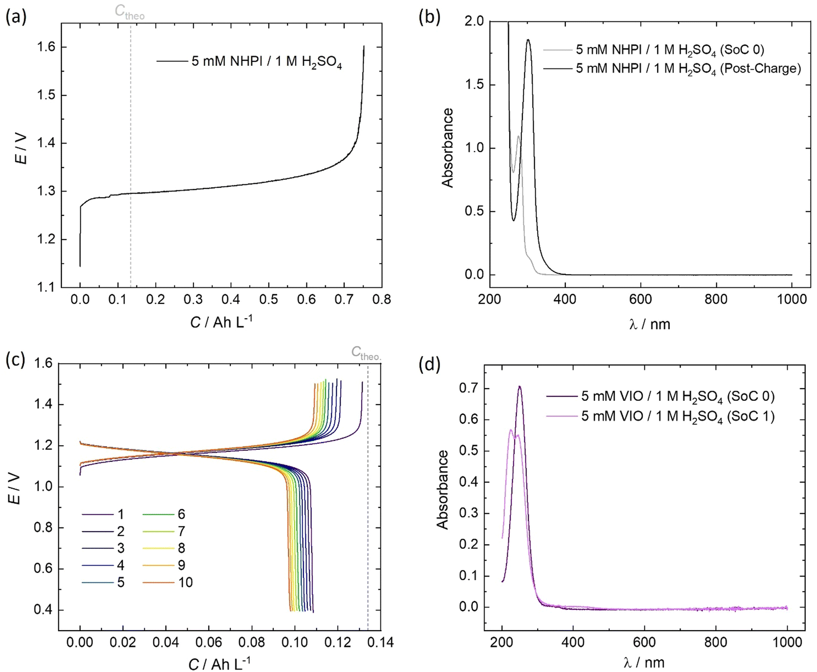 | ||
| Fig. 7 RFC test of 5 mM organic in 100 mL electrolyte cycled galvanostatically at 5 mA cm−2 and in-operando recorded UV-vis spectra at key points during the initial cycle of (a) and (b) NHPI and (c) and (d) VIO. | ||
In MeCN, VIO has a λmax = 250 nm, which was also seen in Fig. 7d for the spectrum of 5 mM VIO in 1 M H2O4.45 The charged state (‘SoC 1’) exhibited a red-shifted spectrum with an isosbestic point at 236.5 nm shared by the discharged and charged electrolyte. A lower coulombic efficiency can be reasonably expected on the first cycle, to account for the residual capacity in the depth-of-discharge attained at a fixed current density. However, as shown by the cell potential vs. specific capacity profiles in Fig. 7a, every charge of VIO was longer than the discharge, indicating some temporal instability. The small decrease of 9.7% in the discharge capacity over the course of 10 cycles (10.3 h) also indicates electrochemically irreversible degradation (∼23% day−1).
The final property to consider is the energy density that organic electrolytes can achieve. The solubility of the starting compound/organic salt in a solvent of acidic supporting electrolyte can give an idea of the suitability of each in a purely aqueous environment. Table 2 lists the maximum solubility attained in a solvent of the supporting electrolyte used in the tests in this work. Other than the molecular structure, the solubility can also be optimised by varying the ionic strength, temperature and counterion in some cases.
3. Conclusions
In recent years, a sizable collection of organic-based positive FB electrolytes have been studied.13 However, few have the requisite characteristics in terms of a high potential, stability and other important parameters. Many of the candidates applicable to the H2–X system are quinones or other bicarbonyl structures, yet here we have exclusively looked at alternative redox-active structural motifs to carbonyl-based couples.46As well as exploring new classes of organic molecules, it is also crucial to consider the suitability of the supporting electrolyte. As we have seen here and in our previous work, the impact of modifying the composition or ionic strength can have a drastic effect on the FB electrolyte characteristics, and should not be overlooked.15 For example, it was found that TMB2+ appears to temporally decay to TMBH22+ in 1 M H2SO4, whereas in 6 M H2SO4 the absorbance (and therefore inferred concentration) of TMB2+ showed a decay of only 0.168% per day. As was also previously mentioned, there is a pH-dependence to the stability of CPZ˙+ and ABTS˙−, and due to the extremely facile electrokinetics of these FB electrolyte chemistries the opportunity to improve their stability should be considered. The cell cycling performances and UV-vis spectra of H2–ABTS cells were also thoroughly inconsistent between electrolytes with supporting solutions of 6 M H2SO4 and 1 M H2SO4. Therefore, the effects of acid composition and pH on the stability and reversibility of promising organic electrolytes such as these provide scope for future investigation.
To summarise, we have demonstrated that several high potential FB electrolytes comprising of commercially prominent organic molecules can be used for energy storage. Three of the organic candidates investigated (ABTS, NHPI and VIO) undergo highly reversible redox reactions at potentials of >1.0 V vs. RHE. This corresponds to a higher cell potential than the H2–V RFC system. The H2–VIO cell in particular was shown to cycle with promising reversibility, and with a cell potential only 0.1 V lower than the V–V symmetrical FB system. Although it has only a 1 e− mol−1 capacity, the VIO redox couple has shown promising aqueous stability, and the high redox potential proves that N-oxyl compounds can be suitable candidates for acidic FB electrolyte systems. In practise, organic-based FB electrolytes may help separate the overall CAPEX (per kWh) of EES from the value of non-abundant metals.
4. Experimental section
Electrochemical characterisation data was obtained using a 5 mm polished glassy carbon disk as the working electrode in a rotor (Pine instruments), a graphite rod counter electrode, and a saturated calomel electrode (SCE) reference or an in-house made reversible hydrogen electrode (RHE) in a 3-compartment cell. All results were recorded on a Autolab PGSTAT302N and corrected to the RHE scale. Rotating disk electrode (RDE) measurements were recorded at a scan rate of 10 mV s−1. All RDE data was iR and background corrected. Cyclic voltammograms were measured at a scan rate of 50 mV s−1 and background corrected. Diammonium 2,2′-azinobis(3-ethylbenzothiazoline-6-sulfonate), N-hydroxyphthalimide and chlorpromazine hydrochloride (Sigma Aldrich), N,N,N′,N′-tetramethylbenzidine (Thermo Scientific Chemicals) and violuric acid (Alfa Aesar) were used as received. Aqueous electrolyte solutions of were prepared using 95% H2SO4 (Normapur, VWR) or 60% HClO4 (VWR) diluted with 18.2 MΩ ultrapure water from a Sartorius system. All 2- and 3-electrode measurements were performed at room temperature.Electrochemical flow-cell experiments were recorded using a Scribner 857 RFB test station. Galvanostatic charge–discharge cycles were performed using a 5 cm2 cell at ±5 mA cm−2 to the maximum possible depth-of-discharge within custom cell voltage limits, using 100 mL electrolyte samples. 190 μm, 0.4 mgPt cm−2 electrode (ELE0201, Johnson Matthey Fuel Cells) was used for the H2-side electrode, and 4.6 mm carbon felt (Sigracell) for the liquid side, which was oxygen plasma treated (Diener) immediately before use. For ABTS cell tests, Nafion 212 was pre-treated by soaking the membrane in 5% H2O2 for 1 h at 80 °C. This was repeated with ultrapure pure water, then 1 M H2SO4. For all other cell tests the phosphoric acid-doped PBI (Celtec, BASF) membrane was used as received. The gaskets (Tygaflor) ensured membrane electrode assembly was compressed by ∼20% with 4.0 N m applied torque to the 5 cm2 flow cell (Scribner Associates). Hydrogen gas was produced from an electrolyser (60H-FUEL Hydrogen Generator, Parker) and flowed at a 100 mL min−1 constant rate using a H2 mass-flow controller (El-Flow Select, Bronkhorst) and the relative humidity was set at 98–100% by flowing through a humidification column (Perma Pure MH-110-12S-2). The positive electrolyte was flowed at a constant rate of 50 mL min−1 and without any protection from air. In-operando absorption spectra were recorded on a UV-vis photospectrometer (Evolution 220, Thermo Scientific) with a flow-through cuvette of 0.01 cm path (48/Q/0.1, Starna) or a 0.2 cm cuvette (48-4/Q/2, Starna) for the NHPI cell test, with the wavelength range of 1000–200 nm and a frequency of 1 spectrum min−1.
The maximum concentrations were determined from the magnitude of the absorbance, within the calibration range (Fig. S7, ESI†) of the absorbance. The peak absorbance was measured in a 1 cm path length quartz cuvette. Each compound/organic salt was added to a supporting electrolyte solution until saturation, at room temperature. The liquid phase was isolated by passing the saturated mixture through a syringe-filter (PTFE 0.2 μm, fisherbrand) and was then diluted in 1 M H2SO4 to obtain a peak absorption within the calibration range, where the Beer–Lambert law was applicable.
Author contributions
CC and AK conceived the MS; CC performed all the experiments under the supervision of AK, NB and PK. CC wrote the MS with additions by AK; All authors contributed to editing the MS.Data availability
Data for this article, used in the production of the figures are available at https://doi.org/10.5281/zenodo.13712672.Conflicts of interest
One of us (Kucernak) is inventor on a patent application for organic hydrogen reversible fuel cells (WO2020109807A1). CC, AK and NB are coinventors on a patent application has been filed on aspects of this work.Acknowledgements
One of us (CC) acknowledges the support of UKRI and Shell Global Solutions International B.V. for an Industrial CASE studentship (210104). We acknowledge the kind donation of Celtec membranes from BASF.References
- R. M. Darling, K. G. Gallagher, J. A. Kowalski, S. Ha and F. R. Brushett, Energy Environ. Sci., 2014, 7, 3459–3477 RSC.
- S. Gentil, D. Reynard and H. H. Girault, Curr. Opin. Electrochem., 2020, 21, 7–13 CrossRef CAS.
- V. Singh, S. Kim, J. Kang and H. R. Byon, Nano Res., 2019, 12, 1988–2001 CrossRef CAS.
- R. Bourbonnais, D. Leech and M. G. Paice, Biochim. Biophys. Acta, Gen. Subj., 1998, 1379, 381–390 CrossRef CAS PubMed.
- B. S. Wolfenden and R. L. Willson, J. Chem. Soc., Perkin Trans. 2, 1982, 805–812 RSC.
- F. López-Muñoz, C. Alamo, G. Rubio and E. Cuenca, Prog. Neuro-Psychopharmacol. Biol. Psychiatry, 2004, 28, 205–208 CrossRef PubMed.
- X. Liu, T.-C. Cai, D. Guo, B.-B. Wang, S. Ying, H. Wang, S. Tang, Q. Shen and Q.-W. Gui, Tetrahedron Lett., 2021, 70, 153021 CrossRef CAS.
- T. Gessner and U. Mayer, Ullmann's Encyclopedia of Industrial Chemistry, Wiley-VCH Verlag GmbH & Co. KGaA, 2000 Search PubMed.
- V. Guichard, A. Bourkba, O. Poizat and G. Buntinx, J. Phys. Chem., 1989, 93, 4429–4435 CrossRef CAS.
- Y. Hirata, M. Takimoto and N. Mataga, Chem. Phys. Lett., 1983, 97, 569–572 CrossRef CAS.
- W. Zhou, W. Liu, M. Qin, Z. Chen, J. Xu, J. Cao and J. Li, RSC Adv., 2020, 10, 21839–21844 RSC.
- T. Janoschka, N. Martin, M. D. Hager and U. S. Schubert, Angew. Chem., Int. Ed., 2016, 55, 14427–14430 CrossRef CAS PubMed.
- C. G. Cannon, P. A. A. Klusener, N. P. Brandon and A. Kucernak, ChemSusChem, 2023, e202300303 CrossRef CAS PubMed.
- Y. Tian, K. H. Wu, L. Cao, W. H. Saputera, R. Amal and D. W. Wang, Chem. Commun., 2019, 55, 2154–2157 RSC.
- C. G. Cannon, P. A. A. Klusener, L. F. Petit, T. Wong, A. Wang, Q. Song, N. P. Brandon and A. R. J. Kucernak, ACS Appl. Energy Mater., 2024, 7, 2080–2087 CrossRef CAS PubMed.
- J. Rubio-Garcia, A. Kucernak, A. Parra-Puerto, R. Liu and B. Chakrabarti, J. Mater. Chem. A, 2020, 8, 3933–3941 RSC.
- Y. Xu, Y. Wen, J. Cheng, Y. Yanga, Z. Xie and G. Cao, WNWEC 2009 - 2009 World Non-Grid-Connected Wind Power and Energy Conference, 2009, 475-478.
- L. Hoober-Burkhardt, S. Krishnamoorthy, B. Yang, A. Murali, A. Nirmalchandar, G. K. S. Prakash and S. R. Narayanan, J. Electrochem. Soc., 2017, 164, A600–A607 CrossRef CAS.
- A. W. Lantz, S. A. Shavalier, W. Schroeder and P. G. Rasmussen, ACS Appl. Energy Mater., 2019, 2, 7893–7902 CrossRef CAS.
- L. H. Brickwedde, J. Res. Natl. Bur. Stand., 1949, 42, 309 CrossRef CAS.
- H. E. Darling, J. Chem. Eng. Data, 1964, 9, 421–426 CrossRef CAS.
- A. J. Bard and L. R. Faulkner, Electrochemical methods: fundamentals and applications, John Wiley & Sons, Inc., Hoboken, NJ, 2nd edn, 2001 Search PubMed.
- H. Wang, S. Y. Sayed, E. J. Luber, B. C. Olsen, S. M. Shirurkar, S. Venkatakrishnan, U. M. Tefashe, A. K. Farquhar, E. S. Smotkin, R. L. McCreery and J. M. Buriak, ACS Nano, 2020, 14, 2575–2584 CrossRef CAS PubMed.
- X. You, Q. Ye and P. Cheng, J. Electrochem. Soc., 2017, 164, E3386–E3394 CrossRef CAS.
- C. M. A. Brett and A. M. O. Brett, Kinetics and Transport in Electrode Reactions, Oxford University Press, 1993 Search PubMed.
- D. Stephenson, S. Kim, F. Chen, E. Thomsen, V. Viswanathan, W. Wang and V. Sprenkle, J. Electrochem. Soc., 2012, 159, A1993–A2000 CrossRef CAS.
- T. Yamamura, N. Watanabe, T. Yano and Y. Shiokawa, J. Electrochem. Soc., 2005, 152, A830 CrossRef CAS.
- D. C. Harris, Quantitative Chemical Analysis, W.H. Freeman and Company, New York, 6th edn, 2003 Search PubMed.
- M. C. Tucker, V. Srinivasan, P. N. Ross and A. Z. Weber, J. Appl. Electrochem., 2013, 43, 637–644 CrossRef CAS.
- S. L. Scott, W. J. Chen, A. Bakac and J. H. Espenson, J. Phys. Chem., 1993, 97, 6710–6714 CrossRef CAS.
- I. R. Ilyasov, V. L. Beloborodov, I. A. Selivanova and R. P. Terekhov, Int. J. Mol. Sci., 2020, 21, 1131 CrossRef CAS PubMed.
- L. Venkatasubramanian and P. Maruthamuthu, Int. J. Chem. Kinet., 1989, 21, 399–421 CrossRef CAS.
- T. Kitagawa, A. Mastumoto, I. Terashima and Y. Uesono, J. Med. Chem., 2021, 64, 3885–3896 CrossRef CAS PubMed.
- F. Martinez-Rojas, C. Espinosa-Bustos, G. Ramirez and F. Armijo, Electrochim. Acta, 2023, 443, 141873 CrossRef CAS.
- M. Zhang, W.-Q. Bao, Y. Wang, N. Deng and J.-B. He, J. Electroanal. Chem., 2014, 724, 1–7 CrossRef CAS.
- D. Daniel and I. G. R. Gutz, J. Pharm. Biomed. Anal., 2005, 37, 281–286 CrossRef CAS PubMed.
- E. Bosch and J. K. Kochi, J. Chem. Soc., Perkin Trans. 1, 1995, 1057–1064 RSC.
- K. Minakata, O. Suzuki, Y. Ishikawa, H. Seno and N. Harada, Forensic Sci. Int., 1992, 52, 199–210 CrossRef CAS.
- A. A. Fasanmade and A. F. Fell, Analyst, 1985, 110, 1117–1124 RSC.
- G. R. Buettner, A. G. Motten, R. D. Hall and C. F. Chignell, Photochem. Photobiol., 1986, 44, 5–10 CrossRef CAS PubMed.
- A. G. Motten, G. R. Buettner and C. F. Chignell, Photochem. Photobiol., 1985, 42, 9–15 CrossRef CAS PubMed.
- R. Arce and L. Kevan, J. Chem. Soc., Faraday Trans. 1, 1985, 81, 1669–1676 RSC.
- S. M. Beck and L. E. Brus, J. Am. Chem. Soc., 1983, 105, 1106–1111 CrossRef CAS.
- S. Hashimoto and J. K. Thomas, J. Phys. Chem., 1984, 88, 4044–4049 CrossRef CAS.
- M. Homocianu, G. Biliuta, A. Airinei and S. Coseri, Optoelectron. Adv. Mater., Rapid Commun., 2011, 5, 567–571 CAS.
- P. Fischer, P. Mazúr and J. Krakowiak, Molecules, 2022, 27, 560 CrossRef CAS PubMed.
Footnote |
| † Electronic supplementary information (ESI) available. See DOI: https://doi.org/10.1039/d4ya00366g |
| This journal is © The Royal Society of Chemistry 2024 |