 Open Access Article
Surface engineering of a 2D CuFe-LDH/MoS2 photocatalyst for improved hydrogen generation†
Chandra Shobha
Vennapoosa
ab,
Sandip Prabhakar
Shelake
bc,
Bhavya
Jaksani
ab,
Aparna
Jamma
ab,
B.
Moses Abraham
 d,
Annadanam V.
Sesha Sainath
bc,
Mohsen
Ahmadipour
e and
Ujjwal
Pal
 *ab
*ab
aDepartment of Energy & Environmental Engineering, CSIR-Indian Institute of Chemical Technology, Tarnaka, Hyderabad, Telangana 500007, India. E-mail: upal03@gmail.com; ujjwalpal@iict.res.in
bAcademy of Scientific & Innovative Research (AcSIR), Ghaziabad, Uttar Pradesh 201002, India
cPolymers and Functional Materials and Fluoro-Agrochemicals Department, CSIR-Indian Institute of Chemical Technology, Uppal Road, Hyderabad 500007, India
dDepartment of Chemical Engineering, Indian Institute of Technology Kanpur, Kanpur 208016, India
eInstitute of Power Engineering, Universiti Tenaga Nasional, 43650 Serdang, Selangor, Malaysia
First published on 16th February 2024
Abstract
Creating effective heterostructure photocatalysts with S-scheme-based charge-transfer dynamics enables efficient electron transfers, thereby enhancing visible-light-induced photocatalytic hydrogen production. In this report, we investigate a series of CuFe-LDH/MoS2 composites synthesized by employing MoS2 with CuFe-LDH through a self-assembled chemical method and an in situ hydrothermal process. The morphological features illustrate a consistent stacked nanosheet-like structure. The enhanced electronic and optical properties of the as-prepared CuFe-LDH/MoS2 and their improved photocatalytic hydrogen evolution execution is credited to the S-scheme heterojunction preventing the recombination of photogenerated charge transporters and improving the fast charge transference and utilization. The CuFe-LDH/MoS2 photocatalyst exhibits a superior photocatalytic H2 creation rate of 3.4 mmol g−1 h−1 and an AQY of 1.3% compared to CuFe-LDH (1.3 mmol g−1 h−1; AQY:0.5%). DFT studies reveal that the synergistic effects of the CuFe-LDH/MoS2 interface effectively enhance both the thermodynamics and kinetics of the rate-determining step for the hydrogen evolution reaction, which aligns with the experimental results. This design approach paves the way for creating highly efficient photocatalysts for future research in this promising domain.
Introduction
Solar energy stands as an endless, environmentally friendly, and sustainable energy source on our planet. Generating hydrogen from water using solar energy is often considered one of the cleanest forms of energy production.1–3 Under solar irradiation, a photocatalyst instigates the activation of water molecules, leading to the generation of hydrogen and oxygen, thus efficiently transmuting solar energy into hydrogen.4–9 Nevertheless, the realm of photocatalysis presents numerous exigencies necessitating further investigation, including strategies for mitigating electron–hole pair recombination and addressing photocatalyst photo-corrosion.10–12 Consequently, the imperative remains to cultivate a resilient and highly efficient photocatalyst.LDH is categorized as a two-dimensional material (2D), characterized by positively charged layers where the positive charge is counterbalanced by different anions residing between the layers. Consequently, LDH as a whole remains electrically neutral and retains a contingent presence of H2O molecules.13–15 The structural chemical formula for LDH can be expressed as [M1−x2+Mx3+(OH)2][X+ Ax/n]n−mH2O, encompassing divalent metal cations such as Ni2+, Mg2+, Cu2+, and Zn2+ (with a valence of +2), and trivalent metal cations including Al3+, Fe3+, Cr3+, and Sc3+ (with a valence of +3).16,17 Owing to the advantageous characteristics of variable elemental composition, a substantial precise surface area, and robust stability exhibited by LDHs, their structural features can be readily tailored and controlled. Consequently, LDHs find extensive applications in the fields of photocatalysis and electrocatalysis.18–20 However, owing to the sluggish transference rate of photogenerated transporters produced by individual LDHs upon photo excitation; LDHs alone lack a pronounced impact on H2 evolution.21–23 Hence, various strategies have been devised to enhance the H2 evolution efficiency, such as the construction of heterojunctions or the reinforcement of coupling between two semiconductors. For instance, NiAl-LDH/CdS promotes H2 evolution by establishing S-schemes that consume superfluous e− and h+.24 The synthesis of CoAl-LDH/RGO nanocomposites through a solvothermal method effectively facilitates the transfer and separation of photogenerated charge carriers, thereby enhancing the composite properties.25,26
In the field of photocatalysis, molybdenum sulfides (Mo sulfides), notably MoS2, have become the most prospective platinum (Pt) substitutes.27,28 In contrast, MoS2 is an intrinsically n-type semiconductor containing a sandwich-like stacked S–Mo–S fashion in a stack of planes that are closely filled in a hexagonal arrangement and have a van der Waals interaction between two adjacent planes. The indirect and direct band gaps are 1.2 eV, but MoS2 lies within 1.9 eV, which is mostly employed in photocatalysis.29 This material has garnered substantial attention within the photocatalysis community due to its wide availability, favorable electrical conductivity, and facile synthesis.30 Moreover, MoS2 exhibits exceptional photocatalytic performance attributed to its robust light absorption capabilities within the visible spectrum, chemical stability, and narrow band gap.31 MoS2 has found extensive utility in photocatalysis, with notable examples including the TiO2/MoS2,32 MoS2/g-C3N4,33 and CuO@ZnO34 systems, which leverage heterojunction construction to expedite the separation of photoinduced charge carriers and enhance H2 production. To bolster the efficiency of photocatalytic water splitting, various heterojunction types, such as type Z, type I, and type II, can be engineered. The S-scheme heterojunction encompasses considerations of band bending, electrostatic interactions between semiconductor materials, and the creation of intrinsic electric fields, thus enriching the model conditions relative to alternative heterojunction configurations.35–37 Within this context, the S-scheme heterojunction achieved by combining CuFe-LDH and MoS2 serves to not only suppress the recombination of photoinduced charge carriers but also enhance the production of H2 gas.
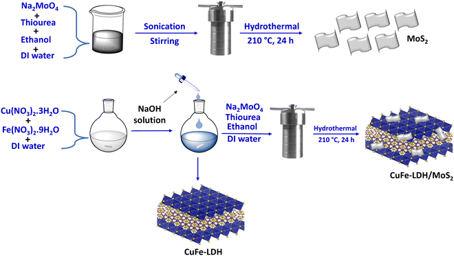
In the current study, we have constructed an S-scheme photocatalyst by combining 2H-MoS2 and CuFe-LDH, which act as the building blocks for constructing type-II CuFe-LDH/MoS2 electrostatic heterostructures through hydrothermal processes, as detailed in Scheme 1. Initially, LDH exhibits limited charge carrier conductivity. Nevertheless, the establishment of a heterojunction with MoS2 substantially elevates their conductivity by facilitating charge carrier transport. This enhancement proves advantageous for the promotion of more effective photocatalytic redox reactions. The persistent coverage of CuFe-LDH nanosheets with MoS2 nanosheets reveals a highly efficient pathway for the transfer of holes from CuFe-LDH to the scavenger in the oxidation reaction, and the transfer of electrons from MoS2 for the reduction reaction, as observed in the S-scheme charge separation mechanism. Furthermore, we investigated the photocatalytic efficacy of various composite catalysts, and it was established that the CuFe-LDH/MoS2 photocatalyst exhibited superior photocatalytic performance. The formation of an S-scheme heterojunction reduced the recombination of photogenerated carriers, resulting in a notable enhancement of the transfer of photogenerated charges at the catalyst interface. Additionally, an in-depth investigation of the photochemical properties and intrinsic mechanisms of CuFe-LDH/MoS2 was carried out. This research has effectively enhanced the photocatalytic hydrogen production capabilities of the catalyst through straightforward methods, thereby increasing its potential for significant advancement in the realm of photocatalytic hydrogen production.
Results and discussion
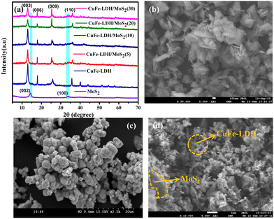
The crystallographic structures of the powders were initially synthesized via X-ray diffraction (XRD) analysis, as depicted in Fig. 1(a). The intrinsic diffraction features corresponding to the hydrotalcite-like structure were discernible in the XRD pattern of CuFe-LDH.38 Specifically, the peaks observed at 2θ values of 13.1°, 23.7°, 34.2°, and 59.8° corresponded to the (003), (006), (009), and (110) planes of CuFe LDH, respectively (Fig. 1(a)). In the XRD patterns of MoS2 and CuFe-LDH/MoS2, three distinct diffraction peaks at 14.41°, and 32.71° were associated with the (002), and (100) crystallographic planes of MoS2, respectively.39 The XRD patterns of the CuFe-LDH/MoS2-(x), which were fabricated with different levels of MoS2 loading (x = 5, 10, 20, 30), are presented in Fig. 1(a). These profiles exhibited concurrent diffraction peaks attributable to both MoS2 and CuFe-LDH, affirming that the introduction of MoS2 did not perturb the chemical composition of CuFe-LDH throughout the synthesis of CuFe-LDH/MoS2. This observation is consistent with the relatively trace amount of MoS2 nanosheets in the composite, as shown in Fig. S1 (ESI†).39 It's noteworthy that the diffraction peaks attributed to CuFe-LDH maintained their clarity in the composite photocatalysts, affirming that the initial introduction of MoS2 did not interfere with the crystalline structure of MoS2.Fig. 1(b)–(d) presents typical field emission scanning electron microscopy (FESEM) images of CuFe-LDH, MoS2, and CuFe-LDH/MoS2(20). In Fig. 1(b), it is evident that the unmodified CuFe-LDHs exhibit a flaky nanosheet morphology, which is a characteristic feature of exfoliated LDH materials, as previously observed.40Fig. 1(c) illustrates the sheet-like morphology of MoS2. The morphology depicted in Fig. 1(d) for CuFe-LDH/MoS2(20) reveals the successful growth of hexagonal, flaky MoS2 nanosheets on the CuFe-LDH sheets, in accordance with prior research findings.39 These results indicate that CuFe-LDH effectively impedes the aggregation of MoS2 nanoplatelets within CuFe-LDH/MoS2(20), and conversely, electrostatic interactions between LDH and MoS2 preserve their original nanosheet morphologies in CuFe-LDH/MoS2(20) (Fig. 1(d)). In Fig. S3(a) and (b) (ESI†), the nitrogen (N2) adsorption and desorption curves for the examined samples are presented. Evidently, the CuFe-LDH/MoS2(20) composite exhibits a characteristic type IV isotherm, accompanied by a specific surface area of 125.4 m2 g−1 and a pore diameter of 11.19 nm, falling within the conventional mesoporous size range. Subsequently, upon comparative analysis of the respective images, it becomes apparent that CuFe-LDH/MoS2(20) outperforms CuFe-LDH and MoS2 in both specific surface area and pore diameter. This observation signifies the utilization of two-dimensional materials in augmenting the specific surface area of the composite catalyst and promoting the rate of H2 evolution during the reaction.
The microstructural characteristics, chemical composition, and crystallographic features of the prepared MoS2, CuFe-LDH, and CuFe-LDH/MoS2(20) materials were further elucidated through transmission electron microscopy (TEM) and high-resolution TEM (HR-TEM) analyses, as depicted in Fig. 2. In Fig. 2(a), CuFe-LDH appeared as an aggregation of hexagonal nanosheets, with an average diameter ranging from 20 to 30 nm. The HR-TEM image of CuFe-LDH shown as an inset in Fig. S2(c) (ESI†) revealed distinct lattice fringes, signifying a clearly defined crystal structure. The lattice spacing was measured at 0.25 nanometers, corresponding to the (012) plane of hexagonal CuFe-LDH nanosheets, as reported previously.40 The synthesized MoS2 nanosheets exhibited interconnectivity, and formation of a self-organized assembly of exfoliated nanosheets with only a few layers, as illustrated in Fig. S2(a) (ESI†). The HR-TEM image displayed interlayer lattice fringes with a lattice spacing measuring 0.22 nm, corresponding to the (103) crystallographic orientations of MoS2, as presented in Fig. S2(b) (ESI†).39 In contrast to the LDHs, significant alterations in the morphological characteristics of CuFe-LDH/MoS2(20) were observed, as depicted in Fig. 2(c) and (d). Notably, LDHs were effectively coated by MoS2. Fig. 2(c) and (d) present TEM images of the heterostructured CuFe-LDH/MoS2(20) nanocomposite, demonstrating uniform morphology across the heterostructure nanocomposites. Fig. 2(d) highlights the self-assembly of MoS2 and CuFe-LDH nanosheets, leading to the creation of a structure with precise alignment in the opposing growth orientation of CuFe-LDH and MoS2, resulting in heterointerfaces. Moreover, the HR-TEM image depicted in Fig. 2(c), which revealed interplanar lattice spacings of 0.22 nm and 0.25 nm, was associated with the (103) and (012) interplanar planes of a few-layered MoS2 and CuFe-LDH, respectively. The presence of heterogeneous nanojunctions within the CuFe-LDH/MoS2(20) nanocomposite was distinctly evident in the HR-TEM image. This image clearly depicted the development of lattice fringes in opposing directions and distinct barriers between MoS2 and CuFe-LDH layers. This observation suggests that few-layer MoS2, characterized by an interlayer spacing of 0.22 nm, establishes close contact with CuFe-LDH facilitating the formation of nanoscale interfaces, enabling efficiency for the separation and transfer of photoexcited exciton pairs, thereby enhancing catalytic performance. The elemental distribution of each metal constituent within the electrostatic heterostructure CuFe-LDH/MoS2(20) nanocomposite was quantitatively assessed through EDX spectroscopy measurements (Fig. 2(d)–(i)). All elements, including Mo, S, Cu, Fe, S, and O, exhibited high-intensity signals, indicating a uniform distribution of each element throughout the few-layered CuFe-LDH/MoS2(20) nanocomposite. During the growth process, the well-dispersed CuFe-LDH nanosheets offered active surfaces for the nucleation and expansion of MoS2, playing a pivotal role in shaping the hierarchical structural arrangement. The development of heterostructures featuring edge-bound, thinly-layered MoS2 and CuFe-LDH nanosheets resulted in enhanced chemical and physical characteristics, particularly in terms of photocatalytic performance. The existence of additional basal edge sites, which contain unsaturated sulfur ions, efficiently constrained H+ ions within the close interface between MoS2 and CuFe-LDH nanosheets, thereby enhancing exceptional redox reaction capabilities.41
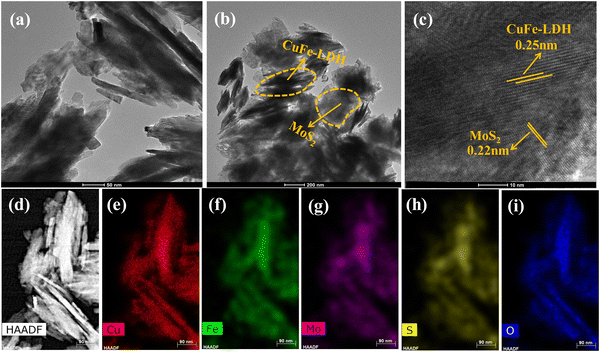 | ||
| Fig. 2 TEM images of (a) CuFe-LDH, (b) CuFe-LDH/MoS2(20), (c) HR-TEM image of CuFe-LDH/MoS2(20) and (d)–(i) HAADF-STEM and elemental analysis of CuFe-LDH/MoS2(20). | ||
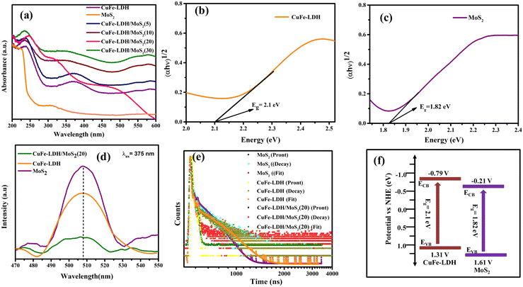
Assessing catalyst performance and its responsiveness to visible light is a crucial aspect of catalytic studies. To investigate their light absorption capabilities, we conducted UV-visible diffuse reflectance spectroscopy (UV-vis DRS) on CuFe-LDH, MoS2, and CuFe-LDH/MoS2(20). As illustrated in Fig. 3(a), CuFe-LDH exhibited three absorption bands within the visible light range. The absorption band in the 200–300 nm range can be attributed to ligand-to-metal charge transfer (from O 2p orbit to Cu 3dt2g), while the dual-band in the 300–500 nm range is associated with the octahedral structure (d–d transition of Cu2+), both characteristic of visible light absorption.41 Both MoS2 and CuFe-LDH/MoS2-(x) exhibited comprehensive light absorption throughout the visible light spectrum, a characteristic attributed to the utilization of black MoS2 in the preparation process and the substantial proportion of MoS2 content within the composite catalyst. The band gap energies of CuFe-LDH, MoS2, and CuFe-LDH/MoS2 were calculated from the corresponding Kubelka–Munk function and Tauc plot as follows (eqn (1)).41
| (αhν)1/n = A(hν − E) | (1) |
The intensity of the photoluminescence spectrum (PL) peaks serves as an indicator of the recombination rate of photogenerated electrons and holes within different catalysts. Notably, when subjected to excitation at a 375 nm wavelength, the samples exhibited maximum emission peaks at around 507 nm, as illustrated in Fig. 3(d). Furthermore, it was noted that the fluorescence intensity of the CuFe-LDH/MoS2(20) composite was less pronounced in comparison to the pristine CuFe-LDH and MoS2.42 This reduction can be attributed to the efficient separation and transfer of a significant number of electrons and holes within CuFe-LDH/MoS2(20). Consequently, fewer opportunities for recombination arise, resulting in weaker fluorescence in CuFe-LDH/MoS2(20). This phenomenon, in turn, facilitates photocatalytic reactions. The electron lifetimes of the photogenerated electrons were determined by analyzing time-resolved photoluminescence (TRPL) spectra, utilizing an excitation wavelength above 385 nm, which resulted in a pronounced emission peak at 578 nm. Additionally, photon count data were extracted from the TRPL spectra. For all photocatalysts examined, two distinct electron lifetimes were observed, with shorter and longer durations associated with surface emissions linked to defect generation and internal electron transfer, respectively. The average lifetimes for CuFe-LDH, MoS2, and CuFe-LDH/MoS2(20) were measured at 0.54 ns, 0.61 ns and 0.42 ns, as depicted in Fig. 3(e). These findings indicate that the diminished lifetime of the heterojunction photocatalyst is mainly attributed to non-radiative photo-decay, representing a pathway for electron transfer from the conduction band of MoS2 to the valence band of LDH, effectively inhibiting the recombination of electron–hole pairs.
The arrangement of the heterojunction interface can impede exciton pair recombination and accelerate surface chemical reactions. The evaluation of junction properties is facilitated through the examination of the alignment of energy bands and energy states at the interface. To investigate these aspects, we employed high-resolution X-ray photoelectron spectroscopy (XPS) to examine the energy states of constituent elements within the CuFe-LDH/MoS2 heterojunction interfaces. The XPS analysis revealed detectable signals corresponding to elements Mo, S, Cu, Fe, C, and O in a wide XPS spectrum, thus confirming the formation of heterostructure nanocomposites CuFe-LDH, MoS2, and CuFe-LDH/MoS2 (Fig. 4(a)). Furthermore, the transfer of electrons from the MoS2 to the CuFe-LDH within the CuFe-LDH/MoS2 system, facilitated through S-scheme charge transfer, was substantiated by XPS analysis of pristine MoS2 and CuFe-LDH. In the pristine CuFe-LDH, the Cu 2p3/2 and Cu 2p1/2 spectrum (Fig. 4(b)) exhibited peaks at 931.2 and 951.0 eV corresponding to the primary Cu2+ state, along with two prominent shake-up satellite peaks observed at 940.2 and 960.5 eV, respectively.43,44 Additionally, the Cu 2p spectrum of CuFe-LDH/MoS2 was subjected to peak-fitting analysis to elucidate the nature of the Cu phase and its interaction with MoS2 (Fig. 4(b)). Following the formation of a heterostructure between CuFe-LDH and MoS2, the Cu 2p peaks associated with CuFe-LDH/MoS2 exhibited a noticeable blue shift towards higher binding energy (BE), with an energy shift of approximately 0.2 eV. The deconstructed Cu 2p XPS spectrum of CuFe-LDH/MoS2 provided further validation of the presence of Cu2+ in the system. In Fig. 4(b), two pairs of spin–orbit peaks, observed at BEs of 931.4 and 951.2 eV, corresponded to Cu 2p3/2 and Cu 2p1/2, respectively, and were accompanied by two satellite peaks at 940.2 and 960.7 eV. In the unmodified CuFe-LDH (Fig. 4(c)), distinctive peaks at 712.9 and 725.9 eV indicated the existence of Fe3+ species. In contrast, CuFe-LDH/MoS2 displayed a 0.2 eV shift to higher energies in the Fe 2p peaks, with two primary peaks observed at 713.3 and 726.1 eV, corresponding to Fe 2p3/2 and Fe 2p1/2, respectively.45 The broader Fe 2p peaks observed in CuFe-LDH/MoS2, as compared to pure CuFe-LDH, suggest a change in the chemical environment of iron, likely induced by interactions with MoS2. This alteration is evident in the shifted peaks following the introduction of Fe into the CuFe-LDH matrix (formation of CuFe-LDH/MoS2). The introduction of Fe significantly influences the chemical environment of CuFe-LDH/MoS2, it is crucial to determine the valence state of the Fe species, as it could play a vital role in catalytic activity.46 This observation suggests that Cu and Fe are present in the Cu2+ and Fe3+ oxidation states within the CuFe-LDH/MoS2 nanocomposites, respectively. Furthermore, the appearance of a satellite peak and a higher BE shift in the Cu 2p primary line signifies the existence of octahedral geometry, specifically the [CuO6] entities in CuFe-LDH/MoS2. In the comparison of the decomposed O 1s spectrum of pure CuFe-LDH with that of CuFe-LDH/MoS2, as demonstrated for pristine CuFe-LDH in Fig. 4(f), the high-resolution O 1s spectrum disclosed two XPS peaks at 530.6 eV (O I) and 530.2 eV (O II), attributing them to lattice oxygen and surface hydroxyl groups bonded to metal centers. The spectra consisting of O 1s of MoS2/CuFe-LDH (Fig. 4(f)) disclose three different peaks ascribed to the lattice oxygen of metal center-OI (529.6 eV), surface hydroxyl groups of metal center-OII (530.8 eV), and oxygen vacancies in lattice absorbed water OIII (531.3 eV).41 This is substantiated by the results of the XPS analysis of Mo 3d presented above.37 These results reveal the p–n heterojunction impact of CuFe-LDH with MoS2, and the effect was observed by the shifting of the O 1s peaks of the MoS2/CuFe-LDH composite photocatalyst toward higher BE.
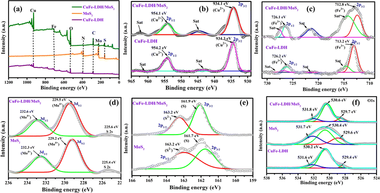 | ||
| Fig. 4 The XPS spectra of CuFe-LDH, MoS2, and CuFe-LDH/MoS2: (a) survey spectra, (b) Cu 2p, (c) Fe 2p, (d) Mo 3d, (e) S 2p and (f) O 1s. | ||
In Fig. 4(d), we offer a comparative analysis of the resolved Mo 3d spectrum, contrasting pure MoS2 with the Mo component within CuFe-LDH/MoS2. Within the Mo XPS peaks of unaltered MoS2, we discerned a division into three peaks, with the two principal peaks situated at 232.6 eV (3d3/2) and 229.5 eV (3d5/2), signifying the Mo4+ oxidation state. Additionally, peaks at 232.3 and 229.2 eV were evident, indicating the presence of the Mo4+ oxidation state and the S 2s state. Furthermore, we scrutinized the high-resolution S 2p spectra of pure MoS2 (Fig. 4(e)), which could be decomposed into two doublet peaks at 161.7 and 163.2 eV, corresponding to the 2p3/2 and 2p1/2 spin states of S 2p, confirming the S2− oxidation state. Likewise, the high-resolution S 2p spectra of CuFe-LDH/MoS2 displayed two doublet peaks at 161.9 and 163.2 eV, attributed to the 2p3/2 and 2p1/2 spin states of S 2p, validating the S2− oxidation state. Fig. S4(a) and (b) (ESI†), which depicts the C1s and N1s spectra, provides compelling evidence for the establishment of a heterojunction between CuFe-LDH and MoS2. These spectra distinctly reveal the presence of C–C and C–N moieties within the structural composition of this heterojunction.41
The XPS spectral findings presented above reveal notable shifts in the BE positions in both neat MoS2 and CuFe-LDH upon the establishment of an S-scheme charge transfer mechanism in CuFe-LDH/MoS2. Specifically, MoS2 experiences a blue shift in BE location, concurrent with a red shift observed in the BE location of CuFe-LDH. These shifts are accredited to the transference of electrons from CuFe-LDH to MoS2, followed by the recombination of the gathered electrons from MoS2 with the h+ within LDH. Consequently, this process leads to an enrichment of the e− density within MoS2 in the nanocomposite, resulting in fewer BEs for Mo and S, respectively. Simultaneously, the diminished e− density within LDH in CuFe-LDH/MoS2 induces an upward shift in the BE positions of Cu, Fe, and O. This reordering of the chemical environment delivers a compelling indication for the presence of a charge-transference-induced electric field and a vigorous electronic interface between LDH and MoS2, facilitated by the creation of an S-scheme mode of charge pair departure. Consequently, the departure of photoinduced exciton pairs becomes more facile at advanced reduction and oxidation potentials, ultimately enhancing the photocatalytic performance.39–41 Moreover, following the hybridization of MoS2 with CuFe-LDH, there is a notable increase in the proportion of active sulfur sites, as evidenced by Fig. 4. This observation aligns with the loading of MoS2 onto CuFe-LDH nanosheets, further supporting the augmentation of sulfur active sites.
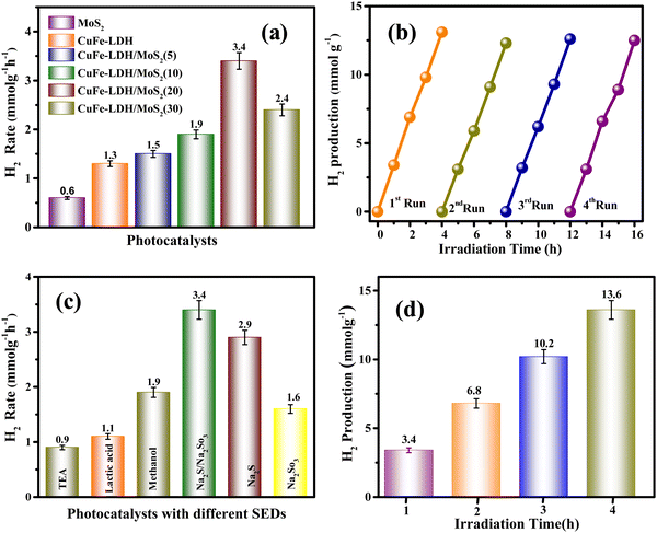
The photocatalytic generation of H2 was evaluated in MoS2, CuFe-LDH, and CuFe-LDH/MoS2-(x) by exposing them to aqueous Na2S and Na2SO3 solution (50 mL) under direct visible light (λ ≥ 400 nm), as represented in Fig. 5(a). In the absence of a catalyst or light, no H2 evolution was observed, underscoring the dependence of photocatalytic H2 creation on the synergistic influence of both the catalyst and light.47–49 CuFe-LDH and MoS2 exhibited H2 formation rates of 1.3 and 0.6 mmol g−1 h−1, respectively. Notably, CuFe-LDH/MoS2-(x), operating through the S-scheme charge-carrier-transference mechanism amid CuFe-LDH and MoS2, exhibited significantly enhanced H2 formation performance compared to the individual CuFe-LDH and MoS2.50 As the weight percentage (wt%) of MoS2 varied from 5 to 30 in CuFe-LDH/MoS2-(x), the H2 formation rate increased from 1.5 mmol g−1 h−1 (CuFe-LDH/MoS2(5)) to 1.9 mmol g−1 h−1 (CuFe-LDH/MoS2(10)) and further to 3.4 mmol g−1 h−1 (CuFe-LDH/MoS2(20)), before decreasing to 2.4 mmol g−1 h−1 (CuFe-LDH/MoS2(30)), functioning optimally when exposed to visible light, indicating its high charge mobility (Table S1, ESI†). In contrast, single MoS2 displayed negligible photocatalytic H2 creation, likely due to inefficient charge separation or poor transport of charge transporters to the H2 creation active sites. The observed enhancements in photocatalytic performance can be attributed to several factors within CuFe-LDH/MoS2(20), including the quantum confinement effects, increased exposure of active edges, and light scattering phenomena resulting from the nanolayered MoS2. These factors are thermodynamically favorable for promoting the H2 creation reaction. However, excessive filling of MoS2 led to a decline in photocatalytic performance. This decline can be attributed to MoS2 acting as a shield within CuFe-LDH/MoS2(20), which hinders the absorption of photons. The overall improvement in photocatalytic actions is primarily ascribed to the establishment of an S-scheme charge flow, achieved through the filling of MoS2 onto CuFe-LDH, as exemplified in the CuFe-LDH/MoS2(20) heterostructure.
Single MoS2 exhibits a negligible amount of photocatalytic H2 production either because of inefficient charge separation or because of the reduced transportation of the charge carriers to the hydrogen evolution active edges. The incremental photocatalytic performances are due to the increase in exposed active edges, quantum confinement, or light scattering effect of nanolayered MoS2 in CuFe-LDH/MoS2, which is thermodynamically feasible for the hydrogen evolution reaction. However, extra loading of MoS2 resulted in the reduction of photocatalytic performance, which is owing to the shielding because of MoS2 in CuFe-LDH/MoS2 that creates hindrance for photon absorption.41 The augmentation in photocatalytic activities is attributed to the heterojunctions with the S-scheme charge existence of flow obtained due to the incorporation of MoS2 on CuFe-LDH as in the CuFe-LDH/MoS2 heterostructure.
The investigation of material recyclability is of paramount importance, considering the common occurrence of reduced catalytic effectiveness upon repeated utilization in a hydrated medium under exposure to normal sunshine or visible light. To assess the long-term photocatalytic constancy and recyclability of a semiconductor, we subjected the CuFe-LDH/MoS2(20) heterostructure to four successive cycles of catalytic reactions for H2 production. Additionally, Fig. 5(b) illustrates the results of catalytic recyclability tests for H2 evolution, conducted over four distinct cycles. Notably, Fig. 5(b) highlights a consistent rate of H2 recyclability throughout the repeated fourth cycle, indicating the high stability of the CuFe-LDH/MoS2(20) material in its photocatalytic H2 evolution activity. This robust performance underscores the material's chemical stability and suitability for clean reusability in the process of photocatalytic H2 formation. As revealed by the powder XRD, it (after the HER) shows weak peak intensity but no significant local structural change in the CuFe-LDH/MoS2(20) catalyst was observed; this could be attributed to the presence of Na in the sample, as Na2S and Na2SO3 are used as SEDs. The decrease in intensity may be related to the occupation of oxygen vacancies by Na ions. XPS results49 are consistent with the XRD findings. As revealed by XPS, it shows nearly the same peaks before and after activity. The additional elemental peak of Na is observed at 1073 eV in the XPS result after activity, as shown in Fig. S5 (ESI†). This data highlights the long-term stability of the catalyst under experimental conditions. To provide a comprehensive overview of the catalytic performance, we present a comparative table (Table S2, ESI†) that juxtaposes the performance of CuFe-LDH/MoS2(20) with materials discussed in the existing literature. Fig. 5(c) illustrates the performance of CuFe-LDH/MoS2(20) concerning H2 production efficiency when employing various sacrificial agents. The hydrogen evolution efficiencies for CuFe-LDH/MoS2(20)/TEA, CuFe-LDH/MoS2(20)/methanol, CuFe-LDH/MoS2(20)/lactic acid, CuFe-LDH/MoS2(20)/Na2S/Na2SO3, CuFe-LDH/MoS2(20)/Na2S, and CuFe-LDH/MoS2(20)/Na2SO3 were found to be 0.9 mmol g−1 h−1, 1.9 mmol g−1 h−1, 1.1 mmol g−1 h−1, 3.4 mmol g−1 h−1, 2.9 mmol g−1 h−1, and 1.6 mmol g−1 h−1, respectively. The maximum effective combination for H2 creation was CuFe-LDH/MoS2(20) in conjunction with Na2S/Na2SO3 is 3.4 mmol g−1 h−1. This outcome is thinkable attributable to the enhanced charge transfer reactions within this system and a reduction in electron–hole recombination. The efficiency of the evolution of H2 was conducted over a time of four hours in Fig. 5(d).
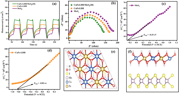
To investigate interfacial transference and departure of photon-generated charge transporters within the photocatalysts, we conducted PEC property tests on MoS2, CuFe-LDH, and CuFe-LDH/MoS2(20). The curves for the transient photocurrent density of the composites are presented in Fig. 6(a). Under irregular light irradiation, the photocurrent responses of all catalysts exhibited variations, reflecting the inherent characteristics of each semiconductor catalyst. Subsequently, because of hole accumulation, the photocurrent density of the composites steadily declined. The comparatively lower photocurrent density observed for MoS2 and CuFe-LDH can be accredited to the pronounced recombination of e− and h+. In contrast, CuFe-LDH/MoS2(20) exhibited the highest photocurrent response compared to MoS2 and CuFe-LDH, indicating that the joining of CuFe-LDH significantly enhances the departure of photogenerated transporters on MoS2. Obviously, the transient photocurrent of the MoS2/CuFe-LDH composite was significantly enhanced. This was because the MoS2/CuFe-LDH composite formed a direct S-scheme heterojunction, which resulted in the CB electrons of MoS2 that transferred to the CuFe-LDH VB recombining with the holes under visible light and realizing the effective separation of the photogenerated electrons and holes. In general, during the photogenerated electron transfer process, the impedance is inversely proportional to the transient photocurrent.40 This was beneficial to improve the photocatalytic H2 evolution activity. This enhanced separation of photogenerated charges, along with the effective suppression of electron–hole recombination, can be attributed to the type-II and S-scheme heterojunction architecture. CuFe-LDH/MoS2(20) thus demonstrates excellent photocatalytic H2 creation activity.
The area of arcs observed in electrochemical impedance spectroscopy (EIS) plots can serve as a valuable metric for investigating the charge transference resistance occurring amid the working electrode and electrolyte. In the context of open circuit potential conditions, the Nyquist plots for our composites are depicted in Fig. 6(b). Notably, due to its limited electric conduction, CuFe-LDH exhibits a bigger arc area in the Nyquist plot. Conversely, CuFe-LDH/MoS2(20) displays a smaller circular arc area, indicative of its enhanced charge transference rate and superior electrical conductivity.51 This improved charge transference rate actively contributes to the acceleration of the photocatalytic reaction rate.
The assessment of CB positions in semiconductor materials is achieved using Mott–Schottky analysis. Both CuFe-LDH and MoS2 display characteristics consistent with n-type semiconductors, as shown in Fig. 6(c) and (d). In contrast, the flat band potentials for CuFe-LDH and MoS2 are measured at −0.25 and −0.83 V, respectively, relative to the standard calomel electrode (SCE).46 The flat band potential (Vfb) of CuFe-LDH and MoS2 is calculated following the (eqn (2)).38
 | (2) |
Typically, in the n-type semiconductors, the CB energy level (ECB) is positioned approximately −0.1 to −0.2 V more negative compared to the flat band potential (Efb). The theoretical ECB values for MoS2 and CuFe-LDH are −0.45 and −1.03 V vs. SCE, respectively. By applying (eqn (3)), the ECB for MoS2 and CuFe-LDH can be crudely assessed as −0.21 and −0.79 V, respectively, relative to the NHE. Comparing the conduction band position of MoS2 (−0.21 V) to that of CuFe-LDH (−0.79 V) with respect to the standard hydrogen electrode, MoS2 displays a relatively more positive nature.50 As a result, the combination of CuFe-LDH and MoS2 found an auspicious thermodynamic path for the transference of photogenerated e−. These findings line up with the data obtained from photoluminescence spectroscopy.
| ENHE = ESCE + 0.241 | (3) |
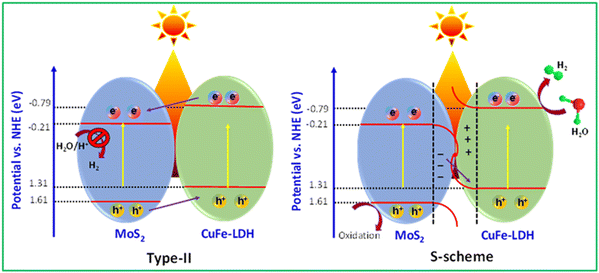
In the realm of photocatalysis employing photocatalytic materials, the route of electron transference is mainly governed by the disparity in Fermi energy levels. MoS2 features an energy band gap (Eg) of around 1.82 eV, along with CB (ECB) and VB (EVB) potentials of −0.21 and 1.61, respectively. Similarly, CuFe-LDH exhibits an Eg of around 2.1 eV, with corresponding ECB and EVB values of −0.79 and 1.31, respectively.52
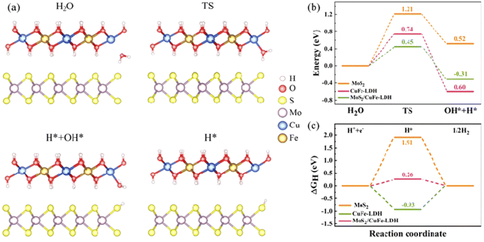
To illuminate the synergistic influences arising from the MoS2/CuFe-LDH interface on catalytic H2 creation, the significant reaction stages on the MoS2 and CuFe-LDH catalysts as well as on the MoS2/CuFe-LDH interface are investigated using DFT calculations. Theoretical frameworks for MoS2 and CuFe-LDH were constructed, aiming to investigate the Gibbs energy in the MoS2/CuFe LDH heterostructure, with their representations illustrated in Fig. 6(e) and (f). Fig. 7(a) provides a representation of the HER kinetics, incorporating both the initial H2O splitting process via a transition state and the succeeding chemisorption of intermediates (H and OH). The splitting of H2O into adsorbed H and OH on MoS2 demands an input of approximately 0.52 eV, rendering it energetically endothermic and encountering a high energy barrier of 1.21 eV, making pure MoS2 thermodynamically unfavorable for this process. In contrast to MoS2, the water dissociation energy barrier decreases to 0.74 eV for CuFe-LDH and 0.45 for the MoS2/CuFe-LDH interface, as shown in Fig. 7(b). This reduction accelerates the sluggish Volmer step and subsidiary energy barrier for OH–H bond breakage, ultimately facilitating water dissociation. Consequently, the hybridization of MoS2 with CuFe-LDH effectively enhances both the thermodynamics and kinetics of the rate-determining step for the H2 evolution reaction (HER), aligning with our experimental findings. In addition to the energy barrier associated with the initial H2O dissociation, the Gibbs free energy (ΔGH) of adsorbed hydrogen holds significant importance. Fig. 7(c) illustrates the ΔGH amid the adsorbed *H atom and gassy H2. It is evident that both MoS2 (1.91 eV) and CuFe-LDH (−0.93 eV) exhibit large ΔGH values, suggesting an unfavorable condition for the release of H2 molecules. Meanwhile, CuFe-LDH/MoS2 shows a smaller ΔGH of 0.26 eV, approximate to the ideal 0 eV, indicating a balanced adsorption strength of H on the surface neither overly strong nor weak thus favoring the H-adsorption and subsequent release of H2 molecules.46 Therefore, the interfacial synergistic effect within CuFe-LDH/MoS2 leads to an auspicious energy barrier during the initial H2O dissociation step, ultimately facilitating the H2 creation.
Based on the findings, we were able to ascertain the CB and VB energy levels for CuFe-LDH and MoS2, as presented in Fig. 8. These two semiconductor materials, forming heterojunctions, can be categorized as either type II heterojunctions or S-scheme heterojunctions.39,51 For the hypothetical scenario of a type II heterojunction, photogenerated e− and h+ would migrate to the places corresponding to CuFe-LDH and the VB and CB of MoS2, respectively. However, it's worth noting that the CB energy level of MoS2, is relatively low, approximately −0.21 eV, which provides an adequate driving force for hydrogen production. But the MoS2 single unit cell possesses a negligible amount of hydrogen generation efficiency due to the lower charge transportation efficiency. Obviously, compared with that in MoS2, the peak position of S 2p in CuFe-LDH/MoS2 shifted to a higher position, and the peak position of Cu 2p and Fe 2p in CuFe-LDH/MoS2 shifted to a lower position. These observations confirm the formation of an S-scheme heterojunction, indicating favorable electron transfer from MoS2 to CuFe-LDH.53–57 In this S-scheme heterojunction, when the photocatalysts are in near contact, e− naturally transfers from CuFe-LDH to MoS2 due to coulombic forces. Owing to the differing +Ve and −Ve characteristics of the two photocatalysts, an internal electric arena forms at the interface, leading to band bending resulting from the transference and buildup of e−. When exposed to visible light, the e− in the MoS2 CB is associated with the h+ in the CuFe-LDH VB, effectively eliminating surplus e− and h+. Consequently, the hydrogen creation process takes place at the CuFe-LDH CB, with the reaction occurring at the MoS2 VB.
According to the foregoing findings, the MoS2/CuFe-LDH catalyst is suitable for photocatalytic activity. The following factors contribute to the enhanced photocatalytic activity and stability: (i) UV DRS and PL studies show that MoS2 ions in the CuFe-LDH catalyst boosted light absorption and decreased photogenerated ion recombination, respectively.54,58 (ii) The sheet like-structure encourages interaction between the CuFe-LDH and MoS2 catalyst and the reaction solution, resulting in rapid charge transport during the photocatalytic process. The inclusion of CuFe-LDH to MoS2 frames adds more active sites, which helps with photocatalysis. (iii) DFT calculations also show a decline in the band gap of MoS2 following doping with CuFe-LDH atoms, indicating increased electron conductivity and photocatalytic activity of MoS2/CuFe-LDH. Overall, the MoS2/CuFe-LDH hybrid has been considered a very efficient and stable photocatalyst for hydrogen production due to the synergetic effects of highly active CuFe-LDH and the sheet-like constitution of MoS2.59,60 To gain further insights into the mechanism of photocatalytic H2 generation and the separation of photogenerated electrons and holes in these MoS2/CuFe-LDH heterostructures, we also performed EIS, PL emission spectroscopy, and transient photocurrent measurements. In that, EIS analysis was employed to evaluate the internal resistance of the charge-transfer process of the samples.
Conclusion
The CuFe-LDH/MoS2 composites was successfully synthesized via a hydrothermal method, establishing an S-scheme heterojunction by the compatible band structures and electron transfer properties of MoS2 and CuFe-LDH. The intimate proximity of MoS2 and CuFe-LDH results in efficient charge transfer and a significant enhancement of photogenerated carrier transfer rates due to the generated internal electric field. This successful coupling not only expedites photogenerated carrier separation but also minimizes electron transfer resistance, preventing charge recombination between CuFe-LDH and MoS2, and ultimately boosting hydrogen production efficiency. In comparison to CuFe-LDH and MoS2, the CuFe-LDH/MoS2 composite exhibited the highest photocatalytic hydrogen production, yielding 3.4 mmol g−1 h−1 in 4 hours and maintaining good stability over a 16-hour cycling test. In summary, this study offers a novel understanding of the building of S-type heterojunctions in 2D/2D spatially structured photocatalysts.Conflicts of interest
The authors declare that they have no known competing financial interests or personal relationships that could have appeared to influence the work reported in this paper.Acknowledgements
This work is supported by the CSIR-IICT (MLP-0082) and DST/TMD/HFC/2k18/60, DST INSPIRE fellowship (IF 180789). CSV thanks DST and SPS CSIR for research funding and AcSIR for their PhD enrolment. We are thankful to Dr D. Srinivasa Reddy, Director, Dr A. Gangagni Rao, HOD, DEEE in CSIR-IICT for all research facilities. BMA expresses his gratitude to HPC center, IIT Kanpur for providing the computational facilities. CSIR-IICT Communication no: IICT/Pubs./2023/367.References
- Y. Wang, H. Suzuki, J. Xie, O. Tomita, D. J. Martin, M. Higashi, D. Kong, R. Abe and J. Tang, Mimicking Natural Photosynthesis: Solar to renewable H2fuelsynthesis by Z-Scheme water splitting systems, Chem. Rev., 2018, 118, 5201–5241 CrossRef CAS PubMed.
- I. Mondal, A. Mahata, H. Kim, U. Pal, F. D. Angelis and J. Y. Park, A combined experimental and theoretical approach revealing a direct mechanism for bifunctional water splitting on doped copper phosphide, Nanoscale, 2020, 12, 17769–17779 RSC.
- S. Gonuguntla, R. Kamesh, U. Pal and D. Chatterjee, Dye sensitization of TiO2 relevant to photocatalytic hydrogen generation, J. Photochem. Photobiol., 2023, 57, 100621 CrossRef CAS.
- C. S. Gopinath and N. Nalajala, A scalable and thin film approach for solar hydrogen generation: a review on enhanced photocatalytic water splitting, J. Mater. Chem. A, 2021, 9, 1353–1371 RSC.
- J. Wang, G. Wang, B. Cheng, J. Yu and J. Fan, Sulfur-doped g-C3N4/TiO2 S-scheme heterojunction photocatalyst for Congo Red Photodegradation, Chin. J. Catal., 2021, 42, 56–68 CrossRef CAS.
- A. Gautam, S. Sk and U. Pal, Recent advances in solution assisted synthesis of transition metal chalcogenides for photo-electrocatalytic hydrogen evolution, Phys. Chem. Chem. Phys., 2022, 24, 20638–20673 RSC.
- L. Mohapatra and K. Parida, A review on the recent progress, challenges, and perspective of layered double hydroxides as promising photocatalysts, J. Mater. Chem. A, 2016, 4, 10744–10766 RSC.
- M. Laipan, H. Fu, R. Zhu1, L. Sun, J. Zhu and H. He, Converting Spent Cu/Fe Layered Double Hydroxide into Cr(VI) Reductant and Porous Carbon Material, Sci. Rep., 2017, 7, 1–11 CrossRef CAS PubMed.
- I. Mondal and U. Pal, Synthesis of MOF templated Cu/CuO@TiO2 nanocomposites for synergistic hydrogen production, Phys. Chem. Chem. Phys., 2016, 18, 4780–4789 RSC.
- W. Jiang, X. Zong, L. An, S. Hua, X. Miao, S. Luan, Y. Wen, F. F. Tao and Z. Sun, Consciously Constructing Heterojunction or Direct Z-Scheme Photocatalysts by Regulating Electron Flow Direction, ACS Catal., 2018, 8, 2209–2217 CrossRef CAS.
- W. Yin, L. Bai, Y. Zhu, S. Zhong, L. Zhao, Z. Li and S. Bai, Embedding Metal in the Interface of a p–n Heterojunction with a Stack Design for Superior Z-Scheme Photocatalytic Hydrogen Evolution, ACS Appl. Mater. Interfaces, 2016, 8, 23133–23142 CrossRef CAS PubMed.
- C. S. Vennapoosa, A. Karmakar, Y. T. Prabhu, B. M. Abraham, S. Kundu and U. Pal, Rh-doped ultrathin NiFeLDH nanosheets drive efficient photocatalytic water splitting, Int. J. Hydrogen Energy, 2023, 52, 371–384 CrossRef.
- S. Sk, R. Madhu, D. S. Gavali, V. Bhasin, R. Thapa, S. N. Jha, D. Bhattacharyya, S. Kundu and U. Pal, An ultrathin 2D NiCo-LDH nanosheet decorated NH2-UiO-66 MOF-nanocomposite with exceptional chemical stability for electrocatalytic water splitting, J. Mater. Chem. A, 2023, 11, 10309–10318 RSC.
- M. He, S. Hu, C. Feng, H. Wu, H. Liu and H. Mei, Interlaced rosette-like MoS2/Ni3S2/NiFe-LDH grown on nickel foam: a bifunctional electrocatalyst for hydrogen production by urea-assisted electrolysis, Int. J. Hydrogen Energy, 2020, 45, 23–35 CrossRef CAS.
- I. Mondal, S. Gonuguntla and U. Pal, Photo induced fabrication of Cu/TiO2 core-shell heterostructure derived from Cu-MOF for solar hydrogen generation: the size of the Cu nanoparticle matters, J. Phys. Chem. C, 2019, 123, 26073–26081 CrossRef CAS.
- M. Gong, Y. Li, H. Wang, Y. Liang, J. Z. Wu, J. Zhou, J. Wang, T. Regier, F. Wei and H. Dai, An Advanced Ni–Fe Layered Double Hydroxide Electrocatalyst for Water Oxidation, J. Am. Chem. Soc., 2013, 135, 8452–8455 CrossRef CAS PubMed.
- M. Gong, Y. Li, H. Wang, Y. Liang, J. Z. Wu, J. Zhou, J. Wang, T. Regier, F. Wei and H. Dai, An Advanced Ni–Fe Layered Double Hydroxide Electrocatalyst for Water Oxidation, J. Am. Chem. Soc., 2013, 135, 8452–8455 CrossRef CAS PubMed.
- D. Huang, J. Ma, L. Yu, D. Wu, K. Wang, M. Yang, D. Papoulis and S. Komarneni, AgCl and BiOCl Composited with NiFe-LDH for Enhanced Photo-Degradation of Rhodamine B, Sep. Purif. Technol., 2015, 156, 789–794 CrossRef CAS.
- R. Boppella, C. H. Choi, J. Moon and D. Ha Kim, Spatial charge separation on strongly coupled 2D-Hybrid of rGO/La2Ti2O7/NiFe-LDH heterostructures for highly efficient noble metal free photocatalytic hydrogen generation, Appl. Catal., B, 2018, 239, 178–186 CrossRef CAS.
- S. C. Shit, I. Mondal, P. Saikiran, L. Bai, J. Y. Park and J. Mondal, MOF-derived bifunctional iron oxide and iron phosphide nanoarchitecture photo electrode for neutral water splitting, ChemElectroChem, 2018, 5, 2842–2849 CrossRef CAS.
- L. Liu, S. Li, Y. An, X. Sun, H. Wu, J. Li, X. Chen and H. Li, Hybridization of nan diamond and CuFe-LDH as heterogeneous photo activator for visible-light driven photo-Fenton reaction: photocatalytic activity and mechanism, Catalysts, 2019, 9, 118–129 CrossRef.
- Y. Hou, R. M. Lohe, J. Zhang, S. H. Liu, X. D. Zhuang and X. L. Feng, Vertically oriented cobalt selenide/NiFe layered-double hydroxide nanosheets supported on exfoliated graphene foil: an efficient 3D electrode for overall water splitting, Energy Environ. Sci., 2016, 9, 478–483 RSC.
- X. L. Ma, X. M. Li, A. D. Jagadale, X. G. Hao, A. Abudul and G. Q. Guan, Fabrication of Cu(OH)2@NiFe-layered double hydroxide catalyst array for electrochemical water splitting, Int. J. Hydrogen Energy, 2016, 41, 14553–14561 CrossRef CAS.
- A. Kumaresan, S. Yang, K. Zhao, N. Ahmad, J. Zhou, Z. Zheng, Y. Zhang, Y. Gao, H. Zhou and Z. Tang, Facile development of CoAl-LDHs/RGO nanocomposites as photocatalysts for efficient hydrogen generation from water splitting under visible-light irradiation, Inorg. Chem. Front., 2019, 6, 1753–1760 RSC.
- J. Zhang, Q. Zhu, L. Wang, M. Nasir, S.-H. Cho and J. Zhang, g-C3N4/CoAl-LDH 2D/2D hybrid heterojunction for boosting photocatalytic hydrogen evolution, Int. J. Hydrogen Energy, 2020, 45, 21331–21340 CrossRef CAS.
- Z. Jin, X. Wang, Y. Wang, T. Yan and X. Hao, Snowflake-like Cu2S coated with NiAl-LDH forms a p−n heterojunction for efficient photocatalytic hydrogen evolution, ACS Appl. Energy Mater., 2021, 4, 14220–14231 CrossRef CAS.
- I. Mondal, S. Gonuguntla and U. Pal, Photoinduced fabrication of Cu/TiO2core−shell heterostructures derived from Cu-MOF for solar hydrogen generation: the size of the Cu nanoparticle matters, J. Phys. Chem. C, 2019, 123, 26073–26081 CrossRef CAS.
- G. Ye, Y. Gong, J. Lin, B. Li, Y. He, S. T. Pantelides, W. Zhou, R. Vajtai and P. M. Ajayan, Defects engineered monolayer MoS2 for improved hydrogen evolution reaction, Nano Lett., 2016, 16, 1097–1103 CrossRef CAS PubMed.
- G. Swain, S. Sultana, J. Moma and K. Parida, Fabrication of hierarchical two-dimensional MoS2 nanoflower decorated upon cubic CaIn2S4 micro flowers: facile approach to construct novel metal-free p–n heterojunction semiconductors with superior charge separation efficiency, Inorg. Chem., 2018, 57, 10059–10071 CrossRef CAS PubMed.
- C. Feng, Z. Chen, J. Hou, J. Li, X. Li, L. Xu, M. Sun and R. Zeng, Effectively enhanced photocatalytic hydrogen production performance of one-pot synthesized MoS2 clusters/CdS nanorod heterojunction material under visible light, Chem. Eng. J., 2018, 345, 404–413 CrossRef CAS.
- A. Tiwari, A. Gautam, S. Sk, D. S. Gavali, R. Thapa and U. Pal, Controlled loading of MoS2 on hierarchical porous TiO2 for enhanced photocatalytic hydrogen evolution, J. Phys. Chem. C, 2021, 125(22), 11950–11962 CrossRef CAS.
- A. Gautam, Y. T. Prabhu and U. Pal, Efficient charge transfer on the tunable morphology of TiO2/MoS2 photocatalyst for an enhanced hydrogen production, New J. Chem., 2021, 45, 10257–10267 RSC.
- X. Liu, B. Wang, M. Liu, S. Liu, W. Chen, L. Gao and X. Li, In situ growth of vertically aligned ultrathin MoS2 on porous g-C3N4 for efficient photocatalytic hydrogen production, Appl. Surf. Sci., 2021, 554, 149617–149624 CrossRef CAS.
- Y. T. Prabhu, V. N. Rao, M. V. Shankar, B. Sreedhar and U. Pal, The facile hydrothermal synthesis of CuO@ZnO heterojunction nanostructures for enhanced photocatalytic hydrogen evolution, New J. Chem., 2019, 43, 6794–6805 RSC.
- A. Gautam, S. Sk, A. Jamma, B. M. Abraham, M. Ahmadipourd and U. Pal, Colloidal synthesis of a heterostructured CuCo2S4/g-C3N4/In2S3 nanocomposite for photocatalytic hydrogen evolution, Energy Adv., 2023, 2, 1512–1520 RSC.
- C. Zhao, X. Li, L. Yue, S. Yuan, X. Ren, Z. Zeng, X. Hu, Y. Wu and Y. He, One-step preparation of novel Bi–Bi2O3/CdWO4 Z-scheme heterojunctions with enhanced performance in photocatalytic NH3 synthesis, J. Alloys Compd., 2023, 968, 171956 CrossRef CAS.
- Y. Jiuheng, C. Sumin, L. Baojun and T. Wei, Construction of MoS2/NiFe-Ni foam p–n heterojunction as Photoanode for tetracycline degradation and simultaneous cathodic hydrogen evolution, J. Environ. Chem. Eng., 2022, 10, 108437 CrossRef.
- M. Laipan, H. Fu, R. Zhu1, L. Sun, J. Zhu and H. He, Converting Spent Cu/Fe Layered Double Hydroxide into Cr(VI) Reductant and Porous Carbon Material, Sci. Rep., 2017, 7, 1–11 CrossRef CAS PubMed.
- X. Liu, J. Xu, L. Ma, Y. Liu and L. Hua, Nano-flower S-scheme heterojunction NiAl-LDH/MoS2 for enhancing photocatalytic hydrogen production, New J. Chem., 2022, 46, 228–238 RSC.
- Y. Sun, X. Wang, Q. Fu and C. Pan, Construction of Direct Z-Scheme Heterojunction NiFe-Layered Double Hydroxide (LDH)/Zn0.5Cd0.5S for Photocatalytic H2 Evolution, ACS Appl. Mater. Interfaces, 2021, 13, 39331–39340 CrossRef CAS PubMed.
- S. Nayak, G. Swain and K. Parida, Enhanced Photocatalytic Activities of RhB Degradation and H2 Evolution from in Situ Formation of the Electrostatic Heterostructure MoS2/NiFe LDH Nanocomposite through the Z-Scheme Mechanism via p−n Heterojunctions, ACS Appl. Mater. Interfaces, 2019, 11, 20923–20942 CrossRef CAS PubMed.
- M. Rong, F. Yang, C. Yu, S. Wang, H. Zhong and Z. Cao, MoS2/CoAl-LDH heterostructure for enhanced efficient of oxygen evolution reaction, Colloids Surf., A, 2020, 607, 125419 CrossRef CAS.
- J. Shen, J. Liang, X. Fu, Y. Jiang, S. Yan, H. He and X. Ren, Facile Synthesis of CuMgFe Layered Double Hydroxides for Efficient Catalytic Phenol Hydroxylation under Mild Conditions, ChemistrySelect, 2020, 5, 2835–2841 CrossRef CAS.
- C. S. Vennapoosa, S. Varangane, B. M. Abraham, V. Perupogu, S. Bojja and U. Pal, Controlled photoinduced electron transfer from g-C3N4 to CuCdCe-LDH for efficient visible light hydrogen evolution reaction, Int. J. Hydrogen Energy, 2022, 47, 40227–40241 CrossRef CAS.
- S. Nayak, L. Mohapatra and K. Parida, Visible light-driven novel g-C3N4/NiFe-LDH composite photocatalyst with enhanced photocatalytic activity towards water oxidation and reduction reaction, J. Mater. Chem. A, 2015, 3, 18622–18635 RSC.
- H. Sun, W. Zhang, J. G. Li, Z. Li, X. Ao, K. H. Xue, K. K. Ostrikov, J. Tang and C. Wang, Rh-engineered ultrathin NiFe-LDH nanosheets enable highly-efficient overall water splitting and urea electrolysis, Appl. Catal., B, 2021, 284, 119740 CrossRef CAS.
- T. Liu, K. Yang, H. Gong and Z. Jin, Visible-light driven S-scheme Mn0.2Cd0.8S/CoTiO3 heterojunction for photocatalytic hydrogen evolution, Renewable Energy, 2021, 173, 389–400 CrossRef CAS.
- J. Tao, X. Yu, Q. Liu, G. Liu and H. Tang, Internal electric field induced S-scheme heterojunction MoS2/CoAl LDH for enhanced photocatalytic hydrogen evolution, J. Colloid Interface Sci., 2021, 585, 470–479 CrossRef CAS PubMed.
- C. S. Vennapoosa, S. Gonuguntla, S. Sk, B. M. Abraham and U. Pal, Ternary Cu(OH)2/P(C3N4)/MoS2 nanostructures for photocatalytic hydrogen production, ACS Appl. Nano Mater., 2022, 5, 4848–4859 CrossRef CAS.
- Y. Zou, D. Maa, D. Suna, S. Mao, C. Heb, Z. Wang, X. Jia and J. W. Shi, Carbon nanosheet facilitated charge separation and transfer between molybdenum carbide and graphitic carbon nitride toward efficient photocatalytic H2 production, Appl. Surf. Sci., 2019, 473, 91–100 CrossRef CAS.
- C. Zheng, K. Kang, Y. Xie, X. Yang, L. Lana, H. Song and S. Bai, Competitive adsorption and selectivity of water vapor/R134a on activated carbon for indoor air purification, Sep. Purif. Technol., 2023, 317, 123741 CrossRef CAS.
- Y. Zhang and Z. Jin, Boosting Photocatalytic Hydrogen Evolution Achieved by NiSx Coupled with g-C3N4@ZIF-67 Heterojunction, J. Phys. Chem. C, 2019, 123, 18248–18263 CrossRef CAS.
- S. Yuan, J. Wang, C. Zhao, L. Yue, X. Ren, Z. Zeng, X. Hu, Y. Wu and Y. He, S-scheme Bi2O3/CdMoO4 hybrid with highly efficient charge separation for photocatalytic N2 fixation and tetracycline Degradation: Fabrication, catalytic Optimization, physicochemical studies, Sep. Purif. Technol., 2023, 325, 124665 CrossRef CAS.
- C. S. Vennapoosa, S. Varangane, S. Gonuguntla, B. M. Abraham, M. Ahmadipour and U. Pal, S-Scheme ZIF-67/CuFe-LDH Heterojunction for High-Performance Photocatalytic H2 Evolution and CO2 to MeOH Production, Inorg. Chem., 2023, 62, 16451–16463 CrossRef CAS PubMed.
- M. Hao, D. Wei and Z. Li, Rational Design of an Efficient S-Scheme Heterojunction of CdS/Bi2WO6–S Nanocomposites for Photocatalytic CO2 Reduction, Energy Fuels, 2022, 36, 11524–11531 CrossRef CAS.
- B. Su, H. Huang, Z. Ding, M. B. J. Roeffaers, S. Wang and J. Long, S-scheme CoTiO3/Cd9.51Zn0.49S10 heterostructures for visible-light driven photocatalytic CO2 reduction, J. Mater. Sci. Technol., 2022, 124, 164–170 CrossRef CAS.
- S. Liu, K. Wang, M. Yang and Z. Jin, Rationally Designed Mn0.2Cd0.8S@CoAl-LDH S-Scheme Heterojunction for Efficient Photocatalytic Hydrogen Production, Acta Phys.-Chim. Sin., 2022, 38, 2109023 Search PubMed.
- K. Bhunia, M. Chandra, S. Khilari and D. Pradhan, Bimetallic PtAu alloy nanoparticles-integrated g-C3N4 Hybrid as a efficient photocatalyst for water-to-hydrogen conversion, ACS Appl. Mater. Interfaces, 2019, 11, 478–488 CrossRef CAS PubMed.
- S. Li, M. Cai, Y. Liu, C. Wang, K. Lv and X. Chen, S-Scheme photocatalyst TaON/Bi2WO6 nanofibers with oxygen vacancies for efficient abatement of antibiotics and Cr(VI): Intermediate eco-toxicity analysis and mechanistic insights, Chin. J. Catal., 2022, 43, 2652–2664 CrossRef CAS.
- Y. Yang, X. Gu, K. Gong, S. Meng, J. Lei, X. Zheng, Y. Feng and S. Chen, Revealing the charge transfer mechanism and assessing product toxicity in the 2D/1D Bi2O2CO3/Bi8(CrO4)O11 heterostructure system, Environ. Sci.: Nano, 2023, 10, 1867–1882 RSC.
Footnote |
| † Electronic supplementary information (ESI) available. See DOI: https://doi.org/10.1039/d3ma00881a |
| This journal is © The Royal Society of Chemistry 2024 |

