
 Open Access Article
 This Open Access Article is licensed under a
 Creative Commons Attribution 3.0 Unported Licence
Trace element analysis in lithium matrices using micro-discharge optical emission spectroscopy†
Bastian
Wiggershaus
 a,
Miisamari
Jeskanen
b,
Aappo
Roos
b,
Carla
Vogt
*a and
Toni
Laurila
b
a,
Miisamari
Jeskanen
b,
Aappo
Roos
b,
Carla
Vogt
*a and
Toni
Laurila
b
aTU Bergakademie Freiberg, Institute of Analytical Chemistry, Lessingstraße 45, 09599 Freiberg, Germany. E-mail: Carla.Vogt@chemie.tu-freiberg.de
bSensmet Oy, Customer Application Center, Otakaari 7, 02150 Espoo, Finland
First published on 19th March 2024
Abstract
The increasing demand for high purity battery elements and the necessity to reliably determine trace concentrations of impurity metals have triggered recent development of new analytical methods. Both in battery metal production and recycling there is a growing need for new fast, precise and easy-to-use analytical methods, especially for the on-line and on-site analysis of lithium salt solutions, whose derivative products are used in the battery industry. Typically used established techniques, such as ICP-OES or ICP-MS, are usually limited to laboratory use due to high plasma gas flow rates and power consumption, making them unsuitable for real-time analysis and monitoring of industrial processes on-site. Therefore, a fast and precise on-site method which allows trace element analysis would be preferable. Here we have investigated the potential of micro-discharge optical emission spectroscopy (μDOES) for the given challenge of on-line quantification of impurity metals in lithium matrices. The technology is based on a micro-plasma, which is directly created inside an aqueous sample without any carrier gas by using electrodes and high voltage pulses. In this study, the impurity elements Na, K, Al, Fe and Zn were simultaneously measured both in lithium carbonate and lithium hydroxide solutions. For this purpose, the lithium concentrations were varied between 0.3 and 2 mg L−1 and those of the contaminants between 0 and 50 μg L−1. Calibration series and long-term stability measurements were carried out, whereby various parameters such as the plasma discharge energy, signal integration setting and sample electrical conductivity were optimised. Micro-discharge optical emission spectroscopy proved to be useful for the fast and precise main component and trace analysis of saline solutions. A relative standard deviation of 3% was achieved for the lithium concentration in long-term measurements over 9 h. For the trace impurity metals (Na, K, Al, Fe, and Zn) high coefficients of determination (R2 > 0.99) and limits of detection in the low μg L−1-region, comparable to ICP-OES, were obtained. Multi-linear regression models were used to correct for cross-element correlations that may occur at increasing lithium concentrations due to ionisation effects. Industrial process samples were measured on-site and the results were validated using laboratory ICP-OES.
Introduction
Lithium – resources, properties and applications
Lithium is an essential element for the ongoing green energy transition towards renewable energies, green chemistry and other future technologies. It is used in a wide variety of applications, has high economic importance and is therefore considered a critical metal.1,2 The most important fields of application include batteries for mobile devices,3,4 components for electric cars3,4 and grid storage applications.4 It is estimated that batteries account for 74% of the global end-use lithium market, followed by ceramics and glasses with about 14%.4 Lithium is especially suited for use in batteries due to its very high specific capacity of 3.86 A h g−1, resulting from the fact that it has a very low electrode potential (−3.04 V) and is the lightest metal.5 The most important raw material sources for lithium are brine lake deposits and pegmatites. The former are found particularly in Bolivia, Chile and Argentina, and the latter in the Greenbushes in Australia.6 In 2022, the identified total worldwide lithium resources were estimated to be about 89 Mt.4 The production in 2021 exceeded 100![[thin space (1/6-em)]](https://www.rsc.org/images/entities/char_2009.gif) 000 t.4 Depending on the lithium raw material, various processing methods and steps have to be used to obtain a pure end product, which is usually Li2CO3 or LiOH.7 To ensure properly running production, accompanying analytics of the whole process chain are necessary. This includes the analysis of raw materials, intermediates and end products. In this specific case, the analysis of other main/minor components or impurities such as Na, K, Al, Fe and Zn in addition to lithium is required. These elements may be present at varying concentrations in the raw material and must be removed during the process. Furthermore, process analyses must be carried out as quickly as possible and with a high degree of accuracy.
000 t.4 Depending on the lithium raw material, various processing methods and steps have to be used to obtain a pure end product, which is usually Li2CO3 or LiOH.7 To ensure properly running production, accompanying analytics of the whole process chain are necessary. This includes the analysis of raw materials, intermediates and end products. In this specific case, the analysis of other main/minor components or impurities such as Na, K, Al, Fe and Zn in addition to lithium is required. These elements may be present at varying concentrations in the raw material and must be removed during the process. Furthermore, process analyses must be carried out as quickly as possible and with a high degree of accuracy.
Micro-plasmas as an alternative
Although established techniques such as ICP-OES or ICP-MS are primarily used for the analysis of such lithium containing solutions, they have some limitations such as a high consumption of gas for plasma creation or power and are therefore usually limited to off-line laboratory use,8 making them time-consuming techniques and unsuitable for real-time on-site analysis of industrial processes. In addition, high salt loads may cause memory problems, clogging of nebulizers and non-linear response in the calibration process. Even though microwave induced plasma optical emission spectrometry (MIP-OES) replaces argon with nitrogen and offers similar performance to ICP-OES,9 matrix effects related to easily ionisable elements such as Li or Na can be intense10 and the same disadvantages in terms of automated on-site suitability occur. These limitations can be overcome by the use of micro-plasmas, which are a special form of electrical discharge characterized by at least one dimension being in the sub-millimetre range.11 In general, they are generated by applying a high voltage to electrodes or by focusing a high power laser into the discharge medium.11 Micro-plasmas typically have beneficial features such as small size, operation under atmospheric pressure and low power consumption.12 They can be electrically generated using a wide choice of instrumentation using direct current (dc) and pulsed direct current or alternating current (ac).11 A variety of micro-plasma techniques and applications have been reported in the literature. One development is glow discharge, whereby plasma is generated between thin-film and other electrodes and expands depending on the voltage, carrier gas flow and electrode design.8 Needle electrodes can also form a stable plasma in the form of a point discharge13 and are frequently used.14–17 Micro-hollow-cathode discharge (MHC) is characterized by micro-discharges that are generated in spatially limited cavities18 and is in principle the miniaturized version of the classic hollow cathode discharge.19 Capillary tubes as hollow cathodes with internal diameters of a few hundred micrometres can be regarded as a further development of MHC20 and have been used, for example, in the analysis of Hg and Cd in human blood.21 A low-frequency micro-plasma can be generated by a dielectric barrier placed between two electrodes whereby a discharge takes place on the surface of the dielectric as a result of the potential difference.22 The use of an activated carbon electrode tip as a solid carrier has been applied to pre-concentrate heavy metals in water. The carbon electrode tips were dried and subsequently used as an inner electrode to generate the micro-plasma.23 High-frequency micro-plasmas can be capacitively coupled,24,25 inductively coupled26–31 or microwave induced.32,33 Furthermore, there are developments in the field of micro-plasma induced vapor generation,34 which can be coupled to various analytical methods such as ICP-OES.35 An ac-driven micro-plasma has been used as an excitation source integrated using a pneumatic micro nebulizer36 and gas bubbles have been created to assist in the generation of underwater electric sparks.37–39 All the methods mentioned have in common that gases such as He, Ne, Ar or N2 were used to generate the micro-plasma or transport analytes. Although gas consumption is low due to miniature size, the complete elimination of carrier gas would be the most economical option. At this point, the idea of generating the plasma directly in the liquid sample without any carrier gas comes into play. A typical method of excitation is the discharge of a capacitor with the aid of a short-time switch that generates pulsed discharges in the microsecond range in pin-to-pin or pin-to-plate configurations. These in-liquid corona discharges are a partial breakdown, whereby a conductive channel between the two metal electrodes is not achieved in most cases.40 It is generally assumed that micro-discharges are generated by pre-existing bubbles or bubbles that are created in situ by applying high voltage.41 The discharge of an electrolyte solution in a capillary that formed a gas bubble through two platinum electrodes at a voltage of over 1 kV was investigated and the system was successfully used to determine water hardness.42 Furthermore, studies have been carried out to determine the influence of various parameters such as conductivity,43 pH and polarity,44 using nanosecond pulsed discharges45–48 or to perform the analysis of reactive species.49–51 Furthermore, underwater plasmas are used in water treatment, such as the removal of chlorine-containing volatile organic compounds,47 or wet welding.52 Liquid electrodes have also been used for the analysis of solutions, whereby the solution itself serves as an electrode and is usually connected to another electrode via an air gap.53,54 In solution-cathode glow discharge (SCGD), the sample is transported through a glass pipette via a pump and overflows the tip into a waste reservoir with a grounded graphite electrode. The overflow is essential to creating an electrical connection between the graphite electrode and the solution at the tip. An electrode, e.g. made of titanium, with positive potential is placed above the solution. The discharge is then initiated by bringing the anode to approx. 1 mm distance from the solution and applying a potential of 1–2 kV.55 Although some studies have been reported on micro-plasma generation directly in aqueous solutions, real-world demonstrations where a micro-plasma system has been employed for quantitative real-time analysis over long periods of time are still very limited. A candidate is micro-discharge optical emission spectroscopy. Compared to most existing micro-plasma techniques, it is distinguished by the fact that the micro-plasma is directly generated in the aqueous solution using electrodes and applying high voltage pulses without the necessity of any carrier gas such as argon. Contrary to the well-known SCGD, both electrodes are located inside the sample solution (without an air gap) and no waste reservoir is needed to establish an electrical connection. In addition to similarities with classical ICP-OES, which is considered the golden standard for many industrial applications where simultaneous determination of a number of elements and high sensitivity are required and therefore serves as the benchmark, there are potential advantages to the method for industrial process monitoring applications. Therefore, the aim of this study was to investigate the applicability of micro-discharge optical emission spectroscopy to the analysis of the trace elements Na, K, Al, Fe and Zn in lithium containing solutions and to examine analytical performance such as the linear range as well as the long-term stability of the method. As matrices, lithium carbonate (Li2CO3) and lithium hydroxide (LiOH), both highly relevant to the battery industry, were used. Various parameters such as the plasma discharge energy, spectrometer integration setting and sample electrical conductivity were varied.Micro-discharge optical emission spectroscopy
The method is based on optical emission spectroscopy where excited atoms and ions emit electromagnetic radiation at their characteristic wavelengths. Contrary to conventional ICP-OES, the plasma is directly generated inside the aqueous sample without any carrier gas such as argon. For this purpose, the sample is introduced into a measurement cell, which is equipped with two rod electrodes with a diameter of approx. 1 mm.56,57 Depending on the required performance, different electrode configurations and materials such as tungsten or glassy carbon can be used. Fig. 1 illustrates the operation principle. Using high voltage electronics consisting of a capacitor bank, switch card and ballast, a high electrical power of up to 1–2 kW is directed into a small volume of less than 1 mm3 around the cathode placed inside the sample-filled measurement cell.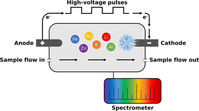 | ||
| Fig. 1 By applying high-voltage pulses to the electrodes, a micro-plasma with an electron temperature of approx. 10000 K is generated by a corona discharge at the cathode directly inside the liquid sample. | ||
By applying high-voltage pulses to the electrodes, a micro-plasma is generated at the cathode directly inside the liquid sample. The micro-plasma is formed by a corona discharge and can be characterized as a non-equilibrium water vapor plasma consisting mainly of H+, OH+ and e−. Using Boltzmann's plot technique an electron temperature of approx. 10000 K in the plasma has typically been determined. As a result, molecules are dissociated into atoms and the atoms are subsequently excited in the small volume around the cathode. The emitted light is then transferred to a spectrometer via an optical fibre cable whereby, similar to SCGD,58 predominantly spectra with neutral atomic lines are obtained. During a single analytical measurement, typically 1000–3000 of approx. 1 ms long micro-plasma pulses are generated and averaged. Depending on the application, various parameters such as electrical sample conductivity, plasma discharge energy or electrode material can be adapted. Additionally, there are several options for signal processing such as the integration setting of the spectrometer.
Experimental
Instrumentation
The experiments were carried out using a μDOES® Online Multi-Metal Process Liquid Analyser (Sensmet Oy, Finland). The analyser was equipped with a tungsten cathode (99.95%) and a glassy carbon anode (99.99%) with an electrode distance of 2 cm as well as Teflon sample tubing. The spectrometer unit employs Czerny–Turner design with CMOS sensors to cover a wavelength range from approx. 200 to 840 nm at a resolution of 0.1 nm, whereby the entire spectrum is always acquired during a measurement. For analysis, interference-free emission lines were selected for each element. A total of 2500 plasma pulses were generated for each measurement, consisting of 50 repeats with 50 pulses each. Based on preliminary investigations, four different parameter settings (A–D) were chosen. To optimise the analysis further, various parameters such as the plasma discharge energy, electrical conductivity of the sample and spectrometer integration time settings were varied, whereby the settings differed in at least one parameter (e.g. A and C in conductivity). In the case of the integration setting, it is possible to either integrate the spectral signal being emitted from single plasma pulses and average over all pulses or integrate over an entire pulse series of 50 pulses and average all series. The “single pulse” (1 pulse) and “pulse series” (50 pulses) integration represent two extremes. The “pulse series” option can be a useful method, but it may result in saturated signals in some cases, which limits its applicability at higher concentrations. Conversely, the “single pulse” method can introduce readout noise, which can become a limiting factor at lower concentrations. Therefore, finding optimal integration settings may depend on the specific application. A summary of the measurement settings used for the trace element analysis and their respective parameters is given in Table 1.| Parameter | A | B | C | D |
|---|---|---|---|---|
| Plasma discharge energy (J) | 2.0 | 1.2 | 2.0 | 2.0 |
| Electrical conductivity (μS cm−1) | 1000 | 1000 | 2500 | 1000 |
| Number of pulses | 2500 (50 × 50) | |||
| Frequency (Hz) | 750 | |||
| Integration setting | Pulse series | Single pulse | ||
During the analysis, the temperature of the sample was kept constant at 25 °C using a Peltier element.
Materials and reagents
For sample preparation, certified ICP element standard solutions containing the elements Li (as Li2CO3), Na, K, Al, Fe and Zn were used (Merck, 10000 mg L−1 respectively). The lithium hydroxide solution was prepared by dissolving the solid salt (VWR, analytical grade). Ultrapure water (Merck Milli-Q®, 18.2 MΩ cm−1) was used to dilute the solutions and 1% hydrochloric acid (Merck, analytical grade) to adjust the conductivity. All samples were prepared and stored in metal-free Falcon™ tubes (50 mL) or plastic flasks (500 mL).
Sample preparation and measurement procedure
First, stock solutions were prepared from the individual elemental standards, whereby the lithium (as Li2CO3) concentration was 100 mg L−1 and the trace element multi-standard concentration was 2 mg L−1. Target concentrations could be specified via analyser's SenSpec™ software allowing the creation of calibration series. Employing micropumps an aliquot of the stock solution was automatically diluted with ultrapure water resulting in the desired calibration concentration. Next, 1% hydrochloric acid was added in a stepwise sequence (0.034 mL per step) using a micropump until the set conductivity target value was reached. During this process, the sample was mixed. After adjusting the sample conductivity, the actual measurement was carried out by generating the sequence of micro-plasmas and acquiring the emission spectra. The dilution and conductivity adjustment were repeated for every target concentration, using the same stock solution in each case, whereby a complete measurement process takes approx. 2 min per sample. Before each series of measurements, blank measurements were carried out either with ultrapure water or with the lithium salt solution without impurities. Using lithium as an example, the linear range was determined by calibrating from 0 to 10 mg L−1 (0/0.05/0.10/0.25/0.50/0.75/1/1.25/2/2.5/3/5/10 mg L−1).To investigate the influence of lithium (Li2CO3) on the trace elements, the concentration was varied from 0.3 to 2.0 mg L−1 (0.3/0.6/0.9/1.2/1.5/2.0 mg L−1). At each of these lithium concentration levels the concentrations of the trace elements were varied between 0 and 44 μg L−1 (0/9/18/27/36/44 μg L−1) to verify the linearity of the analyte signals and determine the recovery rates, whereby each measurement was repeated five times. The concentrations of the trace elements were chosen to achieve the highest possible lithium analyte ratios, as these are of great importance in the purification step of the final product (Li2CO3 or LiOH). To check the long-term stability of the measurement, a LiOH solution with a lithium concentration of 1 mg L−1 was prepared and analysed for a total of 80 times in succession with a total measurement time of over 9 hours. For this purpose, measurement settings A and D (cf.Table 1) were used, whereby a measurement was carried out every 7 minutes without additional rinsing in between. In addition, the trace elements were also analysed in lithium hydroxide (1 mg L−1 Li) using measurement settings A and B to investigate the long-term stability of their signals as well. After each measurement series the rinsing and cleaning of the system were carried out with ultrapure water.
Analysis of process samples
Industrial process samples were provided by K-UTEC AG SALT TECHNOLOGIES. The samples originate from a lithium hydroxide production process (battery grade), whereby the most important elements of the selected process step were Li, Na and K. The micro-discharge OES measurements were performed fully automated on-site using optimised parameter settings and a dilution ratio of 10000× without prior filtration of the samples. Laboratory reference measurements were carried out using a Thermo Fisher Scientific iCAP 6500 Duo spectrometer (RF-Power 1250 W, plasma gas 14 L min−1, auxiliary gas 1.0 L min−1, nebulizer gas 0.6 L min−1, pump rate 25 rpm) to verify the results of micro-discharge OES.
Data evaluation
For spectra evaluation the analyser software SenSpec™ and Python (version 3.10.2) were used. Two suitable emission lines were selected for each element, whereby the most intensive and interference-free lines were chosen. A baseline correction was performed on each spectrum using the adaptive iteratively reweighted penalized least squares method.59 Since hydrogen is ubiquitously present in aqueous samples it can be used as an internal standard. All emission lines investigated here were normalised with a selected hydrogen emission line (H 486.1 nm), which allows residual plasma fluctuations to be compensated.Results and discussion
Spectrometer integration setting and linear range
Since the entire spectrum is acquired during each measurement, the emission lines can be freely selected for analysis, depending on the specific problem. By varying the integration setting of the spectrometer (cf. Experimental section – Instrumentation), the signal intensity of the emission lines can be controlled. This is helpful because it allows both low and higher concentrations to be analysed. This can be demonstrated with the example of a 1 mg L−1 lithium carbonate solution. Fig. 2 shows the intensities of selected lithium emission lines at two different integration settings, comparing parameter settings A (pulse series integration) and D (single pulse integration).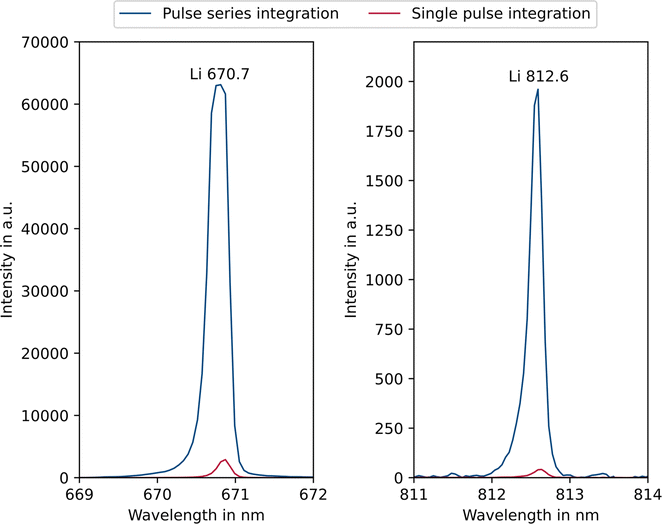 | ||
| Fig. 2 Influence of the integration setting on the intensity of selected lithium emission lines (1 mg L−1 Li) comparing measurement settings A (pulse series integration) and D (single pulse integration). | ||
One can see that applying the pulse series integration setting (blue) the main analytical line of lithium at 670.7 nm is saturated. In this case, however, it is possible to use the 812.6 nm emission line, as this is not saturated but still has a sufficiently high intensity. If single pulse integration (red) is applied, all intensities are reduced, and the main line can also be used. Depending on the sample composition and focus of the analysis this circumstance allows for an increased flexibility and dynamic range. In the application presented here, a long integration time is preferable because the impurities are present at low concentrations up to approx. 50 μg L−1. Consequently, the 812.6 nm emission line was mainly used for the lithium analysis. Alternatively, two separate parameter settings could be applied, one for the trace impurity elements and one for the lithium. However, this would be less time efficient and thus not preferable for on-site applications. The range of linear response is of particular importance in analytical chemistry. In classical ICP-OES, depending on emission line and matrix, linearity ranges of up to 6 orders of magnitude can be achieved60 and with SCGD 3–5 orders of magnitude.58 The typical linearity range of micro-discharge OES is illustrated in Fig. 3, using a lithium calibration from 0 to 10 mg L−1 as an example.
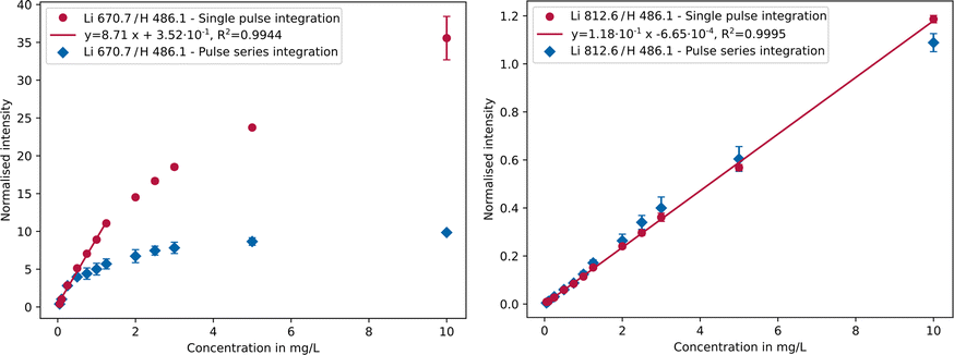 | ||
| Fig. 3 Calibration curves of the Li 670.7 nm (left) and Li 812.6 nm (right) emission lines comparing single pulse (red) and pulse series integration settings (blue). | ||
Due to saturation of the intense Li 670.7 nm line (Fig. 3, left) when using pulse series integration (blue), the response in this case is linear only up to 0.25 mg L−1 and the formation of a plateau is recognisable. Higher concentrations no longer follow a linear trend, instead deviating significantly from it limiting the linear range. By using single pulse integration (red), a linear response up to 1.25 mg L−1 was achieved. However, there is no recognisable plateau in the considered concentration range, as is the case with pulse series integration. Another contributing effect leading to non-linearity could be self-absorption, i.e. reabsorption of part of the radiation by the same emitting species, similar to the behaviour of laser induced breakdown spectroscopy analyses.61 By applying the single pulse integration setting on the Li 812.6 nm line (Fig. 3, right), it is possible to measure up to 10 mg L−1 with a linear response, yet the detection limit is higher compared to that of the Li 670.7 nm line as the weaker emission line is less sensitive. Consequently, a linearity range of up to about 3 orders of magnitude is achievable in both cases as can be seen in Table 2. The linearity range covers the range from the detection limit, which was determined using the blank value method,62 to the highest possible concentration at which a linear regression is still acceptable according to Mandel's test (α = 0.99).63
| Analytical parameter | Li 670.7 nm | Li 812.6 nm | Combineda | ||
|---|---|---|---|---|---|
| Single pulse | Pulse series | Single pulse | Pulse series | Single pulse | |
| a 0–1.25 mg L−1: Li 670.7 nm, 1.25–10 mg L−1: Li 812.6 nm. | |||||
| R 2 | 0.9944 | 0.9960 | 0.9995 | 0.9985 | — |
| LOD in μg L−1 | 3.51 | 6.59 | 43.2 | 10.8 | 3.51 |
| Upper limit in mg L−1 | 1.25 | 0.25 | 10 | 3 | 10 |
| Linearity range (orders) | 2.6 | 1.6 | 2.4 | 2.4 | 3.5 |
By combining both lines in single pulse mode, using lithium 670.7 nm from 0 to 1.25 mg L−1 and Li 812.6 nm from 1.25 to 10 mg L−1, the linear range can be extended to about 3.5 orders of magnitude. Depending on the concentration in the sample, either the more sensitive emission line (Li 670.7 nm, low concentrations) or the less sensitive one (Li 812.6 nm, high concentrations) can be used.
The differences between the two spectrometer settings can be explained by the fact that the detector saturates more quickly as the integration time increases (i.e. more pulses are integrated) and therefore reduces the upper linearity limit. It should be noted, however, that pulse series integration is required for less intense emission lines for accurate analysis. In particular, the two iron emission lines used (Fe 275.5 and 382.0 nm) require a longer integration time due to their low sensitivity. The iron emission lines at 238.2 nm and 259.9 nm, typically used in classical ICP-OES, are not feasible in this case due to interference of the tungsten electrode material used in this study.
Influence of the conductivity
One key parameter is the sample conductivity, which influences the properties of the plasma. With increasing sample conductivity, more free charge carriers are present in the solution, whereby especially the H+ concentration increases through addition of hydrochloric acid. The applied high voltage between the two electrodes can thus be better compensated, whereby the corona discharge becomes increasingly weaker and above a certain conductivity limit no discharge at all takes place. Experiments have shown that from approx. 15000 μS cm−1 onwards no discharge takes place.
As can be seen for the example of 500 μg L−1 lithium in Fig. 4, by comparing five different conductivity levels (1000/2500/5000/7500/10000 μS cm−1), the emission intensity decreases with increasing sample conductivity. Between 1000 μS cm−1 and 10000 μS cm−1 there is a factor of approx. 10.4 in the resulting signal intensity. Therefore, a conductivity of 1000 μS cm−1 should be used for the highest possible intensities. The advantage of a lower conductivity further lies in the fact that the conductivity adjustment is much faster and less acid is consumed. Lower conductivities were also tested, e.g., 500 μS cm−1. However, no further work was carried out after preliminary tests, because the concentration range available was limited as the conductivity of the samples themselves became too high above certain concentrations.
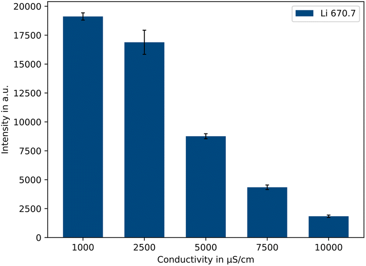 | ||
| Fig. 4 Influence of the conductivity on the intensity of the Li 670.7 nm emission line (500 μg L−1 Li, n = 5). | ||
Trace elements in Li2CO3
The concentrations of the trace elements were varied from 0 up to 44 μg L−1 (0/9/18/27/36/44 μg L−1) at different lithium concentration levels. In Fig. 5 the normalised intensities of selected sodium and potassium emission lines are plotted against the concentration.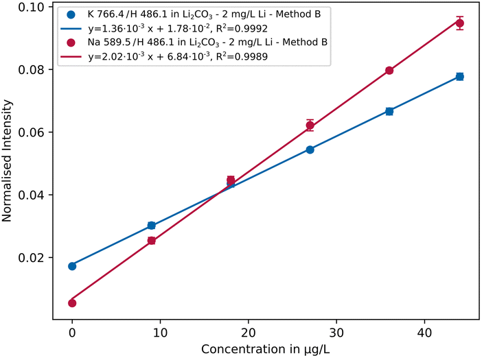 | ||
| Fig. 5 Calibration curves of the Na 589.5 nm and K 766.4 nm emission lines in lithium carbonate solution containing 2 mg L−1 Li using parameter setting B (n = 5). | ||
As can be seen, R2 > 0.999 and small repeatability error were achieved for both elements indicating low fluctuations of the analyte signals. In Table 3 the resulting sensitivities (slope of the calibration curve) are listed comparing different measurement settings with each other. It is apparent that setting A has lower sensitivity than B and C, with values differing by 1 order of magnitude in some cases. Overall parameter setting B yields the best results, whereby in some cases like for the emission lines K 766.4 nm or Na 589.5 nm the differences are rather small. A possible explanation is that a lower conductivity and lower plasma discharge energy result in a more stable plasma. An exception is aluminium, which is most sensitive with parameter setting C. Further investigations are necessary to explain the analytical behaviour in more detail.
| Emission line in nm | Sensitivity in a.u. μg L−1 | ||
|---|---|---|---|
| A | B | C | |
| a A: 2.0 J, 1000 μS cm; B: 1.2 J, 1000 μS cm; C: 2.0 J, 2500 μS cm; A–C: pulse series. | |||
| Al 394.4 | 8.54 × 10⁻⁵ | 1.24 × 10⁻⁴ | 1.89 × 10⁻⁴ |
| Al 396.1 | 1.99 × 10⁻⁴ | 2.88 × 10⁻⁴ | 4.21 × 10⁻⁴ |
| Fe 275.5 | 4.02 × 10⁻⁵ | 1.27 × 10⁻⁴ | 4.92 × 10⁻⁵ |
| Fe 382.0 | 2.46 × 10⁻⁵ | 7.49 × 10⁻⁵ | 2.67 × 10⁻⁵ |
| K 766.4 | 1.24 × 10⁻³ | 1.36 × 10⁻³ | 1.01 × 10⁻³ |
| K 769.8 | 6.25 × 10⁻⁴ | 6.72 × 10⁻⁴ | 5.07 × 10⁻⁴ |
| Na 588.9 | 3.95 × 10⁻³ | 4.09 × 10⁻³ | 3.16 × 10⁻³ |
| Na 589.5 | 1.95 × 10⁻³ | 2.02 × 10⁻³ | 1.56 × 10⁻³ |
| Zn 213.8 | 9.03 × 10⁻⁴ | 1.64 × 10⁻³ | 7.41 × 10⁻⁴ |
| Zn 481.0 | 1.91 × 10⁻⁴ | 3.21 × 10⁻⁴ | 1.20 × 10⁻⁴ |
The resulting detection and quantification limits obtained using parameter setting B are listed in Table 4. The figures of merit were calculated according to the calibration curve method.62 Limits of detection and quantification in the single-digit or lower μg L−1-range were achieved for almost all investigated elements, which is comparable to classical ICP-OES64 and SCGD analysis.65
| Emission line in nm | LOD in μg L−1 | LOQ in μg L−1 |
|---|---|---|
| Al 394.4 | 1.9 | 6.4 |
| Al 396.1 | 1.5 | 5.3 |
| Fe 275.5 | 3.8 | 11.7 |
| Fe 382.0 | 4.9 | 14.4 |
| K 766.4 | 1.0 | 3.5 |
| K 769.8 | 0.8 | 3.1 |
| Na 588.9 | 1.3 | 4.6 |
| Na 589.5 | 1.1 | 4.0 |
| Zn 213.8 | 1.2 | 4.4 |
| Zn 481.0 | 2.5 | 8.4 |
The data in Table 4 show that the trace elements investigated here can be measured well at low μg L−1-levels, whereby lithium-analyte-ratios of up to 2500:1 and 650:1 can be analysed according to the calculated limits of detection and limits of quantification, respectively. These concentration ratios are sufficient for the analysis of various intermediate products during lithium production. Nevertheless, higher concentration ratios are the aim of future work to allow the analysis of, for example, trace elements in battery grade and thermal nuclear grade Li2CO3, where purities of >99.5% and >99.9% are required, respectively.66
Influence of cross-element correlations
Especially for lighter elements such as Li, Na or K, cross correlations can occur, since they all belong to easily ionisable elements resulting in an excess of electrons that can shift the atom–ion equilibrium in the plasma towards atoms.67 This can lead to an under- or over-determination of the actual concentration in the sample, depending on the type of emission line. Alkali metals are usually overdetermined as the atomic lines are primarily used for analysis. Using the example of Na in lithium carbonate, the use of multi-linear models as a correction possibility was investigated. As can be seen in Fig. 6, the intensity of the Na signal (blue) increases with an increasing Li concentration (red), despite the concentration levels of the trace element remaining constant.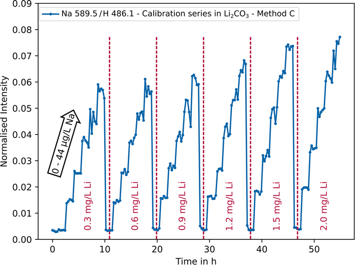 | ||
| Fig. 6 Normalised intensity of the Na 589.5 nm emission line as a function of sodium (0–44 μg L−1) and lithium concentrations (0.3–2.0 mg L−1) using parameter setting C. | ||
It can be deduced that cross correlation occurs, which needs to be considered for a more accurate quantitative analysis. Mathematically, this behaviour can be described by means of multi-linear models with interaction terms.68 For analysis, the data (180 measurement points) were randomly divided into training data (150/180 ≈ 80%) and testing data (30/180 ≈ 20%, n = 5 per concentration level). In practice, the concentration of the analyte is the target value and only the intensities can be measured. Therefore, the following model (eqn (1)) can be used.
| cAnalyte = k0 + k1IAnalyte + k2ILi + k3IAnalyteILi + k4IAnalyte2 + k5ILi2 | (1) |
Thereby, IAnalyte stands for the respective normalised intensity of a selected emission line of the analyte, ILi for the normalised intensity of the Li 812.6 nm line and ki for the corresponding constants. The term k3IAnalyteILi describes the mutual interaction that occurs. Using statistical packages in Python or Excel, the corresponding constants can be calculated based on the training data set and t-tests can be used to check whether the respective term is statistically significant. The evaluation resulted in the following mathematical relationship (eqn (2)) for the sodium concentration, which is valid for the concentration range under consideration.
| cNa =−1.15 + 829.37·INa589.5 − 24.48·ILi812.6 − 842.23·INa589.5·ILi812.6 + 73.64·ILi812.62 | (2) |
An adjusted coefficient of determination of Radj2 = 0.9878 was obtained for the model. In principle, the influence of other minor or trace elements can also be modelled. However, since overfitting should be avoided, only the influence of the main component Li was considered in this exemplary case. In Table 5 the recovery rates obtained by applying the model (eqn (2)) on the testing dataset are listed.
| c Na, target in μg L−1 | c Na, model in μg L−1 (n = 5) | RR in % (n = 5) |
|---|---|---|
| 9 | 9.22 ± 0.47 | 102.4 ± 5.2 |
| 18 | 18.36 ± 0.84 | 102.0 ± 4.6 |
| 27 | 27.59 ± 1.64 | 102.2 ± 6.1 |
| 35 | 35.49 ± 1.68 | 101.4 ± 4.8 |
| 44 | 44.81 ± 1.74 | 101.8 ± 4.0 |
As can be seen the model appropriately takes the cross correlation into account and there are only small deviations from the target value, which was experimentally given. Thus, with this approach the fully automated analysis of Na in lithium matrices with variable composition (within the model limits) is possible with good recovery rates in the range of approx. 96 to 108%, which is typically sufficient for fast on-site and on-line process monitoring.
Long-term stability measurement
To check the long-term stability of the analytical results, a LiOH solution with a lithium concentration of 1 mg L−1 was analysed 80 times in succession using parameter settings A and D, whereby a measurement was carried out every 7 minutes without additional rinsing in between. In Fig. 7, the intensity of the lithium 812.6 nm emission line normalised with hydrogen is plotted against the measurement time exemplary for parameter setting A. On the secondary y-axis the relative deviation in % around the mean value is shown.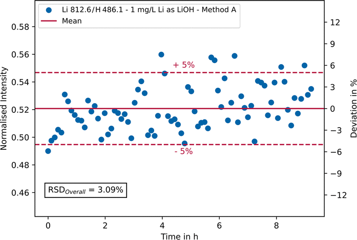 | ||
| Fig. 7 Long-term (>9 hours) stability measurement of a lithium hydroxide solution containing 1 mg L−1 Li using parameter setting A. The normalised intensity of the Li 812.6 nm emission line is plotted against time. The secondary y-axis shows the relative deviation in % around the mean value. | ||
As can be seen, most measurement points fall within a ± 5% range (red dashed lines) around the mean value (red line). This range represents a typical target value for industrial on-site measurements of saline process solutions. Furthermore, no trend can be seen, which allows the conclusion that no memory effects have occurred. In general, the repeatability is good, as can be seen from the overall RSD of approx. 3.1%. The addition of an internal standard, e.g., indium or yttrium, can further improve the results and has been tested during the experiments (not shown here). However, the addition of any chemicals should always be avoided in industrial on-site measurements. Using parameter setting D (single pulse integration) a RSD of 1.6% was achieved for the main analytical line of lithium at 670.7 nm, yet setting D cannot be used for simultaneous trace element analysis due to detection limits.
The repeatability measurement was also performed in the presence of 50 μg L−1 of the trace elements, whereby parameter settings A and B were compared. The results for the normalised intensities are given in Table 6. Here, the stability of the lithium signal is decreased by the presence of trace elements. However, for each element overall low relative standard deviations of less than 10% could be achieved by choosing the appropriate parameter setting out of the tested ones. For all investigated elements except aluminium (and Zn 481.0 nm) parameter setting A is slightly preferable. Consequently, these trace elements can also be analysed reliably over a longer period of time at μg L−1-levels.
| Emission line in nm | A | B |
|---|---|---|
| a A: 2.0 J, 1000 μS cm−1, pulse series; B: 1.2 J, 1000 μS cm−1, pulse series. | ||
| Al 394.4 | 7.72 | 3.98 |
| Al 396.1 | 6.76 | 4.27 |
| Fe 275.5 | 5.16 | 6.37 |
| Fe 382.0 | 6.96 | 7.27 |
| K 766.4 | 4.90 | 7.53 |
| K 769.8 | 5.00 | 7.69 |
| Li 812.6 | 9.89 | 13.33 |
| Na 588.9 | 6.60 | 10.91 |
| Na 589.5 | 7.24 | 11.67 |
| Zn 213.8 | 4.42 | 4.66 |
| Zn 481.0 | 6.68 | 4.70 |
Analysis of process samples
Reference measurements to verify the on-site micro-discharge OES results were carried out using laboratory ICP-OES. For the relevant elements of the selected process step (Li, Na, and K) there was a good agreement between both techniques with deviations of less than 10% for most samples (cf.Table 7), which can also be commonly observed between two different laboratories. In addition, it should be noted that on-site conditions are much less stable than laboratory conditions regarding temperature of the samples, vibrations or dust.| Sample | Li | Na | K | |||
|---|---|---|---|---|---|---|
| μDOES | ICP-OES | μDOES | ICP-OES | μDOES | ICP-OES | |
| a Laboratory ICP-OES: n = 5; on-site μDOES: n = 1 (continuous process). | ||||||
| 1 | 1.35 | 1.34 ± 0.14 | 4.53 | 4.53 ± 0.20 | 5.12 | 5.19 ± 0.34 |
| 2 | 1.29 | 1.30 ± 0.14 | 4.63 | 4.45 ± 0.21 | 5.22 | 5.50 ± 0.34 |
| 3 | 1.29 | 1.41 ± 0.15 | 4.04 | 4.56 ± 0.21 | 4.83 | 5.68 ± 0.35 |
| 4 | 1.26 | 1.16 ± 0.14 | 4.28 | 3.99 ± 0.20 | 5.27 | 5.02 ± 0.33 |
| 5 | 1.46 | 1.35 ± 0.14 | 4.64 | 4.35 ± 0.21 | 5.56 | 5.96 ± 0.35 |
Conclusions
Within the scope of this study, micro-discharge optical emission spectroscopy was investigated for its applicability for automated on-line analysis of impurities in lithium-containing salt solutions. The determination of Na, K, Al, Fe and Zn at a μg L−1-level in Li2CO3 and LiOH matrices and long-term stability of the measurements for verifying the repeatability was performed. Various parameters such as the plasma discharge energy, spectrometer integration setting and sample's electrical conductivity were optimised for the given sample systems. For the analysis of the trace elements in lithium carbonate and lithium hydroxide, precise and time–efficient parameter settings were developed. When analysing the trace elements Na, K, Al, Fe and Zn in lithium carbonate, it was found that a lower conductivity (1000 μS cm−1) and a lower plasma discharge energy (1.2 J) are beneficial. In most cases, high coefficients of determination (R2 > 0.99) as well as LODs and LOQs in the single-digit μg L−1-range were achieved, which is comparable to those of classical ICP-OES. Therefore, lithium-analyte ratios of up to 2500:1 can be measured. Improvements are still necessary to analyse higher matrix-analyte ratios. Currently high dilution ratios are required since conductivity is the limiting factor and must not exceed a certain value, as otherwise plasma stability will decrease. Furthermore, the linear range is currently limited compared to ICP-OES because measurements can be carried out over 3.5 orders of magnitude as shown for lithium. The use of modified electrodes or higher voltages and currents could be helpful to improve plasma stability at higher sample conductivities. An alternative approach would be to use the effect of the conductivity on plasma stability (lowering signal intensities) to enable the analysis of significantly higher concentrations. This would have the additional advantage that the samples would have to be diluted less, saving ultrapure water and time. Multi-linear regression models were successfully applied to correct for cross correlations that may occur with increasing matrix concentrations due to ionisation effects, as shown by the example of sodium in lithium carbonate where a Radj2 > 0.98 and recovery rates in the range of 96 to 108% were achieved. The disadvantage of this approach is that it has to be adapted to the specific sample type and matrix composition. However, this is not a problem when analysing industrial processes with a constant or rather steady sample composition where only small fluctuations occur. Furthermore, the procedure with Python (or other statistical programmes) is straightforward. Based on the long-term measurement of a sample with a concentration of 1 mg L−1 lithium (as LiOH) it was shown that a good repeatability can be achieved. With over 80 measurements in succession and a total measurement time of over 9 h, relative standard deviations of approx. 3% (Li 812.6 nm) and 1.6% (Li 670.7 nm) were obtained for the main component lithium using pulse series integration or single pulse integration, respectively. For trace elements in LiOH, low RSD% values (e.g. Zn or Al 4%) were obtained at a concentration of 50 μg L−1 in long-term measurements. On-site measurements were performed to monitor a selected process step of the lithium hydroxide production, whereby Li, Na and K were the most relevant elements. Laboratory ICP-OES measurements were carried out to verify the results and a good agreement between both techniques with deviations of less than 10% was found for most samples. In summary, it can be concluded that micro-discharge optical emission spectroscopy is promising for the considered challenge of automated on-line lithium process monitoring showing a good repeatability, long-term stability, linearity in the examined concentration ranges and detection limits in the single-digit μg L−1 range, and there is still potential for further improvements. The measurement method is also environmentally friendly, as no carrier gases such as argon or helium and no hazardous chemical reagents or organic solvents are required. The use of diluted hydrochloric acid (1%), to adjust the conductivity, is also minimal with only a few millilitres per analysis. The typical average power consumption is about 200 W (including PC for control and data analysis), which is much less than that required for classical ICP-OES (typically 1–2 kW)12 and in the range of that required by other micro-plasma techniques.58 A disadvantage, however, is the relatively high consumption of deionised water needed to dilute the originally concentrated solutions in the linear range. This can currently be as high as 25 Litres on one typical measurement day. Based on the “AGREE: Analytical GREennEss Calculator”,69 which takes 12 different categories such as energy consumption and degree of automation or sample preparation into account, a greenness score of 0.90 (maximum value is 1.0) was calculated. The aim of future work will include developments for increased matrix-analyte-ratios, expansion of the linear range and the investigation of other industry-relevant sample systems. Of particular interest would be the analysis of black mass, which is produced during the recycling of battery products and can contain other valuable metals such as Mn, Co or Ni in addition to Li and at much higher concentrations, but also graphite which could lead to unwanted interference. In collaboration with industrial partners, work is currently underway on the fully automated monitoring of the entire process chain directly at the industrial plant, from the calcined lithium-containing ore as the starting material to high-purity LiOH as the product, using ICP-OES and ion chromatography as reference methods.
Author contributions
Bastian Wiggershaus: conceptualization, data curation, formal analysis, investigation, methodology, software, validation, visualization, writing – original draft, Miisamari Jeskanen: data curation, investigation, supervision, validation, writing – review & editing, Aappo Roos: data curation, formal analysis, methodology, supervision, validation, writing – review & editing, Carla Vogt: conceptualization, funding acquisition, resources, supervision, writing – review & editing, and Toni Laurila: conceptualization, funding acquisition, resources, supervision, writing – review & editing.Conflicts of interest
There are no conflicts to declare.Acknowledgements
Parts of this work were funded by K-UTEC AG SALT TECHNOLOGIES. We acknowledge Ms. Johanna Helminen for her contribution to the analytical measurements.Notes and references
- National Research Council, Minerals, Critical Minerals, and the U. S. Economy, National Academies Press, Washington, D.C, 2008 Search PubMed.
- C. Dessemond, F. Lajoie-Leroux, G. Soucy, N. Laroche and J.-F. Magnan, Spodumene: The Lithium Market, Resources and Processes, Minerals, 2019, 9, 334 CrossRef CAS.
- J. Dewulf, G. van der Vorst, K. Denturck, H. van Langenhove, W. Ghyoot, J. Tytgat and K. Vandeputte, Recycling rechargeable lithium ion batteries: Critical analysis of natural resource savings, Resour., Conserv. Recycl., 2010, 54, 229–234 CrossRef.
- U.S. Department of the Interior, U.S. Geological Survey, Mineral Commodity Summaries 2022, 2022 Search PubMed.
- J. Xie and Y.-C. Lu, A retrospective on lithium-ion batteries, Nat. Commun., 2020, 11, 2499 CrossRef CAS.
- L. Talens Peiró, G. Villalba Méndez and R. U. Ayres, Lithium: Sources, Production, Uses, and Recovery Outlook, JOM, 2013, 65, 986–996 CrossRef.
- T. Tran and T. van Luong, in Lithium Process Chemistry, ed. A. Chagnes and J. Swiatowska, Elsevier Science, Burlington, 2015, pp. 81–124 Search PubMed.
- X. Yuan, J. Tang and Y. Duan, Microplasma Technology and Its Applications in Analytical Chemistry, Appl. Spectrosc. Rev., 2011, 46, 581–605 CrossRef.
- A. Müller, D. Pozebon and V. L. Dressler, Advances of nitrogen microwave plasma for optical emission spectrometry and applications in elemental analysis: a review, J. Anal. At. Spectrom., 2020, 35, 2113–2131 RSC.
- Z. Zhang and K. Wagatsuma, Matrix effects of easily ionizable elements and nitric acid in high-power microwave-induced nitrogen plasma atomic emission spectrometry, Spectrochim. Acta, Part B, 2002, 57, 1247–1257 CrossRef.
- K. H. Schoenbach and K. Becker, 20 years of microplasma research: a status report, Eur. Phys. J. D, 2016, 70 DOI:10.1140/epjd/e2015-60618-1.
- V. Karanassios, Microplasmas for chemical analysis: analytical tools or research toys?, Spectrochim. Acta, Part B, 2004, 59, 909–928 CrossRef.
- W. Li, Z. Yin, X. Cheng, W. Hang, J. Li and B. Huang, Pulsed microdischarge with inductively coupled plasma mass spectrometry for elemental analysis on solid metal samples, Anal. Chem., 2015, 87, 4871–4878 CrossRef CAS.
- M. Li, Y. Deng, C. Zheng, X. Jiang and X. Hou, Hydride generation-point discharge microplasma-optical emission spectrometry for the determination of trace As, Bi, Sb and Sn, J. Anal. At. Spectrom., 2016, 31, 2427–2433 RSC.
- C. Zheng, L. Hu, X. Hou, B. He and G. Jiang, Headspace Solid-Phase Microextraction Coupled to Miniaturized Microplasma Optical Emission Spectrometry for Detection of Mercury and Lead, Anal. Chem., 2018, 90, 3683–3691 CrossRef CAS PubMed.
- S. Zhang, H. Luo, M. Peng, Y. Tian, X. Hou, X. Jiang and C. Zheng, Determination of Hg, Fe, Ni, and Co by Miniaturized Optical Emission Spectrometry Integrated with Flow Injection Photochemical Vapor Generation and Point Discharge, Anal. Chem., 2015, 87, 10712–10718 CrossRef CAS PubMed.
- M. Li, K. Li, L. He, X. Zeng, X. Wu, X. Hou and X. Jiang, Point Discharge Microplasma Optical Emission Spectrometer: Hollow Electrode for Efficient Volatile Hydride/Mercury Sample Introduction and 3D-Printing for Compact Instrumentation, Anal. Chem., 2019, 91, 7001–7006 CrossRef CAS.
- K. H. Schoenbach, R. Verhappen, T. Tessnow, F. E. Peterkin and W. W. Byszewski, Microhollow cathode discharges, Appl. Phys. Lett., 1996, 68, 13–15 CrossRef CAS.
- K. H. Schoenbach, A. El-Habachi, W. Shi and M. Ciocca, High-pressure hollow cathode discharges, Plasma Sources Sci. Technol., 1997, 6, 468–477 CrossRef CAS.
- R. M. Sankaran and K. P. Giapis, Hollow cathode sustained plasma microjets: Characterization and application to diamond deposition, J. Appl. Phys., 2002, 92, 2406–2411 CrossRef CAS.
- S.-A. Xia, A. Leng, Y. Lin, L. Wu, Y. Tian, X. Hou and C. Zheng, Integration of Flow Injection Capillary Liquid Electrode Discharge Optical Emission Spectrometry and Microplasma-Induced Vapor Generation: A System for Detection of Ultratrace Hg and Cd in a Single Drop of Human Whole Blood, Anal. Chem., 2019, 91, 2701–2709 CrossRef CAS PubMed.
- J. Tang, Y. Duan and W. Zhao, Characterization and mechanism studies of dielectric barrier discharges generated at atmospheric pressure, Appl. Phys. Lett., 2010, 96, 191503 CrossRef.
- S. Liu, X.-X. Xue, Y.-L. Yu and J.-H. Wang, “Insert-and-Go” Activated Carbon Electrode Tip for Heavy Metal Capture and In Situ Analysis by Microplasma Optical Emission Spectrometry, Anal. Chem., 2021, 93, 6262–6269 CrossRef CAS PubMed.
- D. C. Liang and M. W. Blades, Atmospheric pressure capacitively coupled plasma atomizer for atomic absorption spectrometry, Anal. Chem., 1988, 60, 27–31 CrossRef CAS.
- T. Frentiu, S. Butaciu, M. Ponta, E. Darvasi, M. Senila, D. Petreus and M. Frentiu, Simultaneous determination of As and Sb in soil using hydride generation capacitively coupled plasma microtorch optical emission spectrometry – comparison with inductively coupled plasma optical emission spectrometry, J. Anal. At. Spectrom., 2014, 29, 1880–1888 RSC.
- J. Hopwood, O. Minayeva and Y. Yin, Fabrication and characterization of a micromachined 5 mm inductively coupled plasma generator, J. Vac. Sci. Technol. B, 2000, 18, 2446 CrossRef CAS.
- J. A. Hopwood, A microfabricated inductively coupled plasma generator, J. Microelectromech. Syst., 2000, 9, 309–313 CAS.
- F. Iza and J. Hopwood, Influence of operating frequency and coupling coefficient on the efficiency of microfabricated inductively coupled plasma sources, Plasma Sources Sci. Technol., 2002, 11, 229–235 CrossRef.
- O. B. Minayeva and J. A. Hopwood, Emission spectroscopy using a microfabricated inductively coupled plasma-on-a-chip : Invited Lecture, J. Anal. At. Spectrom., 2002, 17, 1103–1107 RSC.
- Y. Yin, J. Messier and J. A. Hopwood, Miniaturization of inductively coupled plasma sources, IEEE Trans. Plasma Sci., 1999, 27, 1516–1524 CrossRef.
- T. Ichiki, T. Koidesawa and Y. Horiike, An atmospheric-pressure microplasma jet source for the optical emission spectroscopic analysis of liquid sample, Plasma Sources Sci. Technol., 2003, 12, S16–S20 CrossRef CAS.
- Y. Duan, Y. Su, Z. Jin and S. P. Abeln, A field-portable plasma source monitor for real-time air particulate monitoring, Anal. Chem., 2000, 72, 1672–1679 CrossRef CAS PubMed.
- Y. Duan, Y. Su, Z. Jin and S. P. Abeln, Design and development of a highly sensitive, field portable plasma source instrument for on-line liquid stream monitoring and real-time sample analysis, Rev. Sci. Instrum., 2000, 71, 1557–1563 CrossRef CAS.
- X. Pan, Y. Lin, Y. Su, J. Yang, L. He, Y. Deng, X. Hou and C. Zheng, Methanol-Enhanced Liquid Electrode Discharge Microplasma-Induced Vapor Generation of Hg, Cd, and Zn: The Possible Mechanism and Its Application, Anal. Chem., 2021, 93, 8257–8264 CrossRef CAS.
- K. Greda, M. Welna, A. Szymczycha-Madeja and P. Pohl, Sensitive determination of Ag, Bi, Cd, Hg, Pb, Tl, and Zn by inductively coupled plasma optical emission spectrometry combined with the microplasma-assisted vapor generation, Talanta, 2022, 249, 123694 CrossRef CAS.
- Y. Cai, Y.-L. Yu and J.-H. Wang, Alternating-Current-Driven Microplasma for Multielement Excitation and Determination by Optical-Emission Spectrometry, Anal. Chem., 2018, 90, 10607–10613 CrossRef CAS PubMed.
- V. Stelmashuk, V. Prukner, K. Kolacek, A. Tuholukov, P. Hoffer, J. Straus, O. Frolov and V. Jirasek, Optical Emission Spectroscopy of Underwater Spark Generated by Pulse High-Voltage Discharge with Gas Bubble Assistant, Processes, 2022, 10, 1474 CrossRef CAS.
- P. Bruggeman, T. Verreycken, M. Á. González, J. L. Walsh, M. G. Kong, C. Leys and D. C. Schram, Optical emission spectroscopy as a diagnostic for plasmas in liquids: opportunities and pitfalls, J. Phys. D: Appl. Phys., 2010, 43, 124005 CrossRef.
- T. Shirafuji, Y. Ogura and Y. Himeno, Time-resolved optical emission spectroscopy on three-dimensionally integrated micro-solution plasma, Jpn. J. Appl. Phys., 2014, 53, 10211 CrossRef CAS.
- P. J. Bruggeman, M. J. Kushner, B. R. Locke, J. G. E. Gardeniers, W. G. Graham, D. B. Graves, R. C. H. M. Hofman-Caris, D. Maric, J. P. Reid, E. Ceriani, D. Fernandez Rivas, J. E. Foster, S. C. Garrick, Y. Gorbanev, S. Hamaguchi, F. Iza, H. Jablonowski, E. Klimova, J. Kolb, F. Krcma, P. Lukes, Z. Machala, I. Marinov, D. Mariotti, S. Mededovic Thagard, D. Minakata, E. C. Neyts, J. Pawlat, Z. L. Petrovic, R. Pflieger, S. Reuter, D. C. Schram, S. Schröter, M. Shiraiwa, B. Tarabová, P. A. Tsai, J. R. R. Verlet, T. von Woedtke, K. R. Wilson, K. Yasui and G. Zvereva, Plasma–liquid interactions: a review and roadmap, Plasma Sources Sci. Technol., 2016, 25, 53002 CrossRef.
- S. M. Korobeinikov, A. V. Melekhov and A. S. Besov, High Temp., 2002, 40, 652–659 CrossRef CAS.
- J. Wu, J. Yu, J. Li, J. Wang and Y. Ying, Detection of metal ions by atomic emission spectroscopy from liquid-electrode discharge plasma, Spectrochim. Acta, Part B, 2007, 62, 1269–1272 CrossRef.
- K.-Y. Shih and B. R. Locke, Optical and Electrical Diagnostics of the Effects of Conductivity on Liquid Phase Electrical Discharge, IEEE Trans. Plasma Sci., 2011, 39, 883–892 CAS.
- S. M. Thagard, K. Takashima and A. Mizuno, Chemistry of the Positive and Negative Electrical Discharges Formed in Liquid Water and Above a Gas–Liquid Surface, Plasma Chem. Plasma Process., 2009, 29, 455–473 CrossRef CAS.
- B. Pongrac, M. Simek, M. Clupek, V. Babicky and P. Lukes, in 2017 IEEE 19th International Conference on Dielectric Liquids (ICDL), IEEE, Piscataway, NJ, 2017, pp. 1–3 Search PubMed.
- B. Pongrác, M. Šimek, M. Člupek, V. Babický and P. Lukeš, Spectroscopic characteristics of H α/O I atomic lines generated by nanosecond pulsed corona-like discharge in deionized water, J. Phys. D: Appl. Phys., 2018, 51, 124001 CrossRef.
- Y. Yang, Y. I. Cho and A. A. Fridman, Plasma discharge in liquid. Water Treatment and Applications, CRC Press, Boca Raton, FL, 2012 Search PubMed.
- D. Dobrynin, Y. Seepersad, M. Pekker, M. Shneider, G. Friedman and A. Fridman, Non-equilibrium nanosecond-pulsed plasma generation in the liquid phase (water, PDMS) without bubbles: fast imaging, spectroscopy and leader-type model, J. Phys. D: Appl. Phys., 2013, 46, 105201 CrossRef.
- B. Sun, M. Sato and J. Sid Clements, Optical study of active species produced by a pulsed streamer corona discharge in water, J. Electrost., 1997, 39, 189–202 CrossRef CAS.
- B. Sun, M. Sato, A. Harano and J. Clements, Non-uniform pulse discharge-induced radical production in distilled water, J. Electrost., 1998, 43, 115–126 CrossRef CAS.
- P. Sunka, V. Babický, M. Clupek, P. Lukes, M. Simek, J. Schmidt and M. Cernák, Generation of chemically active species by electrical discharges in water, Plasma Sources Sci. Technol., 1999, 8, 258–265 CrossRef CAS.
- C. Jia, T. Zhang, S. Y. Maksimov and X. Yuan, Spectroscopic analysis of the arc plasma of underwater wet flux-cored arc welding, J. Mater. Process. Technol., 2013, 213, 1370–1377 CrossRef CAS.
- Q. He, Z. Zhu and S. Hu, Flowing and Nonflowing Liquid Electrode Discharge Microplasma for Metal Ion Detection by Optical Emission Spectrometry, Appl. Spectrosc. Rev., 2014, 49, 249–269 CrossRef CAS.
- P. Zheng, Y. Yang, J. Wang, H. I. A. Qazi, M. Wu, Y. He, Q. Hu and N. Ding, Development of milli-second pulsed atmospheric pressure solution cathode glow discharge optical emission spectroscopy for detecting metal elements in aqueous solution, J. Anal. At. Spectrom., 2022, 37, 1806–1814 RSC.
- M. R. Webb, F. J. Andrade, G. Gamez, R. McCrindle and G. M. Hieftje, Spectroscopic and electrical studies of a solution-cathode glow discharge, J. Anal. At. Spectrom., 2005, 20, 1218 RSC.
- K. Blomberg von der Geest, M. Jeskanen, A. Mäkinen and M. Sarén, Optical Measurement Apparatus and Method, WO/2021/058853A1, 2021.
- P. Leukkunen, K. Blomberg von der Geest and A. Mäkinen, Apparatus for generating ionization, optical measurement apparatus and measurement method, WO/2017/103341A2, 2017.
- N. Hazel, J. Orejas Ibanez and S. Ray, A novel solution cathode glow discharge geometry for improved coupling to optical emission spectrometry, J. Anal. At. Spectrom., 2022, 37, 1229–1239 RSC.
- Z.-M. Zhang, S. Chen and Y.-Z. Liang, Baseline correction using adaptive iteratively reweighted penalized least squares, Analyst, 2010, 135, 1138–1146 RSC.
- J. W. Olesik, Elemental analysis using ICP-OES and ICP/MS, Anal. Chem., 1991, 63, 12A–21A CrossRef CAS.
- F. Rezaei, G. Cristoforetti, E. Tognoni, S. Legnaioli, V. Palleschi and A. Safi, A review of the current analytical approaches for evaluating, compensating and exploiting self-absorption in Laser Induced Breakdown Spectroscopy, Spectrochim. Acta, Part B, 2020, 169, 105878 CrossRef CAS.
- Deutsches Institut für Normung e.V., Chemical analysis - Decision limit, detection limit and determination limit under repeatability conditions - Terms, methods, evaluation, Beuth Verlag GmbH, DIN 32645:2008-11, Berlin, 2008 Search PubMed.
- L. Brüggemann, W. Quapp and R. Wennrich, Test for non-linearity concerning linear calibrated chemical measurements, Accredit. Qual. Assur., 2006, 11, 625–631 CrossRef.
- B. M. Fontoura, F. C. Jofré, T. Williams, M. Savio, G. L. Donati and J. A. Nóbrega, Is MIP-OES a suitable alternative to ICP-OES for trace element analysis?, J. Anal. At. Spectrom., 2022, 37, 966–984 RSC.
- P. Pohl, P. Jamroz, K. Swiderski, A. Dzimitrowicz and A. Lesniewicz, Critical evaluation of recent achievements in low power glow discharge generated at atmospheric pressure between a flowing liquid cathode and a metallic anode for element analysis by optical emission spectrometry, TrAC, Trends Anal. Chem., 2017, 88, 119–133 CrossRef CAS.
- N. Linneen, R. Bhave and D. Woerner, Purification of industrial grade lithium chloride for the recovery of high purity battery grade lithium carbonate, Sep. Purif. Technol., 2019, 214, 168–173 CrossRef CAS.
- P. J. Galley, M. Glick and G. M. Hieftje, Easily ionizable element interferences in inductively coupled plasma atomic emission spectroscopy—I, Spectrochim. Acta, Part B, 1993, 48, 769–788 CrossRef.
- N. H. Bingham, Regression. Linear Models in Statistics, Springer London, London, 2010 Search PubMed.
- F. Pena-Pereira, W. Wojnowski and M. Tobiszewski, AGREE-Analytical GREEnness Metric Approach and Software, Anal. Chem., 2020, 92, 10076–10082 CrossRef CAS PubMed.
Footnote |
| † Electronic supplementary information (ESI) available. See DOI: https://doi.org/10.1039/d4ja00044g |
| This journal is © The Royal Society of Chemistry 2024 |