Side chain isomerization enables high efficiency and thickness tolerant organic solar cells†
Zhixiang
Li‡
a,
Bailin
Zhou‡
a,
Shuchao
Zhang‡
a,
Changzun
Jiang
a,
Yalu
Zou
a,
Shitong
Li
a,
Yang
Yang
b,
Zhaoyang
Yao
 a,
Xiangjian
Wan
 *a and
Yongsheng
Chen
 *a
*a
aState Key Laboratory of Elemento-Organic Chemistry, The Centre of Nanoscale Science and Technology and Key Laboratory of Functional Polymer Materials, College of Chemistry, Haihe Laboratory of Sustainable Chemical Transformations, Renewable Energy Conversion and Storage Center (RECAST), Nankai University, Tianjin 300071, China. E-mail: xjwan@nankai.edu.cn; yschen99@nankai.edu.cn
bThe Institute of Seawater Desalination and Multipurpose Utilization, Ministry of Natural Resources (Tianjin), Tianjin 300192, China
First published on 2nd December 2022
Abstract
Side chain engineering is an efficient strategy for modifying molecular properties and regulating active layer morphologies, thus improving the performance of organic solar cells (OSCs). Here, we design two acceptors, namely FEH2C8-2Cl and F3EH-2Cl, based on an acceptor F-2Cl by introducing isomerized side chains on the molecular backbones. Film absorptions, energy levels and packing behaviors of the three isomer acceptors show a considerable difference with the isomer side chains. Using PM6 as a donor, the FEH2C8-2Cl-based device affords the best power conversion efficiency (PCE) of 14.60% with a high fill factor of 79.04% owing to the more favorable active layer morphology. Moreover, the device based on FEH2C8-2Cl shows good active layer thickness tolerance with an efficiency of 12.14% at a thickness of 300 nm, which is favored for the fabrication of large area OSCs. Finally, a large area module fabricated with PM6:FEH2C8-2Cl as the active layer shows a PCE of 11.71% with an area of 25 cm2.
1. Introduction
As one of the promising photovoltaic technologies for addressing energy and environmental issues, organic solar cells (OSCs) have the characteristics of low cost, flexibility, lightweightness, environmental friendliness, large-area printing manufacture, etc.1–5 To date, the power conversion efficiency (PCE) of OSCs has reached remarkable values exceeding 19% owing to the invention of new active layer materials, especially non-fullerene acceptors (NFAs) with acceptor–donor–acceptor (A–D–A) architectures6–13 and efficient morphology control14–18 for device fabrication and optimization. In the past decade, side chain engineering has proven to be an efficient method for the delicate design of active layer materials and precise regulation of the corresponding morphology because solubility,19,20 crystallization21 and packing modes,22,23etc. are substantially affected by the side chains of the active layer materials.24 Consequently, there has been much interest in introducing isomer side chains for the careful tuning of molecular properties and resulting active layer morphologies. For instance, Sun et al. designed an acceptor L8-BO by replacing the linear chains on the beta position of Y6 with isomer-branched alkyl chains. It was found that this slight chemical structure modification significantly influenced the molecular packing mode and led to the enhanced structural order and improved the charge transport in solid thin films. Finally, an excellent efficiency of 18.32% was obtained.22However, state-of-the-art OSCs with high efficiencies are typically fabricated with an optimal active layer thickness of around 100 nm, while further increasing the thickness of the active layer leads to substantially decreasing PCEs. However, a thickness of around 100 nm for active layers is unsuitable for the large area production of OSCs because it is difficult to produce uniform and defect-free films upon industrial high throughput manufacturing. Consequently, employing thicker active layers over several hundred nano-meters is essential for meeting the requirement for large-scale fabrication.25,26 The exciton diffusion length, charge-carrier mobilities, and charge recombination are the main factors that influence the PCE of thick-film OSCs owing to more D–A interfaces in the thick film active layers.27,28 In addition, a proper vertical phase distribution can facilitate charge transport, which is beneficial for thick-film OSCs. To this end, it is necessary to develop new donor and acceptor materials with high mobility and thickness tolerance.29–31 In the past decade, many efforts have been made to design materials for thick film OSCs. Careful modification of molecules by side-chains with different lengths, dimensions, and substituted positions has proved to be an efficient method for fine tuning the designed molecular properties for thick film tolerance devices. For example, Bao and co-workers reported three acceptors IDIC-CXPh (X = 4, 5 or 6) with different length side chains. The IDIC-C5Ph-based device maintained a 13.01% PCE under the active layer thickness of ∼500 nm, which is much higher than the other two acceptor-based devices.32
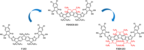
Our group has previously reported an excellent acceptor F-2Cl that showed both high efficiency and good film thickness tolerance.33,34 Herein, considering the remarkable effects of side chains on the molecule properties and device performance, we design and synthesize two acceptors FEH2C8-2Cl and F3EH-2Cl by replacing the linear n-octyl side chains on the backbone of F-2Cl with the branched 2-ethylhexyl side chains (Fig. 1). The results show that the change in the alkyl side chains significantly affects the three acceptor solid film absorptions, indicating that the molecular packings change with the isomer side chains. Importantly, the active layer morphologies of the three acceptor blend films with PM6 can also be finely tuned via the isomer side chains. With a more suitable active layer morphology, the OSC based on FEH2C8-2Cl delivered a PCE of 14.60% with a Voc of 0.918 V, a Jsc of 20.12 mA cm−2 and an excellent FF of 79.04%, which is better than those of the devices based on F-2Cl (14.07%) and F3EH-2Cl (13.79%). The FF of 79.04% is one of the highest FFs other than OSCs based on Y6 derivatives.35–37 Moreover, the device based on FEH2C8-2Cl demonstrates good active layer thickness tolerance with an efficiency of 12.14% at a thickness of 300 nm. Finally, a module is fabricated with PM6:FEH2C8-2Cl as the active layer and showed a PCE of 11.71% with a large area of 25 cm2.
2. Results and discussion
2.1 Synthesis and characterization
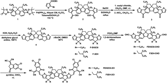
The synthesis routes of the target acceptors FEH2C8-2Cl and F3EH-2Cl are illustrated in Scheme 1 following a similar synthesis method of F-2Cl.38 First, intermediate compound 2 was synthesized from ethyl 2-bromothiophene-3-carboxylate and 2,7-bis(4,4,5,5-tetramethyl-1,3,2-dioxaborolan-2-yl)-9,9-bis(2-ethylhexyl) fluorene (compound 1) via the Suzuki coupling. Then, 2 was hydrolyzed and the crude product was directly used in the next Friedel–Crafts reaction under the catalysis of AlCl3 to afford 3. Next, compound 4 was obtained by a reduction of 3. Subsequently, the intermediates F-EH2C8 and F-3EH were synthesized by the alkylation of 4 with 1-bromooctane and 2-ethylhexyl bromide, respectively. Then, the dialdehyde compounds FEH2C8-2CHO and F3EH-2CHO were produced through the Vilsmeier–Haack reaction. Finally, the target acceptors FEH2C8-2Cl and F3EH-2Cl were afforded via condensation reaction between the above dialdehydes and 2-(5,6-dichloro-3-oxo-2,3-dihydro-1H-inden-1-ylidene) malononitrile. The detailed synthesis procedure and characterizations including 1H NMR, 13C NMR and mass spectra are provided in the ESI.†2.2 Optical and electrochemical properties
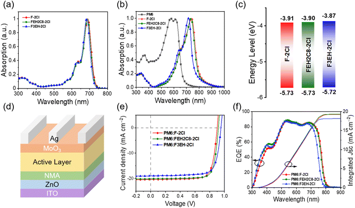
The UV-vis absorption spectra of F-2Cl, FEH2C8-2Cl, and F3EH-2Cl in the solution and solid films are shown in Fig. 3a and b. The three acceptors exhibited similar absorption behaviours in their chloroform solutions. However, in solid films, the absorption spectra of F-2Cl, FEH2C8-2Cl and F3EH-2Cl significantly red shift with the maximum absorption peaks (λmax) of 740, 735, and 716 nm, respectively, owing to the strong intermolecular interactions. Clearly, as more branched chains are introduced, the absorptions of the neat films of the three acceptor blue shift gradually owing to the increasing hindrance from the branched chains, thus decreasing the interactions of molecules. The film absorption onsets of F-2Cl, FEH2C8-2Cl, and F3EH-2Cl are 800, 793, and 758 nm, respectively, corresponding to the optical bandgaps of 1.55, 1.56, and 1.64 eV. Cyclic Voltammetry (CV) measurements were carried out to investigate the electrochemical properties of the three acceptors (Fig. S2†), and the corresponding energy level diagram is shown in Fig. 3c. The LUMOs/HOMOs of F-2Cl, FEH2C8-2Cl, and F3EH-2Cl were determined to be −3.91/−5.73, −3.90/−5.73, and −3.87/−5.72 eV, respectively. The electrochemical gaps of the three acceptors are 1.82, 1.83, and 1.85 eV, respectively, which show a similar trend but large values compared with the corresponding optical bandgap values. This mainly comes from the different definitions and measurement conditions of the two measurement methods.39 The detailed data of the absorption and energy levels of F-2Cl, FEH2C8-2Cl, and F3EH-2Cl are listed in Table 1.| NFAs | λ CFmax (nm) | λ filmmax (nm) | λ filmonset (nm) | E optg (eV) | HOMO (eV) | LUMO (eV) | E cvg (eV) |
|---|---|---|---|---|---|---|---|
| F-2Cl | 689 | 740 | 800 | 1.55 | −5.73 | −3.91 | 1.82 |
| FEH2C8-2Cl | 687 | 735 | 793 | 1.56 | −5.73 | −3.90 | 1.83 |
| F3EH-2Cl | 683 | 716 | 758 | 1.64 | −5.72 | −3.87 | 1.85 |
2.3 Photovoltaic performance
To evaluate the photovoltaic properties of the three acceptors, inverted devices with the structure of ITO/ZnO/NMA/Active layer/MoO3/Ag (Fig. 2d) were fabricated and optimized, where PM6 was employed as the donor owing to its matched energy level and complementary absorption with the three acceptors, and NMA is 2-(3-(dimethylamino)propyl)-1,3-dioxo-2,3-dihydro-1H-benzo[de]isoquinoline-6,7-dicarboxylic acid, which is an efficient interface layer we recently reported.40 It can reduce the content of defect oxygen on the surface of ZnO film, suppress the photo-catalysis capacity of ZnO and improve the corresponding device performance. The detailed device data are listed in Tables S1–S8,† and the photovoltaic parameters of the best OSCs are shown in Fig. 2e, 3f and Table 2. Among the OSCs based on the three acceptors, FEH2C8-2Cl-based devices afford the best PCE of 14.60%, with open-circuit voltage (Voc) of 0.918 V, short current density (Jsc) of 20.12 mA cm−2 and outstanding fill factor (FF) of 79.04%. Compared with those that reported high efficiency binary devices with PM6 as the donor (Table S11†), the FEH2C8-2Cl device shows compatible and impressive Voc and FF. Its PCE is limited by the moderate Jsc owing to the relatively narrow absorption range of FEH2C8-2Cl. In comparison, F-2Cl- and FEH2C8-2Cl-based devices afforded relatively low PCEs with values of 14.07% and 13.79%, respectively. The excellent FF of FEH2C8-2Cl-based OSC is mainly due to the higher and more balanced carrier mobilities, as well as the more suitable morphology, as discussed below. As the linear chains in the molecules are gradually replaced by the branched chains, the Voc of the device increases gradually owing to the up-shifted LUMOs of the corresponding acceptors. As shown in Fig. 2f, the OSCs of the three acceptors show a high EQE response with a maximum EQE value of over 85% at around 540 nm. Note that F-2Cl- and FEH2C8-2Cl-based devices exhibit wider EQE response ranges than those based on F3EH-2Cl, which agrees with their absorption ranges. The integrated current densities from the EQE measurements agree well with the values from the J–V measurements (Table 2).| Devices | V oc (V) | J sc (mA cm−2) | J EQEsc (mA cm−2) | FFa (%) | PCEa (%) |
|---|---|---|---|---|---|
| a The average parameters included in the brackets were calculated from more than 10 devices. | |||||
| PM6:F-2Cl | 0.901 (0.897 ± 0.003) | 20.14 (20.07 ± 0.17) | 19.53 | 77.54 (77.30 ± 0.36) | 14.07 (13.94 ± 0.13) |
| PM6:FEH2C8-2Cl | 0.918 (0.914 ± 0.003) | 20.12 (19.89 ± 0.19) | 19.56 | 79.04 (79.00 ± 0.29) | 14.60 (14.39 ± 0.15) |
| PM6:F3EH-2Cl | 0.952 (0.953 ± 0.004) | 18.99 (18.78 ± 0.23) | 18.31 | 76.25 (75.77 ± 0.61) | 13.79 (13.55 ± 0.16) |
2.4 Charge transport, exciton dissociation and charge generation
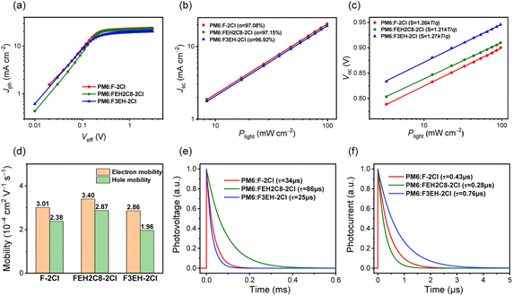
As shown in Fig. 3a, photocurrent densities (Jph) versus effective voltages (Veff) for the optimized devices were measured. All the OSCs' current densities reached saturation under high Veff, displaying negligible carrier recombination. The exciton dissociation efficiency (Pdiss) and carrier collection efficiency (Pcoll) are 96.22%/87.01%, 96.37%/87.27% and 95.94%/82.42% for F-2Cl-, FEH2C8-2Cl- and F3EH-2Cl-based OSCs, respectively. Better Pdiss and Pcoll for FEH2C8-2Cl-based devices are beneficial for their photovoltaic performance. We also measured the Jsc and Voc characteristics versus light densities (P) of F-2Cl-, FEH2C8-2Cl- and F3EH-2Cl-based OSCs to evaluate the carrier recombination. The relationship between Jsc and P can be described with Jsc ∝ Pα. The closer the value of α is to 1, the less bimolecular recombination occurs in the devices. The α of F-2Cl-, FEH2C8-2Cl-, and F3EH-2Cl-based OSCs are 97.08%, 97.15%, and 96.92%, respectively (Fig. 3b). Moreover, Voc and P follow Voc ∝ S![[thin space (1/6-em)]](https://www.rsc.org/images/entities/char_2009.gif) ln
ln![[thin space (1/6-em)]](https://www.rsc.org/images/entities/char_2009.gif) P. When the S value is approximately kT/q, the trap-free carrier transport can be achieved. The values of S for F-2Cl-, FEH2C8-2Cl-, and F3EH-2Cl-based OSCs are 1.26kT/q, 1.21kT/q, and 1.27kT/q, respectively (Fig. 3c). The results suggest that the FEH2C8-2Cl-based device has less recombination, which agrees with the higher FF and EQE responses.
P. When the S value is approximately kT/q, the trap-free carrier transport can be achieved. The values of S for F-2Cl-, FEH2C8-2Cl-, and F3EH-2Cl-based OSCs are 1.26kT/q, 1.21kT/q, and 1.27kT/q, respectively (Fig. 3c). The results suggest that the FEH2C8-2Cl-based device has less recombination, which agrees with the higher FF and EQE responses.
To further explore the improved FF of FEH2C8-2Cl-based OSCs, charge mobilities were measured using the space-charge-limited current (SCLC) method. As shown in Fig. 3d, the electron (μe) and hole mobilities (μh) of F-2Cl-, FEH2C8-2Cl- and F3EH-2Cl-based devices are 3.01 × 10⁻⁴/2.38 × 10−4, 3.40 × 10⁻⁴/2.87 × 10−4 and 2.86 × 10⁻⁴/1.96 × 10−4 cm2 V−1 s−1, respectively. FEH2C8-2Cl-based devices possess the highest carrier mobilities, and a more balanced ratio of μe/μh (1.18) compared to those of F-2Cl (1.26)- and F3EH-2Cl (1.46)-based devices, which agrees well with its better FF. Transient photovoltage (TPV) and transient photocurrent (TPC) measurements were implemented to further quantify the carrier recombination and transport processes. As depicted in Fig. 3e, the charge-carrier lifetime τ are 34, 86, and 25 μs for F-2Cl-, FEH2C8-2Cl-, and F3EH-2Cl-based devices, respectively. The prolonged lifetime of FEH2C8-2Cl-based OSC indicates less carrier recombination compared with those of F-2Cl and F3EH-2Cl-based OSCs. Moreover, FEH2C8-2Cl-based OSC also exhibits a faster carrier-extraction process (0.28 μs) with respect to those of F-2Cl-based OSC (0.43 μs) and F3EH-2Cl-based OSC (0.76 μs). The above results demonstrate more efficient carrier transport and collection in FEH2C8-2Cl-based OSCs (Fig. 3f).
2.5 Morphology analysis
We used atomic force microscopy (AFM) and transmission electron microscopy (TEM) to investigate the morphologies of F-2Cl-, FEH2C8-2Cl- and F3EH-2Cl-based OSCs. As demonstrated in Fig. S5,† the blend films of PM6:F-2Cl, PM6:FEH2C8-2Cl and PM6:F3EH-2Cl have small root-mean-square roughness values of 1.60, 1.54, and 1.67 nm, respectively. For the TEM images shown in Fig. S5,† the cross interpenetrating network morphology can be observed for all three blends. Grazing-incidence wide-angle X-ray scattering (GIWAXS) is also measured in both neat and blended films with PM6 for the three acceptors (Fig. 4, S6 and Table S10†). As shown in Fig. S6,† clear (010) and (100) diffraction peaks can be observed in the out-of-plane (OOP) and in-plane (IP) directions of the three neat films, indicating that face-on orientation is dominant. The π–π stacking distances in the neat films of F-2Cl, FEH2C8-2Cl and F3EH-2Cl are 3.44, 3.43, and 3.63 Å, respectively. The nearly identical values of π–π stacking distances indicate that the side chain isomerization only on the central fluorene has little effect on the molecular packing behaviour, which also agrees with their similar solid film absorptions. In contrast, F3EH-2Cl shows larger π–π stacking distances than the other two molecules owing to the bulk hindrance of the isomer side chains on all the sp3 carbon in the molecular backbone. When blended with PM6, the face-on orientation of films (Fig. 4d–f) remains, and the corresponding stacking distances are similar to those of the neat film, which are 3.54, 3.51, and 3.56 Å. The crystal coherence length (CCL) corresponding to the (010) diffraction peaks for the F-2Cl, FEH2C8-2Cl, and F3EH-2Cl-based blend films are 27.79 Å, 28.06 Å, and 20.45 Å, respectively. The slightly intense π–π stacking and large CCL of the FEH2C8-2Cl blend film are conducive to more effective carrier transportation and improved device performance.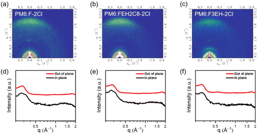 | ||
| Fig. 4 2D-GIWAXS of (a) PM6:F-2Cl; (b) PM6:FEH2C8-2Cl; (c) PM6:F3EH-2Cl blends and the corresponding line-cut profiles of (d) PM6:F-2Cl; (e) PM6:FEH2C8-2Cl; and (f) PM6:F3EH-2Cl blend films. | ||
2.6 Thick-film OSCs and large area modules
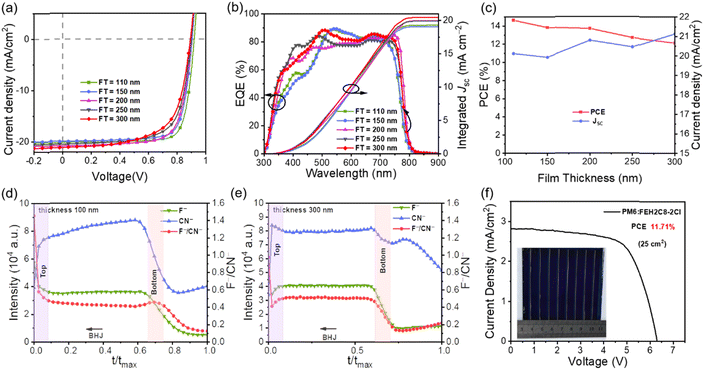
Developing thickness-insensitive OSCs is conducive to promoting the development of large-scale fabrication, where the devices' PCEs will decrease with an increase in film thickness, mainly owing to the dramatic loss of FF.41 Considering the high efficiency and outstanding FF, we fabricated a series of OSCs based on FEH2C8-2Cl with a film thickness from 110 to 300 nm to evaluate the thickness-dependence behaviours. All the detailed photovoltaic parameters of the devices with inverted structures are listed in Table 3. The optimized devices yielded the best PCE of 14.60% with a high FF of 79.04% under a thin film of 110 nm. With increasing thickness of the active layer, the Voc was slightly decreased owing to the severe nongeminate recombination,31 and FF was also reduced owing to the increasing series resistance and parallel resistance. The Jsc decreased slightly and then increased (Fig. 5c) owing to the enhanced absorption of the active layer and efficient EQE response (Fig. 5b). Ultimately, a PCE of 12.14% was obtained with an active layer thickness of 300 nm. Notably, the results indicate the good thickness-insensitive properties of FEH2C8-2Cl-based devices, showing great potential for large-scale fabrication.42| Thickness (nm) | V oc (V) | J sc (mA cm−2) | J EQEsc (mA cm−2) | FF (%) | PCE (%) |
|---|---|---|---|---|---|
| 110 | 0.918 | 20.12 | 19.56 | 79.04 | 14.60 |
| 150 | 0.904 | 19.93 | 19.34 | 76.93 | 13.86 |
| 220 | 0.899 | 20.79 | 20.30 | 73.44 | 13.73 |
| 255 | 0.897 | 20.45 | 20.22 | 69.33 | 12.72 |
| 300 | 0.892 | 21.13 | 20.79 | 64.43 | 12.14 |
To understand the mechanism of the thick film tolerance, we performed the time-of-flight secondary ion mass spectrometry (TOF-SIMS) of the active layer films at the thicknesses of 110 nm and 300 nm to study the vertical phase distribution.43,44 The samples were prepared on an ITO/ZnO/NMA substrate similar to the inverted structure device. In the active layer, F− is the unique element of the donor PM6, while CN− is the unique group of the acceptor FEH2C8-2Cl. Therefore, the F−/CN− intensity radio variation could represent the relative distribution of the donor and acceptor in the vertical direction. As depicted in Fig. 5d, for the blend where the thickness is 100 nm, it was obvious that the acceptor gathered more at the bottom, which is favoured for the inverted structure device. However, in the 300 nm thickness blend (Fig. 5e), the F−/CN− intensity radio remained in a similar distribution from the top to the bottom, and there is no favoured vertical separation of the thin films. Fortunately, there was also no unfavoured vertical phase separation for the inverted structure devices, i.e. acceptor accumulated distribution on the top electrode side and donor accumulated distribution on the bottom ITO side. The above vertical phase separation might be one of the reasons that the device has a decreasing FF with increasing active layer thickness.
The above results demonstrate that the PM6:FEH2C8-2Cl blend is a good candidate for a large-area module device. Then, we fabricated a module comprising seven sub-cells connected in series with an active area of 25 cm2 (Fig. 5f). After optimization, the module provides the best PCE of 11.71%, with a VOC of 6.307 V, a Jsc of 2.810 mA cm−2, and an FF of 66.11%, which is among the high performance values for large area modules (Table S12†). The module retains 80% efficiency when the device area is scaled up from 0.04 cm2 (PCE = 14.60%) to 25 cm2. It is noteworthy that 11.71% of the above module has the highest efficiency for large-area OSCs fabricated with active layer materials other than Y6 and its derivatives.
3. Conclusions
In summary, we designed and synthesized two acceptors, FEH2C8-2Cl and F3EH-2Cl, via side-chain isomerization from an acceptor F-2Cl. Ultimately, the OSC based on FEH2C8-2Cl affords the best PCE of 14.60% with an excellent FF of 79.04%, a Voc of 0.918 V, and a Jsc of 20.12 mA cm−2. Moreover, FEH2C8-2Cl-based devices exhibit good active layer thickness tolerance. An efficiency of 12.14% can be obtained at a thickness of 300 nm, indicating the great potential for large-scale OSC fabrication. Encouragingly, a large-area module fabricated using FEH2C8-2Cl with an active area of 25 cm2 exhibited a PCE of 11.71%. These results show that side-chain isomerization is an efficient method to finely tune the molecular properties and then regulate the active layer morphology.Conflicts of interest
There are no conflicts of interest to declare.Acknowledgements
The author gratefully acknowledges the financial support from NSFC (52025033 and 21935007) MoST (2019YFA0705900) of China, Tianjin city (20JCZDJC00740), 111 Project (B12015) and the Haihe Laboratory of Sustainable Chemical Transformations.Notes and references
- C. Xie, X. Jiang, Q. Zhu, D. Wang, C. Xiao, C. Liu, W. Ma, Q. Chen and W. Li, Small Methods, 2021, 5, e2100481 CrossRef PubMed.
- F. Qin, L. Sun, H. Chen, Y. Liu, X. Lu, W. Wang, T. Liu, X. Dong, P. Jiang, Y. Jiang, L. Wang and Y. Zhou, Adv. Mater., 2021, 33, e2103017 CrossRef PubMed.
- H. Fu, J. Yao, M. Zhang, L. Xue, Q. Zhou, S. Li, M. Lei, L. Meng, Z. G. Zhang and Y. Li, Nat. Commun., 2022, 13, 3687 CrossRef CAS PubMed.
- H. Tang, J. Lv, K. Liu, Z. Ren, H. T. Chandran, J. Huang, Y. Zhang, H. Xia, J. I. Khan, D. Hu, C. Yan, J. Oh, S. Chen, S. Chu, P. W. K. Fong, H. Chen, Z. Xiao, C. Yang, Z. Kan, F. Laquai, S. Lu and G. Li, Mater. Today, 2022, 55, 46–55 CrossRef CAS.
- L. Meng, Y. Zhang, X. Wan, C. Li, X. Zhang, Y. Wang, X. Ke, Z. Xiao, L. Ding, R. Xia, H.-L. Yip, Y. Cao and Y. Chen, Science, 2018, 361, 1094–1098 CrossRef CAS.
- C. He, Y. Pan, Y. Ouyang, Q. Shen, Y. Gao, K. Yan, J. Fang, Y. Chen, C.-Q. Ma, J. Min, C. Zhang, L. Zuo and H. Chen, Energy Environ. Sci., 2022, 15, 2537–2544 RSC.
- L. Zhan, S. Li, Y. Li, R. Sun, J. Min, Y. Chen, J. Fang, C. Q. Ma, G. Zhou, H. Zhu, L. Zuo, H. Qiu, S. Yin and H. Chen, Adv. Energy Mater., 2022, 2201076 CrossRef CAS.
- R. Sun, Y. Wu, X. Yang, Y. Gao, Z. Chen, K. Li, J. Qiao, T. Wang, J. Guo, C. Liu, X. Hao, H. Zhu and J. Min, Adv. Mater., 2022, 34, e2110147 CrossRef PubMed.
- Y. Cui, Y. Xu, H. Yao, P. Bi, L. Hong, J. Zhang, Y. Zu, T. Zhang, J. Qin, J. Ren, Z. Chen, C. He, X. Hao, Z. Wei and J. Hou, Adv. Mater., 2021, 33, e2102420 CrossRef PubMed.
- Y. Zou, H. Chen, X. Bi, X. Xu, H. Wang, M. Lin, Z. Ma, M. Zhang, C. Li, X. Wan, G. Long, Z. Yao and Y. Chen, Energy Environ. Sci., 2022, 15, 3519–3533 RSC.
- X. Wan, C. Li, M. Zhang and Y. Chen, Chem. Soc. Rev., 2020, 49, 2828–2842 RSC.
- H. Chen, H. Liang, Z. Guo, Y. Zhu, Z. Zhang, Z. Li, X. Cao, H. Wang, W. Feng, Y. Zou, L. Meng, X. Xu, B. Kan, C. Li, Z. Yao, X. Wan, Z. Ma and Y. Chen, Angew. Chem., Int. Ed., 2022, 61, e202209580 CAS.
- Y. Liu, B. Liu, C.-Q. Ma, F. Huang, G. Feng, H. Chen, J. Hou, L. Yan, Q. Wei, Q. Luo, Q. Bao, W. Ma, W. Liu, W. Li, X. Wan, X. Hu, Y. Han, Y. Li, Y. Zhou, Y. Zou, Y. Chen, Y. Li, Y. Chen, Z. Tang, Z. Hu, Z.-G. Zhang and Z. Bo, Sci. China: Chem., 2021, 65, 224–268 CrossRef.
- L. Zhu, M. Zhang, J. Xu, C. Li, J. Yan, G. Zhou, W. Zhong, T. Hao, J. Song, X. Xue, Z. Zhou, R. Zeng, H. Zhu, C. C. Chen, R. C. I. MacKenzie, Y. Zou, J. Nelson, Y. Zhang, Y. Sun and F. Liu, Nat. Mater., 2022, 21, 656–663 CrossRef CAS PubMed.
- Z. Zheng, J. Wang, P. Bi, J. Ren, Y. Wang, Y. Yang, X. Liu, S. Zhang and J. Hou, Joule, 2022, 6, 171–184 CrossRef CAS.
- J. Gao, N. Yu, Z. Chen, Y. Wei, C. Li, T. Liu, X. Gu, J. Zhang, Z. Wei, Z. Tang, X. Hao, F. Zhang, X. Zhang and H. Huang, Adv. Sci., 2022, e2203606 CrossRef PubMed.
- Y. Wei, Z. Chen, G. Lu, N. Yu, C. Li, J. Gao, X. Gu, X. Hao, G. Lu, Z. Tang, J. Zhang, Z. Wei, X. Zhang and H. Huang, Adv. Mater., 2022, 34, e2204718 CrossRef PubMed.
- S. Guan, Y. Li, K. Yan, W. Fu, L. Zuo and H. Chen, Adv. Mater., 2022, e2205844 CrossRef PubMed.
- Z. Yin, X. Guo, Y. Wang, L. Zhu, Y. Chen, Q. Fan, J. Wang, W. Su, F. Liu, M. Zhang and Y. Li, Chem. Eng. J., 2022, 442, 136018 CrossRef CAS.
- C. Zhang, S. Feng, Y. Liu, R. Hou, Z. Zhang, X. Xu, Y. Wu and Z. Bo, Acs Appl. Mater. Interfaces, 2017, 9, 33906–33912 CrossRef CAS PubMed.
- A. Shang, S. Luo, J. Zhang, H. Zhao, X. Xia, M. Pan, C. Li, Y. Chen, J. Yi, X. Lu, W. Ma, H. Yan and H. Hu, Sci. China: Chem., 2022, 65, 1758–1766 CrossRef CAS.
- C. Li, J. Zhou, J. Song, J. Xu, H. Zhang, X. Zhang, J. Guo, L. Zhu, D. Wei, G. Han, J. Min, Y. Zhang, Z. Xie, Y. Yi, H. Yan, F. Gao, F. Liu and Y. Sun, Nat. Energy, 2021, 6, 605–613 CrossRef CAS.
- D. Luo, Z. Jiang, C. Shan, L. Li, C. Duan, Q. Liu, Z. Wang, K. Wang, B. Xu and A. K. K. Kyaw, Acs Appl. Mater. Interfaces, 2022, 14, 24374–24385 CrossRef CAS.
- M. Chang, L. Meng, Y. Wang, X. Ke, Y.-Q.-Q. Yi, N. Zheng, W. Zheng, Z. Xie, M. Zhang, Y. Yi, H. Zhang, X. Wan, C. Li and Y. Chen, Chem. Mater., 2020, 32, 2593–2604 CrossRef CAS.
- S. Jeong, B. Park, S. Hong, S. Kim, J. Kim, S. Kwon, J. H. Lee, M. S. Lee, J. C. Park, H. Kang and K. Lee, ACS Appl. Mater. Interfaces, 2020, 12, 41877–41885 CrossRef CAS PubMed.
- H. Zhao, B. Lin, J. Xue, H. B. Naveed, C. Zhao, X. Zhou, K. Zhou, H. Wu, Y. Cai, D. Yun, Z. Tang and W. Ma, Adv. Mater., 2022, 34, e2105114 CrossRef PubMed.
- Y. Cai, Q. Li, G. Lu, H. S. Ryu, Y. Li, H. Jin, Z. Chen, Z. Tang, G. Lu, X. Hao, H. Y. Woo, C. Zhang and Y. Sun, Nat. Commun., 2022, 13, 2369 CrossRef CAS PubMed.
- J. Qin, L. Zhang, Z. Xiao, S. Chen, K. Sun, Z. Zang, C. Yi, Y. Yuan, Z. Jin, F. Hao, Y. Cheng, Q. Bao and L. Ding, Sci. Bull., 2020, 65, 1979–1982 CrossRef CAS.
- Z. Zhou, S. Xu, J. Song, Y. Jin, Q. Yue, Y. Qian, F. Liu, F. Zhang and X. Zhu, Nat. Energy, 2018, 3, 952–959 CrossRef CAS.
- H. R. Bai, Q. An, M. Jiang, H. S. Ryu, J. Yang, X. J. Zhou, H. F. Zhi, C. Yang, X. Li, H. Y. Woo and J. L. Wang, Adv. Funct. Mater., 2022, 32, 2200807 CrossRef CAS.
- H. Wang, Z. Zhang, J. Yu, X. Liu and W. Tang, Chem. Eng. J., 2021, 418, 129539 CrossRef CAS.
- Y. Li, L. Yu, L. Chen, C. Han, H. Jiang, Z. Liu, N. Zheng, J. Wang, M. Sun, R. Yang and X. Bao, Innovation, 2021, 2, 100090 Search PubMed.
- Y. Zhang, H. Feng, L. Meng, Y. Wang, M. Chang, S. Li, Z. Guo, C. Li, N. Zheng, Z. Xie, X. Wan and Y. Chen, Adv. Energy Mater., 2019, 9, 1902688 CrossRef CAS.
- B. Kan, X. Wan, C. Li and Y. Chen, Acta Polym. Sin., 2021, 52, 1262–1282 Search PubMed.
- Q. An, J. Wang, W. Gao, X. Ma, Z. Hu, J. Gao, C. Xu, M. Hao, X. Zhang, C. Yang and F. Zhang, Sci. Bull., 2020, 65, 538–545 CrossRef CAS.
- K. Ding, T. Shan, J. Xu, M. Li, Y. Wang, Y. Zhang, Z. Xie, Z. Ma, F. Liu and H. Zhong, Chem. Commun., 2020, 56, 11433–11436 RSC.
- Z. Zheng, Q. Hu, S. Zhang, D. Zhang, J. Wang, S. Xie, R. Wang, Y. Qin, W. Li, L. Hong, N. Liang, F. Liu, Y. Zhang, Z. Wei, Z. Tang, T. P. Russell, J. Hou and H. Zhou, Adv. Mater., 2018, 30, e1801801 CrossRef PubMed.
- Y. Wang, Y. Wang, B. Kan, X. Ke, X. Wan, C. Li and Y. Chen, Adv. Energy Mater., 2018, 8, 1702870 CrossRef.
- J. Sworakowski, Synth. Methods, 2018, 235, 125–130 CrossRef CAS.
- S. Li, Q. Fu, L. Meng, X. Wan, L. Ding, G. Lu, G. Lu, Z. Yao, C. Li and Y. Chen, Angew. Chem., Int. Ed., 2022, 61, e202207397 CAS.
- L. Ma, S. Zhang, H. Yao, Y. Xu, J. Wang, Y. Zu and J. Hou, Acs Appl. Mater. Interfaces, 2020, 12, 18777–18784 CrossRef CAS.
- S. Park, T. Kim, S. Yoon, C. W. Koh, H. Y. Woo and H. J. Son, Adv. Mater., 2020, 32, e2002217 CrossRef PubMed.
- S. Liu, D. Chen, X. Hu, Z. Xing, J. Wan, L. Zhang, L. Tan, W. Zhou and Y. Chen, Adv. Funct. Mater., 2020, 30, 2003223 CrossRef CAS.
- L. Zhan, S. Li, X. Xia, Y. Li, X. Lu, L. Zuo, M. Shi and H. Chen, Adv. Mater., 2021, 33, e2007231 CrossRef PubMed.
Footnotes |
| † Electronic supplementary information (ESI) available. See DOI: https://doi.org/10.1039/d2ta08301a |
| ‡ These authors contributed equally to this work. |
| This journal is © The Royal Society of Chemistry 2023 |

