Dynamic hydrogen bubbling templated AgSn@SnOx electrocatalyst for selective electrochemical CO2 reduction: adjusting the binding energy of the HCOO* intermediate†
Hisham G.
El-Aqapa
a,
Ibrahim M.
Badawy
 a,
Ghada E.
Khedr
 ab,
Ahmed M.
Agour
a,
Doha M.
Sayed
ac,
Manar M.
Taha
a and
Nageh K.
Allam
 *a
*a
aEnergy Materials Laboratory (EML), School of Sciences and Engineering, The American University in Cairo, New Cairo 11835, Egypt. E-mail: nageh.allam@aucegypt.edu
bDepartment of Analysis and Evaluation, Egyptian Petroleum Research Institute, Cairo, Egypt
cDepartment of Chemistry, Faculty of Science, Cairo University, Cairo 12613, Egypt
First published on 7th August 2023
Abstract
Core–shell AgSn@SnOx electrodes prepared via dynamic hydrogen bubbling templating and galvanic replacement demonstrated selective electrocatalytic reduction of CO2 towards HCOOH with a faradaic efficiency of 96 ± 4.9% and partial current density of −10.46 ± 0.35 mA cm−2. DFT calculations revealed that the catalyst expedites the production of formic acid via adjusting the binding energy of the HCOO* intermediate.
Given the growing concern over climate change, the replacement of fossil fuels with greener alternatives is a must.1,2 Continuously rising temperature levels have left little leeway for how much carbon dioxide (CO2) emissions the globe can tolerate.2,3 One attractive solution is the conversion of CO2 into value-added chemicals. To achieve this, appropriate catalysts are needed to reduce the activation energy barrier for such reactions, which will ultimately minimize the amount of energy required for the CO2 reduction reaction (CO2RR). An important subject matter for the CO2RR is determining which product is ideal for large scale production. Many techno-economic analyses argue that C1 (CO and formate) products hold the best economic feasibility, which involve only 2-electron transfer.4–6 Generally, these products involve the lowest overpotential with an already demonstrated high faradaic efficiency (FE) exceeding 80% using metal electrocatalysts such as Sn,7–9 Ag,10 Zn,11–13 Bi,7,14–16 and Co.17,18
To achieve higher FEs, however, different material design strategies must be undertaken. Among these strategies, core–shell structures offer compelling results. Pérez et al. prepared SnIn@InSnOx nanoparticles for the CO2RR with an 80% FE for formate production, which was ascribed to the In-rich surface of the catalyst.19 In another study, Luc et al. manipulated the shell thickness of AgSn/SnOx to optimize the performance of the catalyst to 80% FE for formate.20 The authors argued that the shell thickness affected the stabilization of *CO2˙−, which is correlated to formate production, largely due to the electronic and lattice changes in the material. In general, core–shell structures offer wide versatility, high conductivity, and high surface area, in which all produce high performance electrocatalysts for the CO2RR. To design these catalysts, however, many complicated multi-step synthesis techniques that rely on seed generation and growth have to be employed, which hinders their large-scale implementation.21 Herein, we demonstrate a facile, two-step synthesis of AgSn@SnOx core–shell structures using electrodeposition and galvanic displacement for the selective production of formate. The synthesized catalyst adjusted the binding energy of the HCOO* intermediate, leading to formate production with a 96% FE and −10.5 mA cm−2 partial current density.
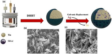
The synthesis of the AgSn@SnOx catalysts involves dynamic hydrogen bubbling template (DHBT) electrodeposition and galvanic replacement, Fig. 1a. The first step includes the galvanostatic electrodeposition of Sn from a SnCl4 solution on copper foil, resulting in the formation of porous dendrite structures of Sn on the surface as shown in Fig. 1b. Afterwards, the Sn film was dipped in a solution of AgNO3 to produce a AgSn alloy (eqn (1)). An ultrathin SnOx layer is generated spontaneously when the samples are exposed to air.
| Ag+ + Sn0 → AgSn@SnOx + Snn+ | (1) |
 | ||
| Fig. 1 (a) Synthesis steps of the AgSn@SnOx catalyst and (b) SEM images of Sn@SnOx and (c) AgSn@SnOx (30 s). | ||
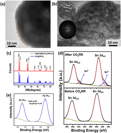
Fig. 2a shows the high resolution transmission electron microscopy (HRTEM) images of the synthesized AgSn@SnOx, revealing the core–shell structure of the AgSn alloy along with an ultrathin layer of SnOx with an average thickness of 3.55 nm. Both the Sn and Ag metals have different surface energies. This drives the spontaneous diffusion of bulk Sn atoms to the surface, where they are subsequently oxidized into a layer of SnOx as they come into contact with air. The overall result of the Sn atoms' behaviour is that less Ag atoms are detected on the surface (compared to the bulk) despite the galvanic displacement reaction as listed in Table 1.22 Additionally, some neighbouring lattice fringes (Fig. 2b) show a diffraction spacing of 0.259 nm, verifying the formation of an intermetallic AgSn (110) phase in the bulk.23 The X-ray diffraction (XRD) patterns (Fig. 2c) revealed no metal oxide phases, confirming the amorphous nature of the SnOx shell. As for the X-ray photoelectron spectroscopy (XPS) measurements, the survey spectrum (Fig. S1†) shows three peaks corresponding to O1s, Ag 3d, and Sn 3d. The O1s spectrum (Fig. S1†) shows three peaks at binding energies of 531.33, 532.51, and 533.64 eV, corresponding to (Ov), (Sn–O), and adsorbed oxygen species, respectively.24 The deconvolution of the Sn 3d spectrum generates two peaks characteristic of Sn4+/2+ (487.88 and 496.28 eV).25 It is worth mentioning that the absence of Sn0 peaks is likely due to the ex situ XPS measurement that results in excessive oxidation of the sample upon exposure to air for a long time; thus, the oxide species peaks overlapped with the metallic Sn0 peaks. As for the Ag 3d spectrum (368.7 eV and 374.82 eV), it exhibits no oxide species, which indicates that the surface is predominantly covered with SnOx. The elemental composition of the bulk and surface is further investigated via XPS and energy dispersive X-ray spectroscopy (EDX). Each technique measured the elemental distribution at a unique penetration depth.26 XPS data (Table 1) show a lower atomic percentage of Ag compared to that from EDX analysis, leading to the conclusion that Ag diffuses into the bulk during the synthesis.
| Elemental analysis technique | Sn | O | Ag |
|---|---|---|---|
| EDX | 88% | 4% | 8% |
| XPS | 58.96% | 40.68% | 0.35% |
The electrochemical CO2 reduction activity of AgSn@SnOx (30 s) was examined using linear sweep voltammetry (LSV) in CO2-saturated 0.1 M KHCO3 and N2-saturated 0.1 M Na2SO4. The pH under both conditions was confirmed to be the same (pH = 7.2). The onset potential in the case of CO2 purging was measured to be less negative (−0.624 V vs. RHE) compared to that under N2 purging conditions (−0.928 V vs. RHE). This likely indicates the electrochemical selectivity of AgSn@SnOx (30 s) towards CO2 reduction instead of the hydrogen evolution reaction (HER) with a potential difference of 304 mV. Fig. S2† shows a positive shift in the onset potential of AgSn@SnOx (30 s) compared to that of bare Sn, indicating the formation of a new bulk Ag–Sn intermetallic phase rather than a simple interfacial alloy with superior catalytic activity towards CO2 reduction.27
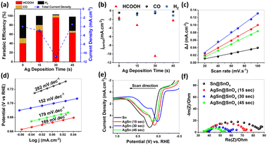
The electrocatalytic performance of the different samples was further investigated at different overpotentials, Fig. S3.† We observed a volcano-like relationship between the galvanic replacement time and the faradaic efficiencies (FEs) and the partial current densities of HCOOH as shown in Fig. 3a and b. The maximum was observed at −0.9 V vs. RHE. The AgSn@SnOx (30 s) catalyst showed selectivity towards HCOOH with a FE of 96 ± 4.9% and partial current density of −10.46 ± 0.35 mA cm−2. In contrast, the pure Sn catalyst exhibited weaker CO2RR performance (FE = 40.41% ± 8.90) under the same operating conditions. This enhancement likely originates from the superior surface roughness of AgSn@SnOx, which can boost CO2 gas–surface interactions, resulting in higher catalytic efficiency. Moreover, the AgSn@SnOx catalysts showed negligible HER activity, while the Sn catalyst showed a modest suppression of the HER (50.53% ± 3.41). The HER is the main competitive reaction in CO2 electrolysis. On the other hand, the AgSn@SnOx catalysts showed a plateau of the CO FE, despite the presence of an efficient CO promoter (i.e. Ag metal). This finding provides strong evidence that the surface is predominantly covered by a SnOx shell instead of Ag.
The capacitive behavior of each sample was examined in order to study the intrinsic electrocatalytic activity of each sample. The double layer capacitance (Cdl), derived from cyclic voltammetry scanned in the non-faradaic region (Fig. S4†), showed the following trend: AgSn@SnOx (30 s; 1280.41 μF cm−2) > AgSn@SnOx (15 s; 1000.35 μF cm−2) > AgSn@SnOx (45 s; 858.12 μF cm−2) > Sn@SnOx (359.34 μF cm−2) as depicted in Fig. 3c. These results support the observed volcanic electrocatalytic performance. However, the jHCOOH normalized by the electrochemical active surface area (ESCA) manifests a similar trend to the uncorrected jHCOOH, indicating the minor impact of the ESCA on the catalytic performance.28 Furthermore, AgSn@SnOx (30 s) produced a plateau current density of 10 mA cm−2 with a FEHCOOH of 87.46%@−0.9 V after 1800 min of electrolysis (Fig. S5†). The XPS spectrum of Sn 3d after the CO2RR showed metallic Sn peaks at 485.31 and 493.79 eV, indicating the partial reduction of the SnOx layer during the CO2RR process.
The CO2RR has a complicated mechanism that involves sluggish kinetic limitations related to the charge transfer and the geometrical changes of CO2 molecules at the electrode–electrolyte interface.29 Tafel analysis is the best choice to investigate the mechanistic pathways and elucidate the rate-determining step in the CO2 reduction process. Among all samples, AgSn@SnOx (30 s) displayed the lowest Tafel slope (152 mV dec−1), verifying the faster reaction kinetics compared to its counterparts, as depicted in Fig. 3d. This value is a staunch indicator of *CO2˙− radical intermediate formation in the first electron transfer step.30 With that in mind, the CO2 reduction mechanism is controlled by other factors such as the operating potential and mass transport limitations that provide a more accurate manifestation of the mechanism, so these might be discussed in the future.
Moreover, we conducted oxidative LSV to determine the adsorption affinity of HO− anions as a surrogate to *CO2˙− radicals on different samples (Fig. 3d).31,32 The results demonstrated the coincidence between the kinetic findings of Tafel analysis and the adsorption affinity of HO− anions on the different surfaces, indicating the better performance of AgSn@SnOx (30 s) relative to the other samples, with the lowest adsorption energy of 0.015 V. These findings are attributed to the in situ formation of oxygen vacancies under the used cathodic conditions (i.e., partial reduction of the oxide layer). This, in turn, stabilizes the *CO2˙− radicals, and results in a lower binding energy. Furthermore, EIS was used to uncover the origin of the bulk component–charge transfer relationship within the different catalysts. Nyquist plots (Fig. 3e) revealed a considerable enhancement in the charge transfer, leading to the conclusion that silver atoms diffuse to the bulk, forming a Ag–Sn intermetallic phase that immensely ameliorates the conductivity of the bulk with respect to that of pure Sn.
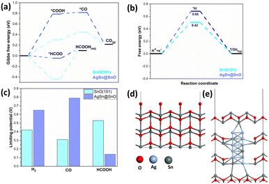
In fact, there are other factors that can verify the catalytic activity such as the surface energetics and the optimal binding energy of the intermediate on the surface. To this end, DFT calculations were conducted to investigate the influence of the AgSn@SnOx core shell on the CO2 reduction reaction (CO2RR) activity. Fig. 4a illustrates the calculated Gibbs free energy changes for the CO2RR and its corresponding adsorption intermediates. The formation of the HCOO* intermediate was found to be exothermic, whereas the formation process of *COOH was determined to be endothermic. Consequently, in the production of formic acid, the HCOO hydrogenation step sets the limiting potential. In contrast, in the production of CO, the rate-determining step is the formation of COOH.33 The implementation of the AgSn@SnOx core shell lowers the binding strength of the HCOO* intermediate relative to its counterpart on SnO (101), resulting in a decrease in the rate-determining step for formic acid production and an increase in the limiting potential for CO generation at the AgSn@SnOx core shell.
Additionally, a Gibbs free energy diagram for the hydrogen evolution reaction (HER) process (Fig. 4b) was established, along with the corresponding structures of reaction intermediates, demonstrating that the AgSn@SnOx core shell effectively suppresses hydrogen evolution by weakening the attachment of *H intermediates. In Fig. 4c, the limiting potential of each product in both systems is shown. In the case of the AgSn@SnOx catalyst, the rate-determining step for producing formic acid is the lowest among the three products, referring to its prominence as the main product of the CO2RR. Notably, the AgSn@SnOx catalyst exhibits a further reduction in the rate-determining step for producing formic acid, while the limiting potentials for CO and H2 generation are increased compared that for SnO (101). Therefore, based on the DFT calculations, implementing the AgSn@SnOx core–shell structure enhances the selectivity for both formic acid and C1 products. The optimized geometries for SnO (101) and AgSn@SnOx are shown, for clarification, in Fig. 4d and e, respectively.
To conclude, a facile electrochemical synthesis of 3D hierarchical porous AgSn@SnOx core–shell catalysts has been demonstrated as efficient candidates for CO2 reduction to formate. The AgSn@SnOx (30 s) catalyst showed excellent selectivity towards formate (FEHCOOH = 96% ± 4.90; jHCOOH = −10.5 mA cm−2 at −0.9 vs. RHE) with negligible HER activity. Tafel analysis and adsorption affinity studies suggest that AgSn@SnOx (30 s) has faster reaction kinetics and the lowest adsorption energy, implying the formation of oxygen vacancies under cathodic conditions, which stabilize *CO2˙− radicals and achieve lower binding energy. DFT calculations showed that the AgSn@SnOx core–shell structure accelerates the formation of formic acid by modifying the binding energy of the HCOO*intermediate. Additionally, this structure improved the faradaic efficiency of C1 production by suppressing the competitive hydrogen evolution reaction (HER), which is considered the main side reaction in the CO2RR. The AgSn@SnOx catalyst stands out as one of the most efficient electrocatalysts for CO2 reduction to formate, when compared to other formate-selective electrocatalysts (Fig. S9, Table S3†). It demonstrated superior performance in terms of formate partial current density and formate faradaic efficiency. All in all, AgSn@SnOx core–shell catalysts showed great potential for efficient CO2 reduction to formate, which could have significant implications for sustainable energy production.
Conflicts of interest
There are no conflicts to declare.Acknowledgements
The financial support by the American University in Cairo is highly appreciated.Notes and references
- M. Falkenberg, A. Galeazzi, M. Torricelli, N. Di Marco, F. Larosa, M. Sas, A. Mekacher, W. Pearce, F. Zollo, W. Quattrociocchi and A. Baronchelli, Nat. Clim. Change, 2022, 12, 1114–1121 CrossRef.
- W. Sharmoukh and H. N. Abdelhamid, Fenton-like Cerium Metal–Organic Frameworks (Ce-MOFs) for Catalytic Oxidation of Olefins, Alcohol, and Dyes Degradation, J. Cluster Sci., 2023, 34, 2509–2519 CrossRef CAS.
- X. Wang, Q. Chen, Y. Zhou, Y. Tan, Y. Wang, H. Li, Y. Chen, M. Sayed, R. A. Geioushy, N. K. Allam, J. Fu, Y. Sun and M. Liu, Nano Research, 2023 DOI:10.1007/s12274-023-5910-9.
- M. Jouny, W. Luc and F. Jiao, Ind. Eng. Chem. Res., 2018, 57, 2165–2177 CrossRef CAS.
- O. S. Bushuyev, P. De Luna, C. T. Dinh, L. Tao, G. Saur, J. van de Lagemaat, S. O. Kelley and E. H. Sargent, Joule, 2018, 2, 825–832 CrossRef CAS.
- M. G. Kibria, J. P. Edwards, C. M. Gabardo, C. T. Dinh, A. Seifitokaldani, D. Sinton and E. H. Sargent, Adv. Mater., 2019, 31, 1807166 CrossRef PubMed.
- G. Wen, D. U. Lee, B. Ren, F. M. Hassan, G. Jiang, Z. P. Cano, J. Gostick, E. Croiset, Z. Bai, L. Yang and Z. Chen, Adv. Energy Mater., 2018, 8, 1802427 CrossRef.
- T. Wang, J. Chen, X. Ren, J. Zhang, J. Ding, Y. Liu, K. H. Lim, J. Wang, X. Li, H. Yang, Y. Huang, S. Kawi and B. Liu, Angew. Chem., Int. Ed., 2023, 62, e202211174 CAS.
- X. Zhong, S. Liang, T. Yang, G. Zeng, Z. Zhong, H. Deng, L. Zhang and X. Sun, ACS Nano, 2022, 16, 19210–19219 CrossRef CAS PubMed.
- X. Deng, D. Alfonso, T. D. Nguyen-Phan and D. R. Kauffman, ACS Catal., 2022, 5921–5929 CrossRef CAS.
- I. M. Badawy, A. M. Ismail, G. E. Khedr, M. M. Taha and N. K. Allam, Sci. Rep., 2022, 12, 13456 CrossRef CAS PubMed.
- M. Morimoto, Y. Takatsuji, K. Hirata, T. Fukuma, T. Ohno, T. Sakakura and T. Haruyama, Electrochim. Acta, 2018, 290, 255–261 CrossRef CAS.
- J. Zeng, T. Rino, K. Bejtka, M. Castellino, A. Sacco, M. A. Farkhondehfal, A. Chiodoni, F. Drago and C. F. Pirri, ChemSusChem, 2020, 13, 4128–4139 CrossRef CAS PubMed.
- C. J. Peng, X. T. Wu, G. Zeng and Q. L. Zhu, Chem. – Asian J., 2021, 16, 1539–1544 CrossRef CAS PubMed.
- Y. Zhang, C. Cao, X. T. Wu and Q. L. Zhu, Inorg. Chem. Front., 2021, 8, 2461–2467 RSC.
- X. An, S. Li, A. Yoshida, T. Yu, Z. Wang, X. Hao, A. Abudula and G. Guan, ACS Appl. Mater. Interfaces, 2019, 11, 42114–42122 CrossRef CAS PubMed.
- R. Daiyan, R. Chen, P. V. Kumar, N. M. Bedford, J. Qu, J. M. Cairney, X. Lu and R. Amal, ACS Appl. Mater. Interfaces, 2020, 12, 9307–9315 CrossRef CAS PubMed.
- J. Huang, X. Guo, G. Yue, Q. Hu and L. Wang, ACS Appl. Mater. Interfaces, 2018, 10, 44403–44414 CrossRef CAS PubMed.
- L. C. Pardo Pérez, D. Teschner, E. Willinger, A. Guiet, M. Driess, P. Strasser and A. Fischer, Adv. Funct. Mater., 2021, 31, 2103601 CrossRef.
- W. Luc, C. Collins, S. Wang, H. Xin, K. He, Y. Kang and F. Jiao, J. Am. Chem. Soc., 2017, 139, 1885–1893 CrossRef CAS PubMed.
- Q. Shao, P. Wang, S. Liu and X. Huang, J. Mater. Chem. A, 2019, 7, 20478–20493 RSC.
- L. Vitos, A. V. Ruban, H. L. Skriver and J. Kollár, Surf. Sci., 1998, 411, 186–202 CrossRef CAS.
- W. Luc, C. Collins, S. Wang, H. Xin, K. He, Y. Kang and F. Jiao, J. Am. Chem. Soc., 2017, 139, 1885–1893 CrossRef CAS PubMed.
- X. Zhao, Y. Wang, L. Zhan, M. Liu, J. Wu, D. Deng, J. Jiang, X. Zheng, X. Xiong and Y. Lei, Chem. Commun., 2022, 58, 12716–12719 RSC.
- H. Li, N. Xiao, Y. Wang, C. Liu, S. Zhang, H. Zhang, J. Bai, J. Xiao, C. Li, Z. Guo, S. Zhao and J. Qiu, J. Mater. Chem. A, 2020, 8, 1779–1786 RSC.
- I. M. Badawy, G. E. Khedr, A. Hafez, E. A. Ashour and N. K. Allam, Chem. Commun., 2023, 59, 7974–7977 RSC.
- A. M. Ismail, G. F. Samu, Á. Balog, E. Csapó and C. Janáky, ACS Energy Lett., 2019, 4, 48–53 CrossRef CAS.
- Y. Li, K. Zhang, Y. Yu, X. Zhan, J. Gui, J. Xue, X. Jin, S. Gao and Y. Xie, Chem. Commun., 2022, 58, 387–390 RSC.
- T. K. Todorova, M. W. Schreiber and M. Fontecave, ACS Catal., 2020, 10, 1754–1768 CrossRef CAS.
- R. Daiyan, X. Lu, Y. H. Ng and R. Amal, Catal. Sci. Technol., 2017, 7, 2542–2550 RSC.
- N. B. Watkins, Z. J. Schiffer, Y. Lai, C. B. III. Musgrave, H. A. Atwater, W. A. III. Goddard, T. Agapie, J. C. Peters and J. M. Gregoire, ACS Energy Lett., 2023, 8, 2185–2192 CrossRef CAS.
- S. Zhang, P. Kang and T. J. Meyer, J. Am. Chem. Soc., 2014, 136, 1734–1737 CrossRef CAS PubMed.
- A. M. Hafez, A. F. Zedan, S. Y. AlQaradawi, N. M. Salem and N. K. Allam, Energy Convers. Manage., 2016, 122, 207–214 CrossRef CAS.
Footnote |
| † Electronic supplementary information (ESI) available. See DOI: https://doi.org/10.1039/d3cy00939d |
| This journal is © The Royal Society of Chemistry 2023 |


