
Metal–organic-framework embellished through ion etching method for highly enhanced electrochemical oxygen evolution reaction catalysis†
Qiuxiang
Mou
a,
Zhenhang
Xu
b,
Wei
Zuo
b,
Tianyu
Shi
b,
Erlei
Li
a,
Gongzhen
Cheng
 b,
Xinghai
Liu
a,
Huaming
Zheng
*c,
Houbin
Li
*a and
Pingping
Zhao
*a
b,
Xinghai
Liu
a,
Huaming
Zheng
*c,
Houbin
Li
*a and
Pingping
Zhao
*a
aResearch Center for Graphic Communication, Printing and Packaging, Wuhan University, Wuhan, Hubei 430072, P. R. China. E-mail: lhb@whu.edu.cn; ppzhao@whu.edu.cn
bCollege of Chemistry and Molecular Sciences, Wuhan University Wuhan, Hubei 430072, P. R. China
cSchool of Material Sciences & Engineering, Wuhan Institute of Technology, Wuhan, 430073, Hubei, P. R. China. E-mail: hmz_416@wit.edu.cn
First published on 3rd August 2022
Abstract
Metal–organic-frameworks (MOFs) are scarcely considered to catalyse electrochemical reactions directly due to the limitation of their bulk structure, poor conductivity, and scarce active sites. Fe ions, as effective activity boosters for nickel-based catalysts, can effectively modulate the neatly arranged structure and electron configuration of MOF materials through the penetrating and etching process. Therefore, a Fe ion etching method was employed to modulate the structure and electronic configuration of bulk MOF. The resulting Ni-MOF-Fe-2 was equipped with a wider pore width distribution and lower crystallinity, and the Fe ion doping induced many dislocations and stacking faults in the lattice planes, which provided sufficient defects and active sites for OER. Therefore, Ni-MOF-Fe-2 displayed an advanced performance with an overpotential of 269 mV at the current density of 10 mA cm−2, and the small Tafel slope of 47.1 mV dec−1 and charge transfer resistances (Rct) of 8.31 Ω revealed its fast kinetics and high electron transfer efficiency, indicating that Fe ion etching played an important role in booting OER performance of Ni MOF.
Introduction
With the increasing energy crisis and environmental pollution, developing new technology for efficient and environment-friendly energy conversion and storage is crucial.1,2 Hydrogen (H2), the cleanest fuel available, is the optimal candidate to meet these needs of future society due to its high energy density and energy conversion efficiency.3–5 Among the various methods of hydrogen production, water splitting has attracted increasing attention due to its abundant feedstock, high product purity, environmental friendliness, and considerable sustainability.6–9 Although the water splitting devices are made to produce hydrogen rather than oxygen, the oxygen evolution reaction (OER) has become a dominant factor limiting the efficiency of water oxidation due to its sluggish kinetics.10–12 In the early stages, proton exchange membrane (PEM) water electrolyzers and alkaline water electrolyzers both used noble metal oxides IrO2 and RuO2 to catalyze OER, but they are limited by high cost and their instability under acidic conditions.13,14 Therefore, developing efficient, earth-abundant and stable OER catalysts has become an urgent global problem in recent years.Metal organic frameworks (MOFs) are a kind of crystalline materials with periodically arranged network structure.15–17 Their porous structure facilitates the penetration of electrolytes and the accessibility of reaction substances, which is ideal for transition metal carriers and efficient catalysts.18,19 In general, however, MOF has poor conductivity and poor stability at the voltages required for electrochemical reactions.20 Thus, derivatives of transition metal-based MOFs are considered ideal alternatives due to their promising catalytic activity, outstanding stability, and abundant resources, and these include oxides, sulfides, nitrides, phosphides, etc.21–25 Moreover, transition metal compounds are considered to achieve easier electron transfer due to multiple oxidation states,26–28 thus enhancing catalytic activity. There are few reports about MOFs acting as electrochemical catalysts directly. In order to promote their electrical conductivity, MOFs are combined with conductive carriers to enhance the electrical conductivity of MOF, including nickel foam,29,30 carbon dots,31,32 and graphene.33,34 Among these MOFs, nickel-based MOFs have attracted increasing attention due to Ni ions’ inherent OER catalytic activity.35–37 Using MOFs as electrocatalysts directly will be a significant and highly desirable challenge for this project.
Herein, the Fe ion etching of nickel based bulk MOF, Ni-MOF-Fe-2, was designed and tested. The introduction of iron ions into nickel-based catalysts can substantially contribute to OER performance. Iron ions, as a kind of Lewis acid, can generate H+ through hydrolysis, which can penetrate and etch the originally neatly arranged structure of MOF during the reaction, and it is an effective means to regulate the morphology of MOF-based catalysts.38–40 Therefore, it is a promising approach to design remarkable catalysts that boosts OER performances by doping iron into nickel-based catalysts through the solvothermal process. Compared with pristine MOF, the Fe ion doped sample featured lower crystallinity caused by the deformed lattice plane, resulting in various defects that facilitated its OER activities. XPS results showed the Fe ion modified catalysts were loaded with higher chemical valence state nickel ions, indicating its superior OER activity. As a result, Ni-MOF-Fe-2 delivered a current density of 10 mA cm−2 with an overpotential of only 269 mV, and it also showed excellent stability. EIS and Cdl results illustrated the Ni-MOF-Fe-2 was more favorable in conductivity and active sites, and the method provided a feasible attempt to promote OER activities of future MOF-based catalysts.
Experimental
Materials and chemicals
The chemicals used during the synthesis of catalysts (including nickel(II) nitrate hexahydrate [Ni(NO3)2·6H2O], iron(III) chloride hexahydrate (FeCl3·6H2O), formic acid (HCOOH), and N,N-dimethylformamide (DMF)) were purchased from Sinopharm Chemical Reagent Co., Ltd. Nafion solution (5 wt%) was purchased from Sigma-Aldrich. All the chemicals were directly used without any further refinement.Synthesis of Ni MOF
The precursor Ni MOF was synthesized with reference to previous work.41 3.402 g nickel(II) nitrate hexahydrate was dissolved in 15 mL DMF under ultrasonication. After adding 4.5 mL formic acid, the whole system was transferred into a 50 mL Teflon-lined autoclave and sealed, followed by a 12 h solvothermal treatment at 100 °C. After cooling down to room temperature, the pale green product was washed with ethyl alcohol 3 times and dried at 80 °C to prepare for the next step.Synthesis of Ni-MOF-Fe-x
The catalysts, Ni-MOF-Fe-x, were obtained by etching Ni MOF with different concentrations of iron ion solution. Consider Ni-MOF-Fe-2, for instance. 0.162 g iron(III) chloride hexahydrate was dissolved in 30 mL DMF to form a 0.02 M Fe3+ solution. Then, 50 mg of the precursor Ni MOF was added to the solution, transferred to a 50 mL Teflon-lined autoclave, and heated for 4 h at 100 °C in the oven. The product was washed with ethyl alcohol 3 times and dried at 80 °C. Ni-MOF-Fe-1 and Ni-MOF-Fe-3 were synthesized in the same way, except for changing the concentration of Fe3+ solution to 0.01 M and 0.03 M, respectively.Electrochemical measurements
All the electrochemical measurements were carried out on a CHI-760E electrochemical workstation with a three-electrode system in 1 M KOH. The catalyst, Pt, and Hg/HgO were chosen as the working electrode, counter electrode, and reference electrode, respectively. The catalyst ink was prepared by dispersing 5 mg catalyst in 1 mL Nafion solution (0.1 wt%) by a 30 min ultrasonication. Before loading the catalyst, the surface of the glassy carbon electrode (GCE, diameter = 5 mm) was polished with 1.5 μm, 500 nm, and 50 nm α-Al2O3 successively. After washing with ultrapure water and ethanol, 12 μL ink was dripped on the clean surface and dried at room temperature. The mass loading of the catalyst was calculated as 0.3 mg cm−2.To remove the unstable parts and activate the catalysts, 200 cyclic voltammetric scans (CVs) from a potential of 1.02 V to 1.82 V (vs. RHE) with a scan rate of 500 mV s−1 were taken prior to the measurement. The OER cyclic voltammetry (CV) scans were measured from the potential of 1.12 V to 1.77 V (vs. RHE) at the scan rate of 5 mV s−1, and the polarization curves were determined by the negative scan part of CV, and the overpotentials (η) were obtained from η = E(vs. RHE) − 1.23 V. All the curves were recorded without iR-correction.
The Tafel plots of catalysts were depicted from their corresponding linear sweep voltammograms (LSV) data, which can be fitted based on the equation below:
| η = a + b × log(j) |
The electrochemical surface area (ECSA) was evaluated by the CV technique in a low potential range from 1.17 to 1.27 V (vs. RHE) under different scan rates from 10 to 50 mV s−1 to avoid the generation of faradic current. The double-layer (Cdl) is linearly proportional to the ECSA, and it was estimated by plotting half of the capacitive currents at 1.222 V (vs. RHE) (ΔJ/2, ΔJ is Janodic − Jcathodic) against scan rate. Operando electrochemical impedance spectroscopy (EIS) measurements were performed from 0.01–1![[thin space (1/6-em)]](https://www.rsc.org/images/entities/char_2009.gif) 000000 Hz, with the potential ranging from 1.495 to 1.595 V (vs. RHE).
000000 Hz, with the potential ranging from 1.495 to 1.595 V (vs. RHE).
Characterization
Scanning electron microscopy (SEM) images were obtained on a Zeiss Sigma scanning electron microscope. The high-resolution transmission electron microscopy (HRTEM), the corresponding selected area electron diffraction (SAED), and energy dispersive X-ray spectroscopy (EDX) results were measured on FEI Tecnai G2 F20 field emission transmission microscope. Powder X-ray diffraction (PXRD) measurements were performed using a Bruker D8 Advance X-ray diffractometer with a Cu Kα radiation source (λ = 0.15418 nm) from 5 to 80° at the scan rate of 5° min−1. N2 adsorption–desorption analysis was conducted on a Micromeritics ASAP 3020 instrument at 77 K. X-ray photoelectron spectroscopy (XPS) analyses were carried out using an X-ray photoelectron spectrometer (Thermo Fischer, ESCALAB Xi +), and the data were analyzed by CasaXPS Software version 2. 3. 19.Results and discussion
Two steps were involved in the fabrication of Ni-MOF-Fe-2, as illustrated in Scheme 1. First, the precursor Ni MOF was synthesized through a solvothermal method. Then, the as-prepared Ni MOF was etched by 0.02 M iron ion(III) dissolved in DMF for 4 h. For comparison, catalysts etched by other concentrations of iron ion(III) (0.01 M and 0.03 M) were prepared in the same way. SEM images in Fig. 1a and TEM images in Fig. S1 (ESI†) showed the precursor Ni MOF consists of bulk MOF with a size of about 500 nm width and 200 nm thickness, equipped with a relatively smooth surface, which was consistent with the morphology in a previous report.42 After Fe ion etching, the size of Ni-MOF-Fe-2 was almost unchanged, accompanied by polished edges and rough surface of the bulk structure, which was caused by Fe ions etching the pristine MOF (Fig. 1b). SEM images in Fig. S2 (ESI†) showed Ni-MOF-Fe-2 was corroded by Fe ions and enlarged the cavity in the center of the structure. To explore the etching process, SEM images of Ni-MOF-Fe-1 and Ni-MOF-Fe-3 are displayed in Fig. S3 (ESI†). The morphology of Ni-MOF-Fe-1 fell between that of Ni MOF and Ni-MOF-Fe-2, where the surface began to get rough, and the cavity in the center of the structure did not enlarge as much as Ni-MOF-Fe-2. On the other hand, Ni-MOF-Fe-3 was etched into a jumbled mass of nanoparticles and could not recognize the original MOF block, arising from the excessive concentration of Fe ions. Therefore, it is reasonable to speculate that optimal catalysts require both maintenance of the Ni MOF bulk structure and appropriate etching. Fig. 1b and c both displayed that there were some spherical nanoparticles with the size of about 100 nm randomly distributed on the surface of the MOF structure, which exhibited amorphous property, as shown in Fig. 1e. Moreover, the high-resolution transmission electron microscopy (HRTEM) in Fig. 1d revealed the matrix of the Ni-MOF-Fe-2 was full of nanocrystalline domains with a size of about 5 nm, which can be distinctly recognized as lattice fringes with the lattice distance of 0.21 nm and 0.23 nm (Fig. 2f, the corresponding contrast intensity profile is displayed in Fig. S4, ESI†), and are identical to the (−121) and (−120) planes of nickel oxide (PDF#14-0481). The selected area electron diffraction (SAED) pattern in Fig. 2f shows the diffraction rings can be indexed to the (−121), (−120), (022), and (023) planes of nickel oxide (PDF#14-0481), as well as the (−122) and (004) planes of nickel hydroxide (PDF#14-0117), which gave the evidence to the nature of the material. Further investigation was adopted for the dispersive nanocrystalline domains. Fig. 2g gave the lattice image from Fig. 2f, and the inset was its corresponding FFT (Fast Fourier Transform) pattern. It can be clearly distinguished that there are two lattice planes corresponding to (−121) and (−120), which can be matched with the SAED pattern in Fig. 2f. IFFT (Inverse Fast Fourier Transform) imaging technique was employed to further characterize the structural defects in this area. Fig. 2h and i show the IFFT images of (−121) and (−120) planes, respectively. They both showed many dislocations and stacking faults (red “T”) around the center area, which was caused by the Fe doping. The different atomic radius and electron configuration between the host element and guest element will inevitably cause the formation of dislocations and stacking faults, developing into defects that boost the OER process.43,44 Therefore, the unique widespread but closely adjacent nanocrystalline domains made the crystalline and amorphous regions integrate into Ni-MOF-Fe-2, ensuring efficient charge transfer while providing the catalyst with rich active sites.45 High-angle annular dark field scanning transmission electron microscopy (HAADF-STEM) images in Fig. S5 (ESI†) and the corresponding elemental mappings in Fig. 2j displayed that the Ni element was mainly distributed in the MOF matrix, while Fe element mainly existed on the surface and slightly diffused into the MOF matrix, which was consistent with the above speculation of the Fe ion etching process. It is not difficult to speculate that the spherical nanoparticles dispersed on the surface of the matrix consist of amorphous iron-based compounds, and a further X-ray photoelectron spectroscopy (XPS) result of Fe 2p in Fig. S6 (ESI†) showed the chemical states, with the peaks of Fe 2p3/2 mainly located at 706.8 and 710.9 eV, demonstrating the coexistence of Fe2+ and Fe3+, which revealed the ferric oxide nature of those spherical nanoparticles.46–48 Energy dispersive X-ray spectroscopy (EDX) results in Fig. 1k and Table S1 (ESI†) gave the atomic ratio of Ni/Fe as 1.15:1, which further confirmed the co-existence of Ni and Fe, illustrating the successful introduction of Fe.
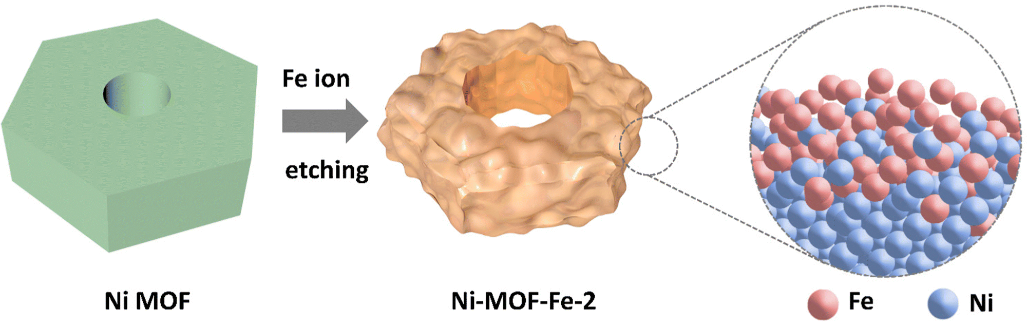 | ||
| Scheme 1 The fabrication of Ni-MOF-Fe-2. | ||
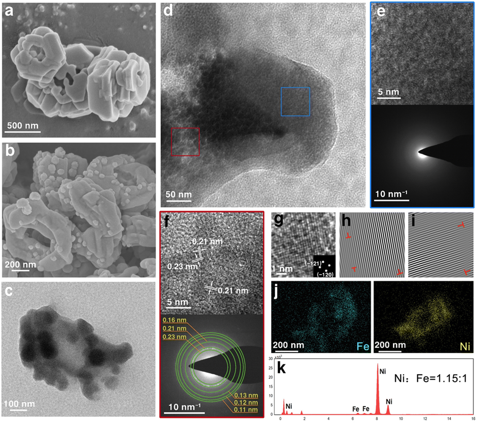 | ||
| Fig. 1 (a) SEM images of Ni MOF. (b) SEM, (c and d) TEM images of Ni-MOF-Fe-2. (e and f) High resolution TEM images and the corresponding SAED in (d). (g) Atomic lattice image in (f), inset: FFT pattern. (h) Atomic lattice image of (g) imaged along the (−121) lattice plane, and (i) atomic lattice image of (g) imaged along the (−120) lattice plane. (j) Elemental mapping of Fe and Ni in Ni-MOF-Fe-2. (k) EDX results of Ni-MOF-Fe-2. | ||
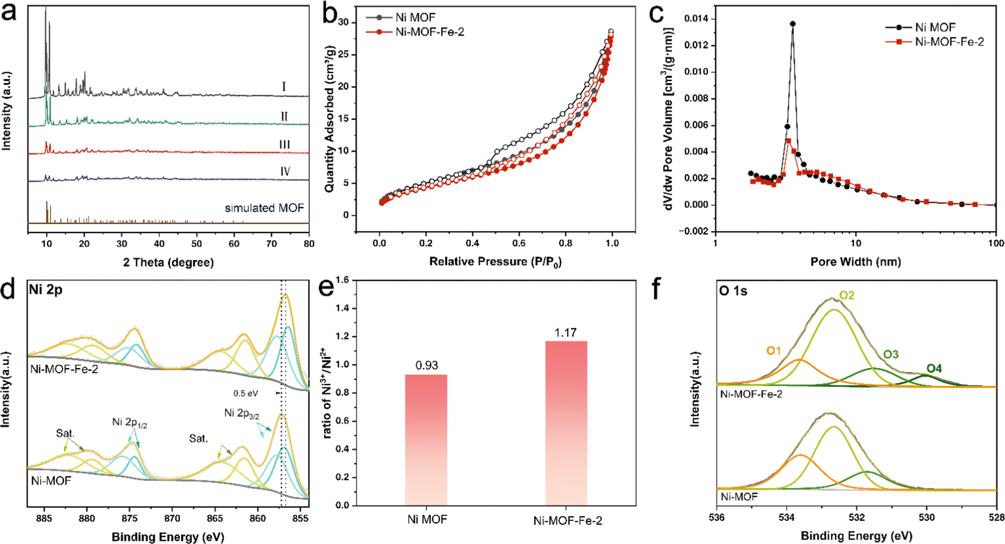 | ||
| Fig. 2 (a) XRD patterns tested and simulated, (b) N2 absorption-desorption isotherms, (c) pore width distribution, (d) high-resolution XPS spectra of Ni 2p, (e) ratio of Ni3+/Ni2+ and (f) high-resolution XPS spectra of O 1s of Ni MOF and Ni-MOF-Fe-2. | ||
To further investigate the process of the MOF material structure evolution, powder X-ray diffraction (PXRD) was applied to study the crystal structure. As shown in Fig. 2a, lines I, II, III, and IV belonged to Ni MOF, Ni-MOF-Fe-1, Ni-MOF-Fe-2, and Ni-MOF-Fe-3, respectively, and all the peaks of each sample were well fitted with [Ni3(HCOO)6]·DMF reported by Li et al.,41 which verified the successful synthesis of target MOF.
The difference was that the peak intensity of the samples after Fe ion etching got weaker and decreased with the increase of iron ion concentration. It suggested that the Fe ions could etch samples effectively and cause crystal amorphization, which formed defects in the crystal and, in turn, became the active sites during the reaction process.49
N2 absorption and desorption isotherms were employed to ascertain the specific surface area and pore size distribution of Ni MOF and Ni-MOF-Fe-2. In Fig. 2b and c, the two samples showed similar isotherms, suggesting that the specific surface area and pore structure of the products were well maintained under the action of suitable concentration of iron ions, and the measured specific surface areas of Ni MOF and Ni-MOF-Fe-2 were 19.1 and 16.2 m2 g−1, and their pore volumes were 0.042 and 0.041 cm3 g−1, respectively. The pore width distribution in Fig. 2c showed the pores in Ni MOF concentrated on 3.5 nm, which featured the common mesoporous MOF,50 while the pore width of Ni-MOF-Fe-2 got more emanative and the proportion of the pore width between 4–10 nm increased compared to Ni MOF (Fig. S7, ESI†). Therefore, the specific surface area and pore volume of Ni-MOF-Fe-2 were basically maintained after etching, and some larger pores were introduced, facilitating the exposure of active sites and mass transfer at the catalytic interface.
X-ray photoelectron spectroscopy was adopted to study the chemical states and electronic interactions of the main elements before and after Fe ion etching. Fig. S8 (ESI†) gave high-resolution XPS of C 1s of Ni MOF and Ni-MOF-Fe-2, which can be fitted to the peaks located at 284.8, 285.8, and 289.2 eV and assigned to C–C, C–N, and –COOH species, respectively.9,42 Ni 2p spectra in Fig. 2d showed the peaks centered at 856.7 and 857.6 eV arising from Ni2+ and Ni3+.39,51,52 After etching, the ratio of Ni3+/Ni2+ increased from 0.93 to 1.17 (Fig. 2e), indicating that strong electronic interactions occurred between Ni and Fe and higher chemical valence state nickel ions were produced, which was more favourable to boosting the OER catalytic activity.52,53 Moreover, the O 1s spectra were deconvoluted into peaks centered at 533.7(O1), 532.6(O2), and 531.3(O3) eV in Fig. 2f, which were caused by water molecules adsorbed on the surface, hydroxyl groups (–OH), and lattice oxygen.54,55 It is observed that a peak centered at 529.7 eV emerged in Ni-MOF-Fe-2, which can be assigned to the oxygen vacancy (Ov) resulting from the Fe doping treatment.56,57 Compared with Ni MOF, the spectrum of Ni 2p in Ni-MOF-Fe-2 showed a 0.5 eV negative shift, indicating that the electronic configuration of Ni has been modulated by the doped Fe, and strong electronic interaction occurred between the metal ions.58 Thus, more active sites were introduced and the OER performance was significantly enhanced.
The OER activity of the as-prepared catalysts was evaluated in 1.0 M KOH solution and benchmarked against that of bare Ni MOF and commercial IrO2 catalyst, and all the curves were collected without iR-correction. Encouraged by the introduction of Fe, Ni-MOF-Fe-2 exhibited an advanced OER performance. Fig. 3a and b show the evolution CV curves of Ni MOF and Ni-MOF-Fe-2, revealing the activation process of these two samples. Note that the intensity of the Ni2+/Ni3+ redox peak increased with the CV cycles and tends to be stable. Compared with the unchanged cathodic peak in Ni MOF catalyst, the cathodic peak of Ni-MOF-Fe-2 showed an evident negative shift (−39 mV) from the first scan to the 100th one, accompanied by the increased cut-off current density (Fig. S9, ESI†). The phenomenon originated from the introduction of iron ions, which regulated the local electronic environment of Ni, facilitating the catalyst more advantageous for the OER process,59–61 rather than simply through the transient current increase caused by the oxidation of nickel ions, which was unstable and descending. Therefore, the as-prepared Ni-MOF-Fe-2 possessed outstanding OER performances. As shown in Fig. 3c, the LSV curve of Ni-MOF-Fe-2 overwhelmed that of the precursor Ni MOF and commercial IrO2, demonstrating that the unique iron ion etching was highly favourable for the OER process, and this was supported by the Tafel slopes in Fig. 3d and comparison in Fig. 3e, where the Ni-MOF-Fe-2 can deliver a current density of 10 mA cm−2 with an overpotential of only 269 mV, outperforming that of commercial IrO2 (319 mV) and significantly exceeding bare Ni MOF (524 mV). Meanwhile, Ni-MOF-Fe-2 showed the largest current density of 25.15 mA cm−2 and 100.1 mA cm−2 at the overpotential of 300 mV and 400 mV, respectively, which were almost 4.9 times and 2.1 times that of IrO2, and even 79.6 times and 37.8 times that of Ni MOF under the same condition. The smallest Tafel slope of the target sample (47.1 mV dec−1 for Ni-MOF-Fe-2, 57.7 mV dec−1 for IrO2, 100.6 mV dec−1 for Ni MOF) verified its intrinsically enhanced catalytic activity and kinetics, illustrating the significant role of Fe ion etching in boosting OER performance. More than that, such Tafel slope and overpotential of Ni-MOF-Fe-2 were lower than most of the previously reported powder catalysts, as listed in Fig. 3f and Table S2 (ESI†). Furthermore, we found that the catalytic activities of the materials depended on the concentration of Fe ions. As shown in Fig. S10 (ESI†), the catalytic activity of the products exhibited a volcano-type variation as the concentration of iron ion etching increased. The precursor Ni MOF showed an obvious improvement in catalytic activities under the 0.01 M Fe ion etching effect (Ni-MOF-Fe-1, η10 = 294 mV, Tafel slope = 52.7 mV dec−1), and this positive promotion reached the maximum for Ni-MOF-Fe-2, subsequently showing a decreasing trend for Ni-MOF-Fe-3 (η10 = 294 mV, Tafel slope = 52.7 mV dec−1). Therefore, the Ni-MOF-Fe-2 was synthesized with the optimal Fe ion concentration of 0.02 M.
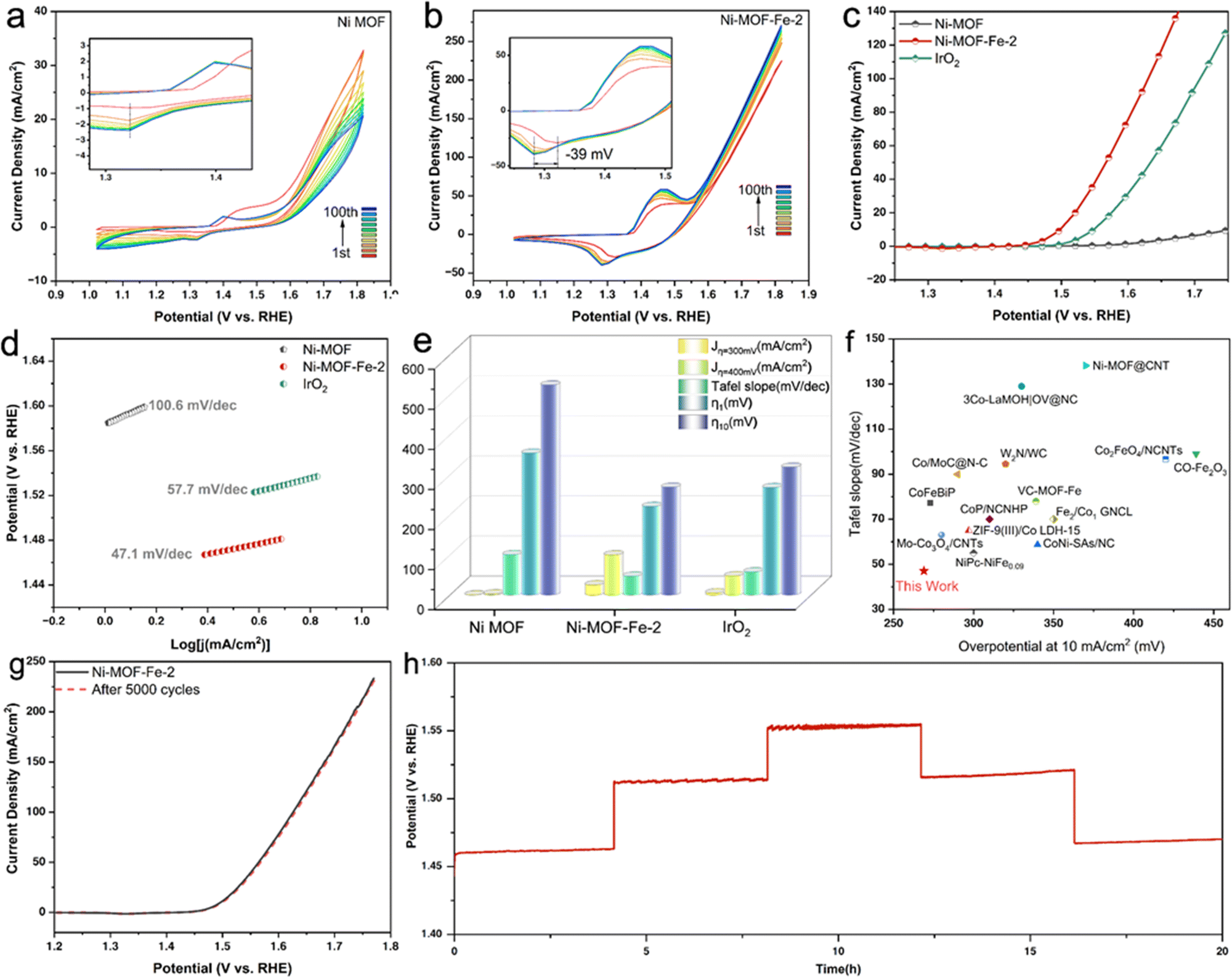 | ||
| Fig. 3 OER performances. The evolution of CV curves for (a) Ni MOF and (b) Ni-MOF-Fe-2 from the 1st to the 300th scan at 500 mV s−1, inset: enlarged curves of redox peaks at around 1.3 V (vs. RHE). (c) LSV OER polarization curves of the catalysts without iR-correction. (d) Corresponding Tafel slopes in (c). (e) Comparison of overpotentials at 1 mA cm−2 (η1) and 10 mA cm−2 (η10), the current densities under overpotentials of 300 mV and 400 mV, and the Tafel slopes obtained from the catalysts. (f) The OER activity comparison from the literature showing the overpotential at 10 mA cm−2 with Tafel slope. (g) Polarization curves of Ni-MOF-Fe-2 at the 1st and 5000th cycle for OER. (h) Chronopotentiometric curve of Ni-MOF-Fe-2 at 5 mA cm−2, 20 mA cm−2, and 40 mA cm−2. | ||
Additionally, long-term durability is another important criterion for assessing large-scale applications for catalysts. To this end, successive CV scanning tests with a fast speed of 500 mV s−1 were exerted on Ni-MOF-Fe-2, and the LSV curve after 5000 cycles overlapped with the initial one (Fig. 3g), demonstrating its outstanding durability. Moreover, the multipotential process and long-term stability response of the material were tested. The results in Fig. 3h showed a rapid and recoverable potential response at different current densities, demonstrating the as-prepared sample featured robust mechanical stabilities and excellent electrical conductivity. Fig. S11 (ESI†) shows the result of a 30 h chronopotentiometry test, which confirmed the outstanding catalytic stability of Ni-MOF-Fe-2.
To get a deeper insight into possible reasons for the remarkable OER performance of Ni-MOF-Fe-2, data from electrochemical impedance spectroscopy (EIS) were further collected and studied. According to previous reports, EIS is a potential method to investigate the dynamics of electrocatalytic reactions and the behavior of the electrode/electrolyte boundary.49,62 Therefore, Operando EIS measurements of these synthesized catalysts were carried out. As shown in Fig. 4a, Nyquist plots of the 4 samples exhibited semi-circles with different diameters. Among them, Ni-MOF-Fe-2 possessed the smallest semi-circle, illustrating its fastest electron transfer efficiency. The fitting results in Fig. S12 and Table S3 (ESI†) revealed that the charge transfer resistances (Rct) of these catalysts were 460.23 Ω (Ni MOF), 60.14 Ω (Ni-MOF-Fe-1), 8.31 Ω (Ni-MOF-Fe-2), and 33.39 Ω (Ni-MOF-Fe-3), indicating Fe ion etching can significantly decrease Rct and improve the electrical conductivity of catalysts. In addition, Bode plots of Ni MOF and Ni-MOF-Fe-2 at different applied potentials (from 1.495 V to 1.595 V vs. RHE) were conducted to simulate Operando EIS tests, as shown in Fig. 4b and c, and the peak shifted to the high-frequency region with the increasing potential, and this process occurred in the lower frequency region for Ni-MOF-Fe-2, which was related to faster deprotonation of the *OOH intermediate.63,64 In Fig. 4d, the phase angle of Ni-MOF-Fe-2 was much smaller than that of Ni-MOF at each potential, indicating more electrons participate in the OER process.65 This conclusion was validated by the Operando EIS tests of different Fe ion concentrations (Fig. S13, ESI†) again. Moreover, we estimated the electrochemical surface area (ECSA) by measuring the double-layer capacitance (Cdl) of the catalysts. Fig. S14 (ESI†) showed the Cdl valve of Ni-MOF-Fe-2 was the largest one, demonstrating that the optimal etching concentration yielded the maximum active area and the most active sites for the catalyst, which is well consistent with the OER performance and EIS results described previously.39
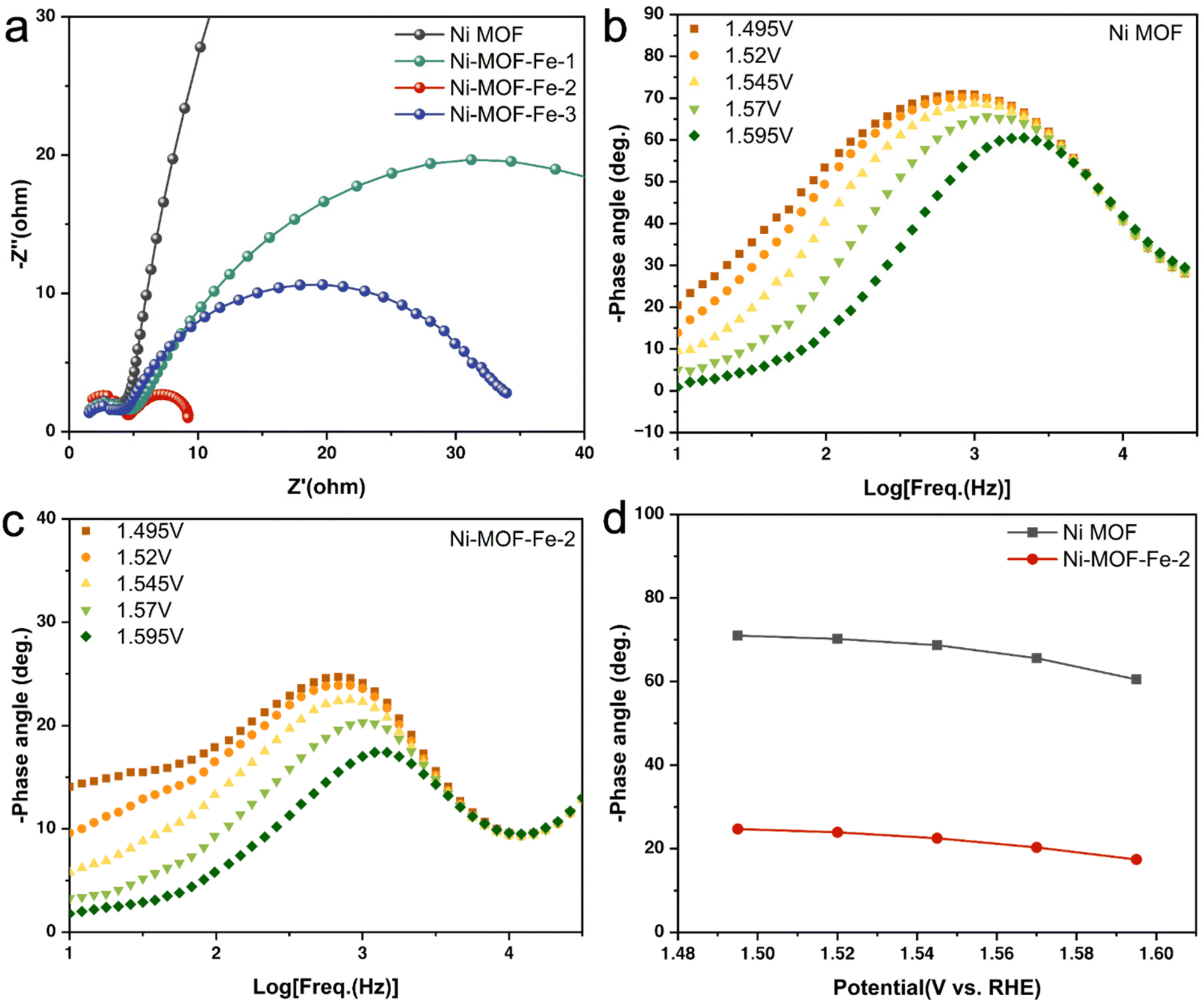 | ||
| Fig. 4 (a) Nyquist plots of the catalysts at the potential of 1.52 V (vs. RHE). Bode plots of (b) Ni MOF and (c) Ni-MOF-Fe-2 obtained under different potentials. (d) Potential dependence of the phase angle of Ni MOF and Ni-MOF-Fe-2. | ||
Finally, characterization of post-testing Ni-MOF-Fe-2 was conducted. SEM images in Fig. S15 (ESI†) showed the post-test sample retained the bulk structure, and its surface got rougher with few spherical amorphous structures left, which may be caused by the surface reconstruction during the OER activation process.61 XRD pattern in Fig. S16 (ESI†) indicated the etched MOF was transformed to nickel oxyhydroxide (PDF#22-0444), which was reasonable in alkaline solution. XPS results in Fig. S17 and S18 (ESI†) showed that the ratio of Ni3+/Ni2+ increased after OER, which was caused by the formation of NiOOH.66,67 Additionally, the lattice oxygen centered at about 531 eV evidently increased, confirming the proliferated oxyhydroxide, and it is regarded as the active species in many research works.68,69
Conclusions
In this paper, we designed Fe ion etched nickel-based MOF catalysts to explore their OER performances. As a result, the most outstanding Ni-MOF-Fe-2 reached an overpotential of 269 mV at 10 mA cm−2 with a small Tafel slope of 47.1 mV dec−1, and it exhibited pretty good durability of 5000 cycles CV test and 30 h chronopotentiometry test. We found that appropriate Fe ion etching modulated the crystallinity and pore structure, and most importantly, the guest element doping formed many dislocations and stacking faults between the lattice planes, becoming active sites and accelerating the kinetics during the OER process. The Ni-MOF-Fe-2 outperformed IrO2 and inspired a rational design of advanced catalysts. The etching method toward Ni MOFs in this work and thus harvesting their advanced electrochemical performances may create a new path for fabricating other excellent MOF-based catalysts.Conflicts of interest
There are no conflicts to declare.Acknowledgements
This work was financially supported by the Natural Science Foundation of Hubei Province (2021CFB144), the Fundamental Research Funds for the Central Universities (2042021kf0077), as well as the Large-scale Instrument and Equipment Sharing Foundation of Wuhan University.Notes and references
- K. Zeng, X. J. Zheng, C. Li, J. Yan, J. H. Tian, C. Jin, P. Strasser and R. Z. Yang, Recent Advances in Non-Noble Bifunctional Oxygen Electrocatalysts toward Large-Scale Production, Adv. Funct. Mater., 2020, 30, 2000503 CrossRef CAS.
- N. Kannan and D. Vakeesan, Solar energy for future world: - A review, Renew. Sust. Energ. Rev, 2016, 62, 1092–1105 CrossRef.
- T. Abbasi and S. A. Abbasi, 'Renewable' hydrogen: Prospects and challenges, Renew. Sust. Energ. Rev, 2011, 15, 3034–3040 CrossRef.
- F. Zhang, P. C. Zhao, M. Niu and J. Maddy, The survey of key technologies in hydrogen energy storage, Int. J. Hydrogen Energy, 2016, 41, 14535–14552 CrossRef CAS.
- M. S. Islam, M. Kim, X. Y. Jin, S. M. Oh, N. S. Lee, H. Kim and S. J. Hwang, Bifunctional 2D Superlattice Electrocatalysts of Layered Double Hydroxide-Transition Metal Dichalcogenide Active for Overall Water Splitting, ACS Energy Lett., 2018, 3, 952–960 CrossRef CAS.
- J. Zhang, Q. Zhang and X. Feng, Support and Interface Effects in Water-Splitting Electrocatalysts, Adv. Mater., 2019, 31, 1808167 CrossRef PubMed.
- Y. J. Li, Y. J. Sun, Y. N. Qin, W. Y. Zhang, L. Wang, M. C. Luo, H. Yang and S. J. Guo, Recent Advances on Water-Splitting Electrocatalysis Mediated by Noble-Metal-Based Nanostructured Materials, Adv. Energy Mater., 2020, 10, 1903120 CrossRef CAS.
- X. Li, L. Xiao, L. Zhou, Q. Xu, J. Weng, J. Xu and B. Liu, Adaptive Bifunctional Electrocatalyst of Amorphous CoFe Oxide @ 2D Black Phosphorus for Overall Water Splitting, Angew. Chem., Int. Ed., 2020, 59, 21106–21113 CrossRef CAS PubMed.
- H. Sun, Y. Lian, C. Yang, L. Xiong, P. Qi, Q. Mu, X. Zhao, J. Guo, Z. Deng and Y. Peng, A hierarchical nickel–carbon structure templated by metal–organic frameworks for efficient overall water splitting, Energy Environ. Sci., 2018, 11, 2363–2371 RSC.
- J. J. Song, C. Wei, Z. F. Huang, C. T. Liu, L. Zeng, X. Wang and Z. C. J. Xu, A review on fundamentals for designing oxygen evolution electrocatalysts, Chem. Soc. Rev., 2020, 49, 2196–2214 RSC.
- K. H. Yue, J. L. Liu, C. F. Xia, K. Zhan, P. Wang, X. Y. Wang, Y. Yan and B. Y. Xia, Controllable synthesis of multidimensional carboxylic acid-based NiFe MOFs as efficient electrocatalysts for oxygen evolution, Mater. Chem. Front., 2021, 5, 7191–7198 RSC.
- J. Li and S. Gadipelli, Synthesis and Optimization of Zeolitic Imidazolate Frameworks for the Oxygen Evolution Reaction, Chem. – Eur. J., 2020, 26, 14167–14172 CrossRef CAS PubMed.
- Z. P. Wu, X. F. Lu, S. Q. Zang and X. W. Lou, Non-Noble-Metal-Based Electrocatalysts toward the Oxygen Evolution Reaction, Adv. Funct. Mater., 2020, 30, 1910274 CrossRef CAS.
- M. Asnavandi and C. Zhao, Autologous growth of nickel oxyhydroxides with in situ electrochemical iron doping for efficient oxygen evolution reactions, Mater. Chem. Front., 2017, 1, 2541–2546 RSC.
- S. Yuan, L. Feng, K. C. Wang, J. D. Pang, M. Bosch, C. Lollar, Y. J. Sun, J. S. Qin, X. Y. Yang, P. Zhang, Q. Wang, L. F. Zou, Y. M. Zhang, L. L. Zhang, Y. Fang, J. L. Li and H. C. Zhou, Stable Metal-Organic Frameworks: Design, Synthesis, and Applications, Adv. Mater., 2018, 30, 1704303 CrossRef PubMed.
- C. C. Hou, L. L. Zou, Y. Wang and Q. Xu, MOF-Mediated Fabrication of a Porous 3D Superstructure of Carbon Nanosheets Decorated with Ultrafine Cobalt Phosphide Nanoparticles for Efficient Electrocatalysis and Zinc-Air Batteries, Angew. Chem., Int. Ed., 2020, 59, 21360–21366 CrossRef CAS PubMed.
- E. Ploetz, H. Engelke, U. Lächelt and S. Wuttke, The Chemistry of Reticular Framework Nanoparticles: MOF, ZIF, and COF Materials, Adv. Funct. Mater., 2020, 30, 1909062 CrossRef CAS.
- P. Valvekens, F. Vermoortele and D. De Vos, Metal-organic frameworks as catalysts: the role of metal active sites, Catal. Sci. Technol., 2013, 3, 1435–1445 RSC.
- P. Q. Liao, J. Q. Shen and J. P. Zhang, Metal-organic frameworks for electrocatalysis, Coord. Chem. Rev., 2018, 373, 22–48 CrossRef CAS.
- X. B. Liu, T. Yue, K. Qi, Y. B. Qiu, B. Y. Xia and X. P. Guo, Metal-organic framework membranes: From synthesis to electrocatalytic applications, Chin. Chem. Lett., 2020, 31, 2189–2201 CrossRef CAS.
- X. Duan, N. Pan, C. Sun, K. Zhang, X. Zhu, M. Zhang, L. Song and H. Zheng, MOF-derived Co-MOF,O-doped carbon as trifunctional electrocatalysts to enable highly efficient Zn–air batteries and water-splitting, J. Energy Chem., 2021, 56, 290–298 CrossRef.
- Y. Guo, J. Tang, Z. Wang, Y.-M. Kang, Y. Bando and Y. Yamauchi, Elaborately assembled core-shell structured metal sulfides as a bifunctional catalyst for highly efficient electrochemical overall water splitting, Nano Energy, 2018, 47, 494–502 CrossRef CAS.
- C. Hu, H. Jin, B. Liu, L. Liang, Z. Wang, D. Chen, D. He and S. Mu, Propagating Fe-N4 active sites with Vitamin C to efficiently drive oxygen electrocatalysis, Nano Energy, 2021, 82, 105714 CrossRef CAS.
- H. Yan, Y. Xie, A. Wu, Z. Cai, L. Wang, C. Tian, X. Zhang and H. Fu, Anion-Modulated HER and OER Activities of 3D Ni-V-Based Interstitial Compound Heterojunctions for High-Efficiency and Stable Overall Water Splitting, Adv. Mater., 2019, 31, e1901174 CrossRef PubMed.
- Y. D. Pan, R. Abazari, Y. H. Wu, J. K. Gao and Q. C. Zhang, Advances in metal-organic frameworks and their derivatives for diverse electrocatalytic applications, Electrochem. Commun., 2021, 126, 107024 CrossRef CAS.
- C. Feng, M. B. Faheem, J. Fu, Y. Q. Xiao, C. L. Li and Y. B. Li, Fe-Based Electrocatalysts for Oxygen Evolution Reaction: Progress and Perspectives, ACS Catal., 2020, 10, 4019–4047 CrossRef CAS.
- X. Long, H. Lin, D. Zhou, Y. An and S. Yang, Enhancing Full Water-Splitting Performance of Transition Metal Bifunctional Electrocatalysts in Alkaline Solutions by Tailoring CeO2–Transition Metal Oxides–Ni Nanointerfaces, ACS Energy Lett., 2018, 3, 290–296 CrossRef CAS.
- Y. W. Li, T. Zhao, M. T. Lu, Y. H. Wu, Y. B. Xie, H. Xu, J. K. Gao, J. M. Yao, G. D. Qian and Q. C. Zhang, Enhancing Oxygen Evolution Reaction through Modulating Electronic Structure of Trimetallic Electrocatalysts Derived from Metal-Organic Frameworks, Small, 2019, 15, 1901940 CrossRef CAS PubMed.
- Q. X. Mou, Z. H. Xu, G. N. Wang, E. L. Li, J. Y. Liu, P. P. Zhao, X. H. Liu, H. B. Li and G. Z. Cheng, A bimetal hierarchical layer structure MOF grown on Ni foam as a bifunctional catalyst for the OER and HER, Inorg. Chem. Front., 2021, 8, 2889–2899 RSC.
- T. V. M. Sreekanth, G. R. Dillip, P. C. Nagajyothi, K. Yoo and J. Kim, Integration of Marigold 3D flower-like Ni-MOF self-assembled on MWCNTs via microwave irradiation for high-performance electrocatalytic alcohol oxidation and oxygen evolution reactions, Appl. Catal. B-Environ., 2021, 285, 119793 CrossRef CAS.
- S. Zhu, Q. Meng, L. Wang, J. Zhang, Y. Song, H. Jin, K. Zhang, H. Sun, H. Wang and B. Yang, Highly photoluminescent carbon dots for multicolor patterning, sensors, and bioimaging, Angew. Chem., Int. Ed., 2013, 52, 3953–3957 CrossRef CAS PubMed.
- Q. X. Mou, X. Wang, Z. H. Xu, P. Zul, E. L. Li, P. P. Zhao, X. H. Liu, H. B. Li and G. Z. Cheng, A synergy establishment by metal-organic framework and carbon quantum dots to enhance electrochemical water oxidation, Chin. Chem. Lett., 2022, 33, 562–566 CrossRef CAS.
- H. Zhou, T. Yang, Z. K. Kou, L. Shen, Y. F. Zhao, Z. Y. Wang, X. Q. Wang, Z. K. Yang, J. Y. Du, J. Xu, M. Chen, L. Tian, W. X. Guo, Q. P. Wang, H. W. Lv, W. X. Chen, X. Hong, J. Luo, D. P. He and Y. E. Wu, Negative Pressure Pyrolysis Induced Highly Accessible Single Sites Dispersed on 3D Graphene Frameworks for Enhanced Oxygen Reduction, Angew. Chem., Int. Ed., 2020, 59, 20465–20469 CrossRef CAS PubMed.
- Y. Wang, B. Liu, X. Shen, H. Arandiyan, T. Zhao, Y. Li, M. Garbrecht, Z. Su, L. Han, A. Tricoli and C. Zhao, Engineering the Activity and Stability of MOF-Nanocomposites for Efficient Water Oxidation, Adv. Energy Mater., 2021, 11, 2003759 CrossRef CAS.
- X. Wei, N. Liu, W. Chen, S. Qiao and Y. Chen, Three-phase composites of NiFe2O4/Ni@C nanoparticles derived from metal-organic frameworks as electrocatalysts for the oxygen evolution reaction, Nanotechnology, 2021, 32, 175701 CrossRef PubMed.
- Y. Zhou, Z. Wang, Z. Pan, L. Liu, J. Xi, X. Luo and Y. Shen, Exceptional Performance of Hierarchical Ni-Fe (hydr)oxide@NiCu Electrocatalysts for Water Splitting, Adv. Mater., 2019, 31, e1806769 CrossRef PubMed.
- Y. Zhang, Z. Y. Zeng and D. R. Ho, Mn dopant induced high-valence Ni(3 +)sites and oxygen vacancies for enhanced water oxidation, Mater. Chem. Front., 2020, 4, 1993–1999 RSC.
- S. Anantharaj, S. Kundu and S. Noda, “The Fe Effect”: A review unveiling the critical roles of Fe in enhancing OER activity of Ni and Co based catalysts, Nano Energy, 2021, 80, 105514 CrossRef CAS.
- C. Huang, Y. Zhong, J. Chen, J. Li, W. Zhang, J. Zhou, Y. Zhang, L. Yu and Y. Yu, Fe induced nanostructure reorganization and electronic structure modulation over CoNi (oxy)hydroxide nanorod arrays for boosting oxygen evolution reaction, Chem. Eng. J., 2021, 403, 126304 CrossRef CAS.
- Y. W. Li, M. T. Lu, Y. H. Wu, Q. H. Ji, H. Xu, J. K. Gao, G. D. Qian and Q. C. Zhang, Morphology regulation of metal-organic framework-derived nanostructures for efficient oxygen evolution electrocatalysis, J. Mater. Chem. A, 2020, 8, 18215–18219 RSC.
- K. H. Li, D. H. Olsan, J. Y. Lee, W. H. Bi, K. Wu, T. Yuen, Q. Xu and J. Li, Multifunctional microporous MOFs exhibiting gas/hydrocarbon adsorption selectivity, separation capability and three-dimensional magnetic ordering, Adv. Funct. Mater., 2008, 18, 2205–2214 CrossRef CAS.
- C. Wang, H. Yang, Y. Zhang and Q. Wang, NiFe Alloy Nanoparticles with hcp Crystal Structure Stimulate Superior Oxygen Evolution Reaction Electrocatalytic Activity, Angew. Chem., Int. Ed., 2019, 58, 6099–6103 CrossRef CAS PubMed.
- K. Huang, D. Peng, Z. Yao, J. Xia, B. Zhang, H. Liu, Z. Chen, F. Wu, J. Wu and Y. Huang, Cathodic plasma driven self-assembly of HEAs dendrites by pure single FCC FeCoNiMnCu nanoparticles as high efficient electrocatalysts for OER, Chem. Eng. J., 2021, 425, 131533 CrossRef CAS.
- K. Huang, B. Zhang, J. Wu, T. Zhang, D. Peng, X. Cao, Z. Zhang, Z. Li and Y. Huang, Exploring the impact of atomic lattice deformation on oxygen evolution reactions based on a sub-5 nm pure face-centred cubic high-entropy alloy electrocatalyst, J. Mater. Chem. A, 2020, 8, 11938–11947 RSC.
- M. Kuang, J. Zhang, D. Liu, H. Tan, K. N. Dinh, L. Yang, H. Ren, W. Huang, W. Fang, J. Yao, X. Hao, J. Xu, C. Liu, L. Song, B. Liu and Q. Yan, Amorphous/Crystalline Heterostructured Cobalt-Vanadium-Iron (Oxy)hydroxides for Highly Efficient Oxygen Evolution Reaction, Adv. Energy Mater., 2020, 10, 2002215 CrossRef CAS.
- H. Liang, A. N. Gandi, C. Xia, M. N. Hedhili, D. H. Anjum, U. Schwingenschlögl and H. N. Alshareef, Amorphous NiFe-OH/NiFeP Electrocatalyst Fabricated at Low Temperature for Water Oxidation Applications, ACS Energy Lett., 2017, 2, 1035–1042 CrossRef CAS.
- D. T. Harvey and R. W. Linton, Chemical characterization of hydrous ferric oxides by x-ray photoelectron spectroscopy, Anal. Chem., 2002, 53, 1684–1688 CrossRef.
- M. Oku, K. Wagatsuma and T. Konishi, Relation between 2p X-ray photoelectron and K alpha X-ray emission spectra of manganese and iron oxides, J. Electron Spectrosc. Relat. Phenom., 1999, 98, 277–285 CrossRef.
- Z. Xiao, Y. C. Huang, C. L. Dong, C. Xie, Z. Liu, S. Du, W. Chen, D. Yan, L. Tao, Z. Shu, G. Zhang, H. Duan, Y. Wang, Y. Zou, R. Chen and S. Wang, Operando Identification of the Dynamic Behavior of Oxygen Vacancy-Rich Co3O4 for Oxygen Evolution Reaction, J. Am. Chem. Soc., 2020, 142, 12087–12095 CrossRef CAS PubMed.
- Z. Zhang, Y. Du, Q. C. Wang, J. Xu, Y. N. Zhou, J. Bao, J. Shen and X. Zhou, A Yolk-Shell-Structured FePO4 Cathode for High-Rate and Long-Cycling Sodium-Ion Batteries, Angew. Chem., Int. Ed., 2020, 59, 17504–17510 CrossRef CAS PubMed.
- K. Wan, J. Luo, C. Zhou, T. Zhang, J. Arbiol, X. Lu, B. W. Mao, X. Zhang and J. Fransaer, Hierarchical Porous Ni3S4 with Enriched High-Valence Ni Sites as a Robust Electrocatalyst for Efficient Oxygen Evolution Reaction, Adv. Funct. Mater., 2019, 29, 1900315 CrossRef.
- Z. Chen, B. Zhao, Y. C. He, H. R. Wen, X. Z. Fu, R. Sun and C. P. Wong, NiCo2O4 nanoframes with a nanosheet surface as efficient electrocatalysts for the oxygen evolution reaction, Mater. Chem. Front., 2018, 2, 1155–1164 RSC.
- X. Du, Z. Yang, Y. Li, Y. Gong and M. Zhao, Controlled synthesis of Ni(OH)2/Ni3S2 hybrid nanosheet arrays as highly active and stable electrocatalysts for water splitting, J. Mater. Chem. A, 2018, 6, 6938–6946 RSC.
- X. Han, X. Ling, D. Yu, D. Xie, L. Li, S. Peng, C. Zhong, N. Zhao, Y. Deng and W. Hu, Atomically Dispersed Binary Co-Ni Sites in Nitrogen-Doped Hollow Carbon Nanocubes for Reversible Oxygen Reduction and Evolution, Adv. Mater., 2019, 31, 1905622 CrossRef CAS PubMed.
- Z. Wang, S. Zeng, W. Liu, X. Wang, Q. Li, Z. Zhao and F. Geng, Coupling Molecularly Ultrathin Sheets of NiFe-Layered Double Hydroxide on NiCo2O4 Nanowire Arrays for Highly Efficient Overall Water-Splitting Activity, ACS Appl. Mater. Interfaces, 2017, 9, 1488–1495 CrossRef CAS PubMed.
- C. Liu, J. Wang, J. Wan, Y. Cheng, R. Huang, C. Zhang, W. Hu, G. Wei and C. Yu, Amorphous Metal-Organic Framework-Dominated Nanocomposites with Both Compositional and Structural Heterogeneity for Oxygen Evolution, Angew. Chem., Int. Ed., 2020, 59, 3630–3637 CrossRef CAS PubMed.
- Y. Wu, Y. Li, J. Gao and Q. Zhang, Recent advances in vacancy engineering of metal-organic frameworks and their derivatives for electrocatalysis, SusMat, 2021, 1, 66–87 CrossRef.
- Q. Liu, J. Huang, X. Zhang, L. Cao, D. Yang, J.-H. Kim and L. Feng, Controllable Conversion from Single-Crystal Nanorods to Polycrystalline Nanosheets of NiCoV-LTH for Oxygen Evolution Reaction at Large Current Density, ACS Sustainable Chem. Eng., 2020, 8, 16091–16096 CrossRef CAS.
- A. Balram, H. F. Zhang and S. Santhanagopalan, In situ decoration of stainless steel nanoparticles for synergistic enhancement of alpha-Ni(OH)(2) oxygen evolution reaction catalysis, Mater. Chem. Front., 2017, 1, 2376–2382 RSC.
- J. D. Chen, F. Zheng, S. J. Zhang, A. Fisher, Y. Zhou, Z. Y. Wang, Y. Y. Li, B. B. Xu, J. T. Li and S. G. Sun, Interfacial Interaction between FeOOH and Ni-Fe LDH to Modulate the Local Electronic Structure for Enhanced OER Electrocatalysis, ACS Catal., 2018, 8, 11342–11351 CrossRef CAS.
- S. Li, Z. Li, R. Ma, C. Gao, L. Liu, L. Hu, J. Zhu, T. Sun, Y. Tang, D. Liu and J. Wang, A Glass-Ceramic with Accelerated Surface Reconstruction toward the Efficient Oxygen Evolution Reaction, Angew. Chem., Int. Ed., 2021, 60, 3773–3780 CrossRef CAS PubMed.
- M. E. G. Lyons and M. P. Brandon, The significance of electrochemical impedance spectra recorded during active oxygen evolution for oxide covered Ni, Co and Fe electrodes in alkaline solution, J. Electroanal. Chem., 2009, 631, 62–70 CrossRef CAS.
- S. Watzele and A. S. Bandarenka, Quick Determination of Electroactive Surface Area of Some Oxide Electrode Materials, Electroanalysis, 2016, 28, 2394–2399 CrossRef CAS.
- C. S. Hsu, N. T. Suen, Y. Y. Hsu, H. Y. Lin, C. W. Tung, Y. F. Liao, T. S. Chan, H. S. Sheu, S. Y. Chen and H. M. Chen, Valence- and element-dependent water oxidation behaviors: in situ X-ray diffraction, absorption and electrochemical impedance spectroscopies, Phys. Chem. Chem. Phys., 2017, 19, 8681–8693 RSC.
- T. W. Zhao, X. J. Shen, Y. Wang, R. K. Hocking, Y. B. Li, C. L. Rong, K. Dastafkan, Z. Su and C. Zhao, In Situ Reconstruction of V-Doped Ni2P Pre-Catalysts with Tunable Electronic Structures for Water Oxidation, Adv. Funct. Mater., 2021, 31, 2100614 CrossRef CAS.
- Q. Qian, Y. Li, Y. Liu, L. Yu and G. Zhang, Ambient Fast Synthesis and Active Sites Deciphering of Hierarchical Foam-Like Trimetal-Organic Framework Nanostructures as a Platform for Highly Efficient Oxygen Evolution Electrocatalysis, Adv. Mater., 2019, 31, 1901139 CrossRef PubMed.
- L. Trotochaud, S. L. Young, J. K. Ranney and S. W. Boettcher, Nickel-iron oxyhydroxide oxygen-evolution electrocatalysts: the role of intentional and incidental iron incorporation, J. Am. Chem. Soc., 2014, 136, 6744–6753 CrossRef CAS PubMed.
- X. T. Wang, T. Ouyang, L. Wang, J. H. Zhong, T. Ma and Z. Q. Liu, Redox-Inert Fe(3 +) Ions in Octahedral Sites of Co-Fe Spinel Oxides with Enhanced Oxygen Catalytic Activity for Rechargeable Zinc-Air Batteries, Angew. Chem., Int. Ed., 2019, 58, 13291–13296 CrossRef CAS PubMed.
- J. Qi, Y. P. Lin, D. Chen, T. Zhou, W. Zhang and R. Cao, Autologous Cobalt Phosphates with Modulated Coordination Sites for Electrocatalytic Water Oxidation, Angew. Chem., Int. Ed., 2020, 59, 8917–8921 CrossRef CAS PubMed.
Footnote |
| † Electronic supplementary information (ESI) available. See DOI: https://doi.org/10.1039/d2qm00388k |
| This journal is © the Partner Organisations 2022 |