DOI:
10.1039/D2QI00977C
(Research Article)
Inorg. Chem. Front., 2022,
9, 4244-4271
A review of recent developments for the in situ/operando characterization of nanoporous materials
Received
4th May 2022
, Accepted 16th June 2022
First published on 21st June 2022
Abstract
This is a review on up-to-date in situ/operando methods for a comprehensive characterization of nanoporous materials. The group of nanoporous materials is constantly growing, and with it, the variety of possible applications. Nanoporous materials include, among others, porous carbon materials, mesoporous silica, mesoporous transition metal oxides, zeolites, metal–organic frameworks (MOFs), or polymers. They are used as adsorbents, for gas storage, as catalysts, or for electrochemical applications to name just a few technical applications. Characterization of these materials has evolved from pure ex situ examination to increasingly complex in situ or operando methods. Monitoring nanoporous materials under reaction conditions allows for establishing structure–property relationships. This enables nanoporous materials to be adapted and optimized for specific processes. Recent developments on well-established but also exciting emerging methods for future applications will be discussed. The examples include in situ powder diffraction, total and small angle scattering, environmental electron microscopy, coupled with focused ion beam cutting, or X-ray tomography. This article will provide a useful reference to practitioners for in situ/operando characterization of nanoporous materials.
Introduction
The group of nanoporous materials comprises a large number of different materials with an equally wide variety of applications. According to IUPAC, porous materials can be classified into three groups: (a) microporous materials (0–2 nm pores), (b) mesoporous materials (2–50 nm pores), (c) macroporous materials (>50 nm pores).1,2 Nanoporous materials are a subset of porous materials, typically having large porosities, and pore diameters between 1–100 nm. However, the term nanoporous is sometimes also extended to materials with larger pore sizes up to 1000 nm.3 The material spectrum covers carbon materials (activated carbon or carbon nanotubes), polymers, zeolites and zeotypes, metal–organic frameworks, or mesoporous materials such as silicas, carbons, or metal oxides. High surface areas and defined pore structures make these materials suitable for many different applications.3,4 Zeolites for example are used for industrial catalytic processes, as ion exchangers,5 or mesoporous materials gained attraction for electrochemical energy conversion and storage.6 Nowadays, the characterization of materials can be performed on different length scales, ranging from atomic arrangements in solids and molecules up to macroscopic objects in the millimetre or centimetre range. For characterizing short-range features, local structures, such as coordination polyhedra or molecular entities, numerous spectroscopy techniques are available, including solid-state nuclear resonance (NMR) spectroscopy, Raman spectroscopy, UV-vis and/or IR spectroscopy or X-ray absorption methods, to name just a few. Diffraction techniques are used to study crystalline materials with 3-dimensionally ordered crystal structures. Complementary to that, scattering methods such as total scattering or small angle scattering (SAS) can be applied. Evaluation of total scattering data provides information on atomic structures on a more local length scale. Atom-atom distances in gases, liquids, and solids can be analyzed without requiring any ordering or periodicity. Small angle scattering provides information on the properties and arrangement of objects at the nanoscopic level. Imaging techniques complete the spectrum of methods providing information from the atomic level via transmission electron microscopy (TEM) or scanning transmission electron microscopy (STEM) up to the nanoscale using X-ray tomography. Some of these methods such as SAS are also excellent tools for the characterization of porous materials and are complementary to conventional gas adsorption (which will not be discussed in this review) or high resolution transmission electron microscopy (HR-TEM) as an imaging technique. There are many more techniques available for the characterization of nanoporous materials, namely, gas adsorption, porosimetry, or atomic force microscopy (AFM) which cannot be discussed in this review article. Neutron diffraction is used in crystal structure analysis to differentiate between next-neighbour elements in the periodic table for example Al and Si. While both elements cannot be distinguished by conventional X-ray diffraction experiments their scattering properties in the case of neutron diffraction are significantly different. Furthermore, adsorption from the gas phase into nanoporous materials can be followed by in situ temperature- and pressure-dependent neutron scattering experiments.7 The mobility of molecules can be monitored by quasielastic neutron scattering (QENS). One example is the in situ investigation of the dynamics of propane in nanoporous silica aerogel.8In situ methods for the characterization of nanoporous materials have undergone an incredible development over the last 1–2 decades. Understanding the crystallization and growth of nanoporous materials is still one of the most challenging issues in materials science. The development of in situ NMR techniques was one of the key inventions to follow crystallization on a local scale.9 Intensive developments have been also achieved in the combination of small angle scattering techniques with adsorption studies on metal–organic frameworks (MOFs), porous carbon materials, or zeolites. Following a catalytic reaction not only qualitatively but monitoring it on a structural level during the reaction was impossible for a very long time. Nowadays, exciting studies show the great potential of respective in situ (analysis of materials under non-ambient or reaction conditions) or operando (simultaneous analysis of structure and performance) methods. In situ and/or operando diffraction, scattering, or spectroscopy studies can be performed under variable temperature, stress, humidity, pressure, electrical potential, or reactant concentrations.
In this review, we will focus on recent technical and scientific developments for in situ characterization of nanoporous materials. The field of in situ/operando studies is very broad and it is far beyond the scope of this review to give a comprehensive summary of all potential methods and experiments. Next to well-established characterization methods, we will also highlight some techniques, which are not as frequently used, and we will discuss methods that have a great potential for future applications.
X-ray powder diffraction (XRPD)
Besides electron microscopy (EM), X-ray diffraction techniques (single-crystal and powder diffraction) are the most common characterization methods to study the crystal structure of nanoporous materials. Both single-crystal X-ray diffraction (SC-XRD) and X-ray powder diffraction (XRPD) are non-destructive techniques for exploring the long-range order of crystal structure providing information not only on crystal structures but also on phase compositions and microstructure of a given phase (space groups and lattice parameters, crystallite size, microstrain). Most porous materials such as MOFs, covalent organic frameworks (COFs), and particularly zeolites are synthesized as polycrystalline powders preventing the structure determination via SC-XRD.10–14 Therefore, the majority of structural investigations are carried out via XRPD. The reduction of the diffraction data to 1D diffraction patterns in XRPD, together with strongly overlapping reflections, large unit cell parameters, and often disordered porous structures make structural analysis of this class of materials challenging.14 However, with data of sufficient resolution, crystal structure refinements and also structure solutions can be achieved. In particular, synchrotron radiation with its high brilliance, high signal-to-noise ratio, horizontal polarization, and faster acquisition times can be beneficial for studying nanoporous compounds.14 Especially through its fast and non-destructive nature, XRPD can be used to establish structure–property and structure–performance relationships through in situ or operando data experiments in various sample environments. Especially the combination of analytical methods can provide beneficial information about the specimen. One example is the combination of gas adsorption–desorption measurements coupled with in situ XRPD. In that context, one of the main challenges is to avoid the condensation of the investigated gas or vapour by equipping the setup with heatable gas lines.15 The combination of these techniques provides structural insights into the sorption mechanism of individual pores and the spatial distribution of the gaseous species in the process.13,15 Thus, the “gate opening” mechanism of DUT-8(Ni) during the N2 and n-butane adsorption could be followed by a combination of Extended X-ray Absorption Fine Structure (EXAFS) spectroscopy and in situ diffraction. The as-synthesized DUT-8(Ni) crystallizes in P4/n with 2 formula units per unit cell. The framework structure is formed by layers of Ni-paddle wheels connected by 2,6-ndc linkers pillard by dabco molecules, resulting in a 3D structure consisting of square channels with a diameter of 9.0 Å filled with DMF and MeOH (Fig. 1g). By in situ XRPD, the transition from the closed pore (cp) to the large pore (lp) structure upon the gas uptake could be monitored by the characteristic (100) and (110) reflections for the cp and lp phase, respectively (Fig. 1a and b). During gas adsorption, a combination of strong deformation of the Ni-paddle wheel and SBU environment causes a unit cell expansion of 254%.15,16 The N–Ni–Ni–N atoms sequence of the paddle-wheel and the dabco molecules are on the same plane (Fig. 1c) in the lp structure, while they form a zigzag line in the cp structure (Fig. 1d). In addition, the interplanar angles between the carboxylates and Ni paddle-wheel change from 3.73° (cp; Fig. 1f) to 47.59° (lp; Fig. 1e). While studying the adsorption behaviour of DUT-49, Krause et al. observed the unpredicted spontaneous desorption of gas molecules (methane and n-butane), also called “negative gas adsorption” (NGA) in a defined temperature and pressure range, coinciding with a structural deformation and pore contraction.17 Different zeolitic catalysts with the CHA, DDR, and LEV topologies were studied during the methanol-to-olefins process via a combination of operando XRPD with UV-vis spectroscopy.18 While the formation of hydrocarbons was followed by operando UV-vis spectroscopy, the resulting lattice expansion as a reaction of zeolitic framework to the hydrocarbon formation was evaluated by operando XRPD.
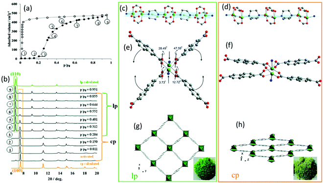 |
| | Fig. 1 (a) Adsorption N2 isotherm at 77 K on DUT-8(Ni) together with the (b) in situ XRPD data. The obtained structural characteristics of the lp and cp structure: (c and d) the Ni paddle-wheel chains pillared by dabco molecules, (e and f) SBU environment, (g and h) and the resulting crystal structure along rectangular channels. (Reprinted with permission from ref. 16. Copyright © 2020. Published by WILEY-VCH Verlag GmbH & Co. KGaA, Weinheim). | |
Even though the XRPD technique is limited to samples possessing a long-range order and therefore is not well-suited for the investigation of the early stages of MOF and zeolite formation, nucleation, and growth processes of both zeolites and MOFs have been studied.19,20 The requirements for the in situ setup for a typical solvothermal synthesis are the resistance of the reaction cell against elevated temperatures and pressures while being X-ray transparent.20 For the latter and a better time resolution, the use of synchrotron radiation with tits high flux is beneficial.14,19 To reduce the data acquisition time further to minutes or even seconds, most crystallization studies of MOFs are performed by energy-dispersive X-ray diffraction (EDXRD).19 Here, a polychromatic source that is fixed at one scattering angle is used, and the measured signal is recorded as a function of the scattered intensity. Because of the experimental geometry, the measured sample volume can be fixed in the reactor, thus, avoiding the scattering contributions of the reactor itself. However, the spatial resolution of this technique is reduced compared to conventional XRPD. Recently, it was shown that from time-resolved angle-dispersive X-ray diffraction (ADXRD), where multiple angles are measured, diffraction patterns can be extracted.19 Here, acquisition times of ∼1 frame per second could be achieved.
Recently, the mechanochemical synthesis of MOFs has been established.21–30 Mechanochemistry is defined by the International Union of Pure and Applied Chemistry (IUPAC) as the term for any chemical reaction which is induced by the direct energy transfer from milling media (milling jar and balls) onto the reactants.31 Through this direct and strictly local energy transfer, the use of solvent can be reduced or even completely avoided. Therefore, mechanochemistry is considered an environmentally friendly reaction pathway. However, through the strictly local energy transfer, the reaction mechanism and as such also the reaction often differs from conventional thermal, pressure-, and/or solvent-based synthesis approaches. Modifications of the dry or neat mechanosynthesis are the liquid-assisted grinding (LAG), the ion- and liquid-assisted grinding (ILAG), or polymer-assisted grinding (POLAG). All methods were successfully applied to form co-crystals, zeolitic imidazolate frameworks (ZIFs), and MOFs.21,32 We want to highlight some pioneering work in the field. For detailed information, we recommend the following publications of Do and Friščić,33 Friščić et al.,34 Halasz et al.,23 James et al.,35 Tan and Friščić,36 Uzarevic et al.27 and Michalchuk and Emmerling.31 The first successful in situ XRPD monitoring of the formation of nanoporous material was performed by Friščić et al.21 The authors studied the formation of different ZIF-structures (ZIF-4, ZIF-6, ZOF-8) in self-constructed milling vessels made from X-ray transparent poly-methylmethacrylate (PMMA). In this setup, they were able to study the effect of different organic liquids and ionic additives on the reaction kinetics. Batzdorf et al. could show the benefit of coupling XRPD and Raman spectroscopy (Fig. 2) to obtain information about the crystalline and molecular compounds in the reaction mixtures.37 For the synthesis of cobalt(II) phenylphosphonate monohydrate (CoPhPO3·H2O), cobalt(II) acetate tetrahydrate and phenylphosphonic acid were mixed and then exposed to milling conditions. Through the combination of Raman spectroscopy and XRPD, a two-step formation with a layered intermediate phase was revealed. After the formation of the intermediate, no scattering contributions of the phenylphosphonic acid could be observed in the XRPD. However, the Raman data show that the acid is acting as a template between the layers. The product is observed already after 2.75 min and the reaction is completed after 27 min.
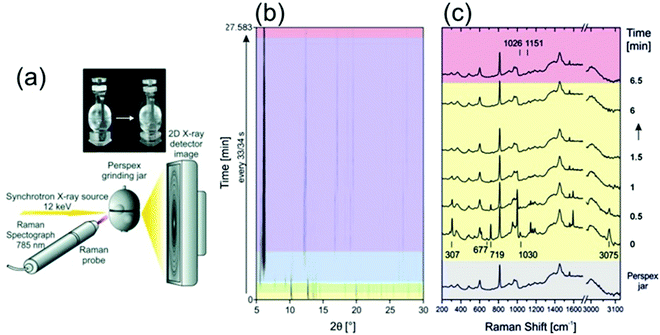 |
| | Fig. 2 (a) A schematic representation of the experimental setup for recording Raman and XRPD data simultaneously during mechanochemical processes. (b) In situ synchrotron XRPD data and (c) simultaneously collected Raman spectra collected during the mechanochemical synthesis of CoPhPO3·H2O. (Reprinted with permission from ref. 37. Copyright © 2015 WILEY-VCH Verlag GmbH & Co. KGaA, Weinheim.) | |
Total scattering and subsequent pair distribution function (PDF) analysis
Total scattering is an analytical tool for the analysis of local atomic structures of crystalline, disordered and/or amorphous materials as well as of liquids and gases. Since it is not well established for the analysis of nanoporous materials, some more background information on this technique will be given. Total scattering experiments do not only consider Bragg reflections but also diffuse scattering, which contains information about the local atomic structure. Usually, diffuse scattering is considered unwanted background and is therefore often simply removed. However, one should not do that, if the local structure is of interest. From the Fourier transform of total scattering data, the so-called pair distribution function (PDF) analysis is obtained. The PDF is the weighted probability to find atoms at certain distances from other atoms. This is called atom–atom correlations or pair–distance distribution function (Fig. 3).38 To obtain a high resolution, total scattering data are collected to high diffraction angles (high Qmax). For this reason, radiation with a small wavelength and high energy as provided by synchrotron facilities is preferred. After data collection, data need to be corrected and normalized before the Fourier transform is applied to result in the pair-distribution function (PDF).39,40 While extended X-ray absorption spectroscopy (EXAFS) is limited to local structure analysis within a spatial range smaller than 5 Å, total scattering collects all structural information of a particle. In addition, the element sensitivity of EXAFS is based on measuring the absorption spectrum near the absorption edge of one specific element. Complementary, PDF is not element specific but measures all structural details independent of all elements present. The method was developed after Friedrich measured broad diffraction rings for non-crystalline materials and Debye formulated his famous Debye scattering equation.41,42 However, due to instrumental limitations, the method was rarely used for the following decade but gained increasing interest in the 1980s with the improvement of instrumental and computational power.39,43 Warren and co-workers applied total scattering techniques to crystalline materials and it became more and more interesting to study not only average crystal structures but also local structures of, say, disordered zeolites or glasses.44 Since working with nanoporous materials implies the use of powder diffraction for structure analysis, the extension of total scattering to nanomaterials was a decisive step.45–48 For the local structure analysis of zeolites, total scattering can provide beneficial insights. In general, within the alumosilicate framework of zeolites, Al and Si ions are randomly distributed. Since they are next neighbours in the periodic table it is hard to differentiate them by their scattering power in an X-ray experiment. Both elements have low atomic numbers, which makes XAFS measurements difficult, and NMR signals get broad when the Al and Si coexist.49 However, looking closer to the crystal structure on a local scale, the Si–O bond (∼1.60 Å) is shorter than the Al–O bond (1.74 Å) by around 0.14 Å. In a high real-space resolution PDF measurement of calcium aluminosilicate glasses, it was possible to resolve Si–O and Al–O pair correlations. One of the first studies using total scattering and subsequent PDF analysis was published by Martínez-Iñesta et al.50 Zecolite beta with its polymorphic structures is known to be a very challenging material for conventional structure analysis. The authors performed structure refinements of zeolite beta using the local structure obtained with the PDF method. They collected high-quality synchrotron and neutron scattering datasets. Even though the materials lack long-range order, they could show that the two polytypes of zeolite beta have the same local structure. The method enables studies on the crystallization of nanoporous materials starting from amorphous precursor phases to crystalline products. Another pioneering PDF work on microporous materials was published by Okubo and co-workers who studied ring-formation during the crystallization of zeolites.51 Local structures of zeolites can be examined by solid-state nuclear magnetic resonance (NMR) spectroscopy or extended X-ray absorption spectroscopic (EXAFS) techniques, but the structural information obtained by these methods was not sufficient to determine the nature of the ring structure. Therefore, they applied X-ray total scattering in combination with reverse Monte Carlo (RMC) modeling to investigate the atomic arrangement of precursor species during the crystallization of different zeolites.51 High-energy synchrotron radiation was used for collecting ex situ scattering data. The authors could show that total scattering has a great contribution to the understanding of the nature of ring systems formed during the initial stages of zeolite crystallization and can be applied to any type of solid formed via an amorphous intermediate.
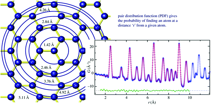 |
| | Fig. 3 Left image sketches the structure model of graphene. Starting from the central atom, circles are drawn at different distances from the central atom. Whenever atoms are intersecting with the circles, a unit of intensity is added to a histogram at the position r which is the radius of the circle (right image). The histogram is broadened due to thermal motion. Blue curve: measured PDF, red line calculated PDF, green curve: difference curve. (Reprinted with permission from ref. 38. Copyright © 2011 WILEY-VCH Verlag GmbH & Co. KGaA, Weinheim.) | |
Another example of a very beneficial combination of techniques is the combination of PDF, NMR, and Raman spectroscopy to probe local chemical bonding. Forse et al. provided an example of the structural characterization of nanoporous carbons.52 The material lacks long-range order and can exhibit diverse local structures. PDF analysis revealed the prevalence of sp2-hybridized hexagonal carbon rings, as well as the presence of seven-membered carbon rings for titanium carbide-derived carbons prepared at low temperatures. The authors also showed the disorder of the carbon–carbon bonds by PDF analysis which was in good agreement with the results obtained from Raman spectroscopy. Another example of how total scattering provides useful information at distances beyond those reliably quantifiable by EXAFS was the encapsulation of molybdenum carbide nanoclusters inside the micropores of zeolite FAU.53 While conventional X-ray powder diffraction measurements could not prove the presence of Mo2C clusters due to the too small size of the Mo2C entities inside the zeolite pores, differential PDF analysis revealed the presence of MoCx nanoclusters smaller than 0.7 nm within the pores.
Even though total scattering was used for local structure analysis, today still most studies are based on ex situ data. Kalantzopoulos et al. published one of the first studies on in situ temperature-dependent total scattering experiments during the exposure of SAPO-34 to water in combination with in situ NMR studies.54 The work aimed to understand the dynamic nature of the Brønsted acidic site and its close surroundings during interactions with water molecules. In situ NMR revealed that the Brønsted proton becomes highly dynamic and in the same temperature range, PDF analysis monitored changes in the Al local environment between 250–300 °C as the Al–O bond lengths change (Fig. 4). In situ total scattering experiments could also be used to follow an alternative synthetic route for zeolites by the Assembly, Disassembly, Organisation, and Reassembly (ADOR) process.55 During the transformation process of parent zeolite Ge-UTL, crystallographic order is lost as 2D layers are formed. The in situ PDF experiments were performed at a synchrotron beamline using a custom-made liquid cell adapted for X-ray transmission.56 The PDF data monitor the hydrolysis (disassembly) and rearrangement (organization) mechanisms in the ADOR process for three aqueous systems with different concentrations of HCl. The PDF of parent Ge-UTL shows broad T–O and T–T pair correlations because the bonds of both Si and Ge contribute to the peaks (Fig. 5a). Disassembly in water is a fast process and once Ge has been removed from the structure, the disordered layered IPC-1P is formed. Another experiment was performed in an aqueous solution with 6 M HCl (Fig. 5b). One new peak appears at 2.08 Å, which is assigned to the formation of a new Ge–Cl bond, together with another extra peak at 3.5 Å, which likely corresponds to the nearest neighbouring Ge–Ge bonds. This has not been observed before by conventional ex situ diffraction studies. Based on the in situ data, it was concluded that Ge is not only hydrolyzed by water but that a high concentration of [H+] and [Cl−] accelerates the process and plays an important role in the disassembly mechanism by attacking the D4R unit.55 One last example of in situ PDF analysis is the monitoring of the structural evolution of precursors to crystalline zeolites.57 Two different zeolites, MFI and *BEA were synthesized under hydrothermal conditions using a microwave reactor. The reactor which was used for the in situ studies at the high energy synchrotron was modified to allow X-rays to pass through the glass vial with minimum background interference (Fig. 6). Simulations of the crystal structures and electron micrographs are shown in Fig. 7a–d. For both zeolites, the PDFs demonstrate that the final products in the range <6 Å, resemble each other (Fig. 7e and f). Even though the two structures are essentially different, the linkages of the silicate units are similar as well as the fractional distribution of small-membered rings. Changes in the medium-distance range >4 Å obtained for both zeolites indicate the formation of larger ring structures due to the reassembly of the alumosilicate species during the induction period. An increase in the more ordered rings formed during the induction period seems to enhance the nucleation of the zeolites (Fig. 7g). Finally, the authors could not detect changes in the long-distance range for both zeolites before apparent crystal growth takes place.
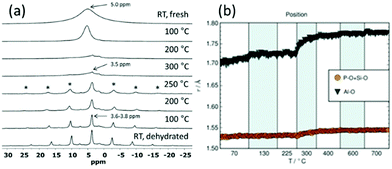 |
| | Fig. 4 (a) 1H NMR spectra from RT up to 300 °C (top half) and from 300 °C down to RT (bottom half) in flowing dry N2 gas. Spinning sidebands are marked with *.(b) Variations in the Al–O, P–O (and Si–O) bond lengths. (Reprinted with permission from ref. 54. © 2018 Wiley-VCH Verlag GmbH & Co. KGaA, Weinheim.) | |
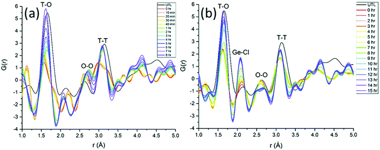 |
| | Fig. 5 Time-dependent experimental PDFs were collected (a) during 8 h of hydrolysis at 100 °C of UTL in water, (b) during rearrangement of UTL treated in 6 M HCl within 15 h at 100 °C. (Reprinted with permission from ref. 55. Copyright © 2018, The Royal Society of Chemistry.) | |
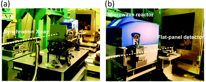 |
| | Fig. 6 Photographs of the experimental setting for in situ X-ray total scattering measurements at BL08 W (SPring-8). The photographs show the beam path through the vias (a) and the position of the vial fixed in the microwave reactor (b). Scattering data were recorded every 60 s. (Reprinted with permission from ref. 57. Copyright © 2017, American Chemical Society.) | |
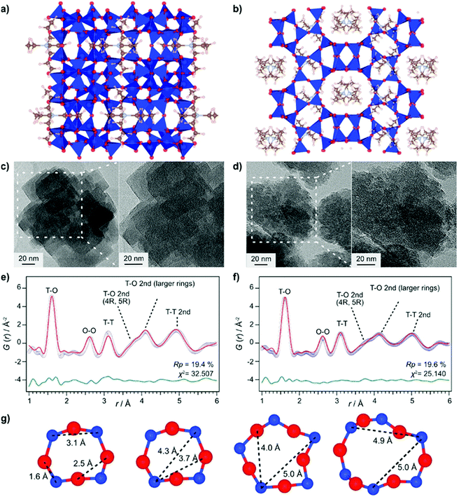 |
| | Fig. 7 Structure models of (a) MFI and (b) *BEA. Transmission electron micrography images of (c) MFI and (d) *BEA. Refined ex situ PDF data for (e) MFI and (f) *BEA zeolites. Experimental data (blue circles), simulated PDF (red lines), and difference curve (green curve). (g) Typical ring structures of MFI; T-atoms: blue, O-atoms red. (Reprinted with permission from ref. 57. Copyright © 2017, American Chemical Society.) | |
In situ SAXS
Small angle scattering (SAS) is an important tool for the characterization of nanoporous materials, especially mesoporous materials. In principle, SAS is a measure for the interaction of radiation with matter, more precisely the interaction with electron density variation in the matter. For small angle scattering experiments, among others, X-rays (small angle X-ray scattering, SAXS), neutron radiation (small angle neutron scattering, SANS), or electrons (small angle electron scattering, SAES) are used. One particular advantage of SAS is that it can resolve structures in the order of 1 to more than 100 nm.58 In addition, it delivers information about the size and shape of matter irrespective of whether the material is crystalline or amorphous. Furthermore, SAXS is an alternative and complementary approach to gas adsorption experiments for reliable and fast surface area assessment.59 For a deeper reading numerous review articles provide excellent overviews of the physical background, technical issues, and examples of use.60–63 The application of in situ SAXS is mainly used to study formation pathways during the crystallization of porous materials as well as to monitor adsorption processes in nanoporous compounds. In 2011 in situ SAXS and in situ wide-angle X-ray scattering (WAXS) were combined for the first time to study the crystallization of two metal–organic frameworks synthesized from similar metal and organic precursors, NH2-MIL-101(Al) and NH2-MIL-53(Al).38 The authors used a synthesis cell with two diamond or mica windows (10 mm diameter) separated by 1.5 mm thick polymer spacers (polytetrafluoroethylene, PTFE) between which the solution was loaded. Heating was provided by electrical resistance heaters and high-intensity synchrotron radiation enabled the simultaneous collection of SAXS and WAXS data every 20 s. The combined measurements provided information on how the crystallization of MIL-101 takes place on different length scales. The modification of the synthesis conditions could be directly correlated to the topology of the product. The studies revealed the formation of an intermediate phase (MOF-235) and only the stabilization of this phase by dimethylformamide (DMF) lead to the successful synthesis of MIL-101 (Fig. 8).
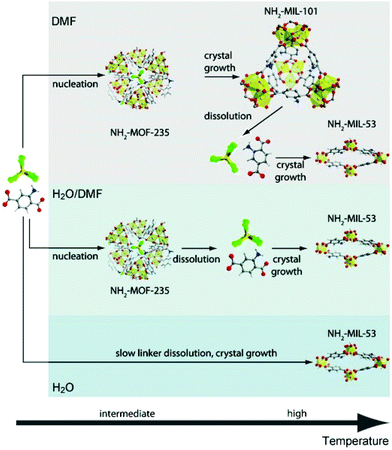 |
| | Fig. 8 Sequence of events during the crystallization of terephthalate-based MOFs in different media: low precursor concentrations (DMF); high precursor concentrations (H2O/DMF or H2O). C: grey, H: white, N: blue, O: red, Al: yellow, Cl: green. (Reprinted with permission from ref. 38. Copyright © 2011 WILEY-VCH Verlag GmbH & Co. KGaA, Weinheim.) | |
Stoeckel et al. performed in situ SAXS during the adsorption of organic vapour (dibromomethane, DBM) in the pores of different mesoporous chromatographic silica adsorbents together with state-of-the-art nitrogen physisorption.64 They could distinguish between varying surface modifications of the materials and their consequences on the adsorption process, especially the uptake of DBM. One important outcome of the study was that the smallest pores are filled first. The combination of physisorption and SAXS is especially valuable for evaluating the pore structure and the pore-filling mechanism in mesoporous materials. The high dynamics of vapour adsorption were studied by Schmidt and Amenitsch using in situ synchrotron SAXS for the adsorption of dichloromethane in ordered mesoporous carbon CMK-5.65 The dynamics of the adsorption process are going along with substantial rearrangement of both the adsorbent phase and the adsorbate phase (Fig. 9). The change of the lattice parameters reveals that the carbon nanotubes of CMK-5 contract and expand during adsorption. This is related to a decrease and increase in the average distances between the tubes. The work also could show that first the interstitial pores are filled before adsorption continuous in the tubular ones.
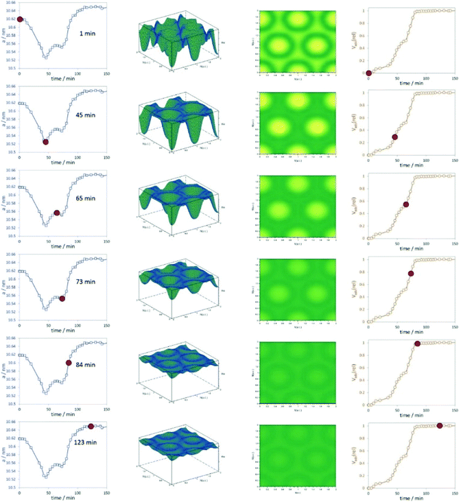 |
| | Fig. 9 Left graphs represent the change of the unit cell parameters with adsorption time, the 3D and 2D representations of the electron densities are shown in the centre, and the relative volume adsorbed is plotted in the right column. The red dots indicate unit cell parameters and Vads(rel) at the respective time intervals. (Reprinted with permission from ref. 65. Copyright © 2020 American Chemical Society.) | |
Recently, the formation of mesoporous metal films by electrodeposition was studied by simultaneous in situ SAXS and electrochemical measurements.66 A specially designed electrochemical cell allowed in situ measurements of the working electrode during the deposition of a lipid-templated platinum nanostructure as the platinum nanostructures grow within the lipid template. The authors could monitor both, the structure of the platinum deposition and the lipid template. The analysis of structural ordering could be correlated with the charge passed during electrodeposition. Usually, SAXS is used to probe the 3D pore architecture of mesoporous bulk material but nowadays nanoporous structures are often produced as films, which cannot be measured using conventional transmission SAXS. In transmission geometry, thin mesoporous films deposited on a substrate do not provide enough sample volume to obtain reasonable signals and the substrate itself contributes to high background scattering. Grazing incidence SAXS or SANS (GISAXS or GISANS) was proven to be an effective method for the characterization of thin films and surface structures. GISAXS is essentially SAXS applied to surfaces in reflection geometry instead of transmitting through the sample.67,68 For GISAXS experiments, the incident X-ray beam is directed to the sample at very small incident angles, typically on the order of 0.05 to 1°. This enables the probing of the structural features from the thin film with a sufficiently long path length (Fig. 10). Modern 2D detectors record the intensity of the two reflection angles αf and 2θ. αf corresponds to the out-of-plane scattering which contains information on the normal-to-film surface direction. The in-plane scattering intensity measured at 2θ provides information on the repeating unit structure parallel to the surface of the substrate.68
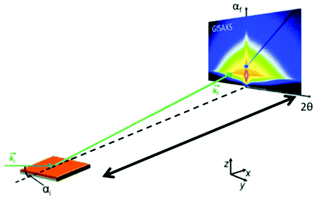 |
| | Fig. 10 Geometry of a GISAXS experiment. The angle of incidence of the primary beam on the specimen is very small close to the critical angle of total reflection. The scattering from the sample was recorded with an area detector. (Reprinted with permission from ref. 68. Copyright © 2020 American Chemical Society.) | |
SAXS at synchrotron sources, and nowadays also with laboratory instruments, has been used for many decades but SANS has not received too much attention in the community working with nanoporous materials so far. This is a pity because the method offers many options for the study of porous materials. If neutrons instead of X-rays are used, the penetration depth of the radiation is increased which allows the use of complex sample environments. Neutron scattering methods enable the measurement of both structure and dynamics simultaneously.61 Inelastic and quasielastic neutron scattering (INS and QENS) provide the rotational, vibrational, and diffusion dynamics of the adsorbed molecule. Neutron spectroscopy measurements typically require longer measuring times and therefore time-resolved measurements are relatively scarce. The use of contrast variation SANS enables different parts of a sample can be selectively displayed via isotopic labelling.58 As an example, the exchange of hydrogen (1H) by deuterium (2D), which is a strong scatterer for neutrons, makes SANS interesting for the analysis of hydrogen-containing organic but also inorganic compounds. Self-assembly of organic species in solution as well as dense network structures surrounded by a less dense medium can be studied by SANS. However, two issues limited the use of SANS for a long time: (a) larger sample amounts and (b) longer measuring times compared to SAXS were required for neutron scattering experiments. Nowadays, fast SANS studies with a time resolution of less than 100 ms are possible and time-dependent SANS experiments became therewith feasible. Boukhalfa et al. published the first in situ SANS study during the electroadsorption of organic electrolyte ions into carbon pores of different sizes.69 The setup used for in situ SANS is shown in Fig. 11. An aqueous H2SO4 solution was used as the electrolyte. In addition both water, H2O, and heavy water, D2O, were used. The reason for this was that the neutron scattering length density (SLD) of H2O and C are significantly different while there is only a small difference in the neutron SLD between D2O and C. The work showed that in situ SANS can be used to directly visualize changes in the electrolyte ion concentration in the pores as a function of the potential applied to any nanoporous carbon material. The method also offers the ability to study the influence of different pore sizes and surface chemistry independently. Applying a negative potential to the working electrode (WE) in the aqueous H2SO4 solution increases the hydrogen concentration close to the WE due to the replacement of HSO4− or SO42− by H3O+. Increases due to increasing scattering contrast as hydrogen-containing species are present in the pores (Fig. 12a). The hydrogen-rich cations will be replaced when a positive potential is applied to the WE, thus decreasing the hydrogen concentration close to the surface and decreasing the scattering intensity. Exchanging H2O with D2O decreases the scattered intensity significantly because neutron scattering length density (SLD) of D2O and C are very similar (Fig. 12). Data analysis showed that the smallest pores exhibit higher ion adsorption capacity at negative potentials. Then a higher H concentration was detected whereas a lower H concentration was obtained at positive potentials.69
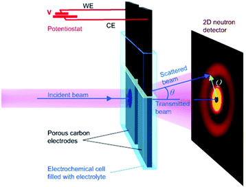 |
| | Fig. 11 Experimental setup for in situ studies of ion adsorption on the surface of microporous carbon electrodes. (Reprinted with permission from ref. 69. Copyright © 2013 WILEY–VCH Verlag GmbH & Co. KGaA, Weinheim.) | |
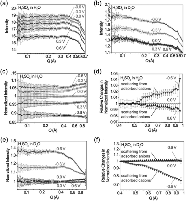 |
| | Fig. 12
In situ SANS patterns of porous carbon electrodes with (a) H2O and (b) D2O-based electrolytes during the application of a potential between the working electrode and the counter electrode. SANS profiles normalized by 0 V for (c) H2O and (d) D2O. (e) and (f) relative changes in the intensity of the normalized SANS profiles. (Reprinted with permission from ref. 69. Copyright © 2013 WILEY–VCH Verlag GmbH & Co. KGaA, Weinheim.) | |
Electron microscopy (EM)
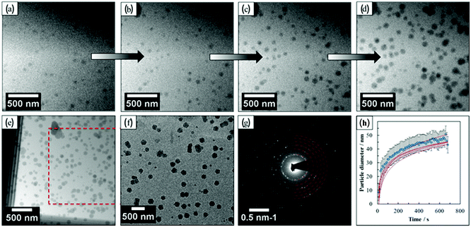
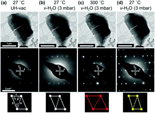
Transmission electron microscopy (TEM) is the most widely used technique to visualize nanomaterials. Sub-nanometer resolution of TEM allows the direct picturing of even small pore structures.70 Over the last decade, tremendous progress was achieved in spherical and chromatic aberration corrections, electron gun performance with a higher energy resolution, detectors, imaging algorithms, and cameras. These developments enhanced the energy resolution capabilities and especially the spatial resolution of TEM measurements.71–74 As described above, most synthesized porous materials, such as zeolites, MOFs, and COFs, are polycrystalline with small crystallite sizes preventing the structure determination via single-crystal X-ray diffraction.10–12 Even though structure solution from powder data is possible, overlapping reflections and large unit cells, as well as the often disordered nature of these porous materials are challenging. However, electrons show a far stronger interaction (Coulomb interactions) with the matter, so that even small entities can be measured. Unfortunately, these strong Coulomb interactions might result in temporary or permanent structural changes (atom displacements or electronic excitations) for beam-sensitive materials, as often encountered for porous materials.74 So-called beam damage can be divided into knock-on sputtering (direct electron–nucleus interaction) causing atomic displacements, radiolysis (electron–electron interaction) inducing bond breaking, and heating due to collective crystal lattice vibration from high energy electrons striking atoms in the specimen.75,76 To reduce the beam damage, cryo-TEM or environmental TEM (ETEM) can be used.75,77 In cryo-TEM, low-temperature imaging reduces the radiolytic and heating damage for beam-sensitive materials.74Via cryo-TEM, the crystallization and growth of the zeolites in the solution can be monitored.78 Therefore, a small portion of the synthesis solution is “frozen” in ethane and imaged at regular time intervals, allowing snapshots of the synthesis procedure at the given time.79 A similar application for cryo-TEM is investigating the formation of hollow zeolite crystals. A ZMS-5 is desilicated with NaOH resulting in a ZSM-5-like compound consisting of an aluminium-rich shell.80 By sampling the desilication experiment in 15 min intervals, Li et al. could observe the formation process of multiply pores that converge to form one cavity (Fig. 13). The formation of beam-sensitive porous materials can also be followed by in situ liquid cell transmission electron microscopy.75,81 Commercial LC-TEM holders allow a fluid flow through the holder.82 The holder is equipped with two 50 nm thick electron-transparent SixNy windows. In addition, the integrated chips can have circuits to allow heating. They also enable electrochemical measurements. Patterson et al. monitored the dynamics and the growth of MOFs/ZIF-8 in real-time for the first time (Fig. 14).81 The growth rate of the particles could be obtained directly from imaging while the crystal structure of the resulting product could be determined via electron diffraction (ED). An effect of the electron beam on the crystal growth could be ruled out by comparison with similar systems under standard bulk solution conditions. The obtained results indicated an influence of the used metal precursors and ligands on the particle growth and such on the particle size. The particle growth, as well as the nucleoid formation, could be controlled over the flow of the monomer solutions into the cell. Thereby, the authors could demonstrate that physical agitation, not the electron beam can cause reproducible differences in the nuclei number. For performing ETEM measurements, the microscope is equipped with a differential pump system to allow a gas atmosphere around the specimen while maintaining a low pressure in the electron path.77 With modern TEM instruments and mostly specially designed TEM sample holders, in situ and operando investigations are possible allowing the establishment of not only the bulk structure but also local structure–property relationships.71,73,74,83,84 This setup can be combined with different in situ sample holders (e.g. heating or cooling) but the general gas pressure has to be kept low to maintain the high vacuum. Parent et al. could directly monitor the breathing behaviour at the lattice level of a single MIL-53(Cr) nanocrystal during water adsorption/desorption with a combination of ETEM plus electron diffraction (ED) and molecular dynamics (MD) simulations (Fig. 15).85 The empty MIL-53(Cr) framework compound can be described in Imma at 27 °C. At ∼3 mbar water vapour pressure, no significant changes were observed (Fig. 15a and b). Annealing the MIL-53(Cr) at 300 °C in water vapour results in the adsorption of one H2O molecule per unit cell in the channel system going along with a lowering of the symmetry to P21 (Fig. 15c). During cooling to 27 °C, the specimen adsorbs additional 24 water molecules (per unit cell) in the channel system resulting in lattice changes and an additional lowering of the symmetry to P1 (Fig. 15d).85 As mentioned before, most synthesized nanoporous materials are polycrystalline, thus preventing structural analysis by conventional X-ray diffraction methods. However, because of the described strong Coulomb interactions of electrons and matter, much smaller entities (10–20 unit cells in each direction) can be investigated by three-dimensional electron diffraction (3DED) techniques.10–12,86 Unfortunately, these strong interactions also cause multiple scattering of electrons strongly influencing the observed intensities.10,11,86 The groundbreaking step forward in the 3DED techniques was the possibility to rotate a crystal stepwise (angular steps 1.0°–2.0°) along an arbitrary axis while collecting ED patterns at each angle.10,11,86 Two different approaches were developed simultaneously, the automated diffraction tomography (ADT) in STEM mode by Kolb et al.87–90 and the rotation electron diffraction (RED) in TEM mode by Hovmöller et al..91,92 In the ADT approach, the goniometer tilt and the applied beam precession using the beam tilt deflectors, also called precession electron diffraction tomography, (PEDT) are applied to obtain a fine sampling.10–12,87–90 With the RED software, both the goniometer and the electron beam can be controlled.10,11,91,92 The reconstruction of the 3D reciprocal space from the 2D ED patterns at different angles allows the determination of the unit cell and the space group. After indexing the reflections and extracting their intensities, the crystal structure can be determined with a method similar to single-crystal X-ray data analysis (e.g. direct methods, charge flipping).12 Another advantage of these approaches is that the crystals do not have to be aligned at a zone axis, which simplifies the measurement, reduces data collection time, and, most importantly, reduces dynamical effects. Together these advantages allow the usage of similar routines for structure determination as for single-crystal diffraction with X-rays. The often observed electron beam sensitivity of porous material can cause the decomposition of the materials, which may significantly reduce the data quality. However, this problem can be overcome by continuous rotation data collection.93,94 By adjusting the rotational speed of the goniometer and the use of a fast detector, a complete data set can be recorded within minutes or even seconds (15–250 s).10–12 Combining these fast measurements with a low electron dose rate (<0.1 e s−1 Å−2), the electron dose on the sample can effectively be reduced.10–12,86 Due to sample drift and goniometer tilt, it is difficult to keep exactly the same crystal area selected for data acquisition during continuous operation. However, by defocusing the diffraction patterns at regular intervals and re-centring the crystal either manually or automatically the crystal can be tracked.10–12 Mugnaioli et al. were able to perform the ab initio structure determination of cowlesite (Ca6Al12Si18O60·36H2O) via 3D ED
from single-crystal domains of a few hundred nanometers (Fig. 16).95 Unlike other natural zeolites, the crystal structure of cowlesite could not be determined with X-ray diffraction techniques, because of its way too small crystallite sizes, its large unit cell, and strong overlapping reflections. When cowlesite is exposed to the high vacuum in a TEM instrument, a phase transition occurs leading to a dense zeolite framework within seconds. A cryo-plunging procedure was used to embed the crystallites in amorphous ice, thus sealing its pores and preventing the release of water and the phase transition. Through this approach, the authors could show that the crystal structure of cowlesite consists of rigid zeolitic layers intercalated with water molecules and extra framework cations (Fig. 16e and f). An additional ED technique for the structural analysis of nanovolumes and disordered compounds is the electron pair distribution function (ePDF). Through the flexibility in the electron diffraction camera length and modifiable electron wavelength, the necessary large scattering range can be explored. The described strong Coulomb interactions are beneficial for the recording of ePDF of particular small entities or poorly crystalline samples with insufficient long-range order for obtaining X-ray diffraction data of sufficient quality for structure analysis.96–98 In addition, the electron beam can be focused down to 3 nm, by applying spherical aberration correction even down to 1 nm, allowing the investigation of the local atomic structure of samples.98 The inelastic scattering and the possible multiple scattering of electrons contribute to the ePDF data which may affect the reliability of the obtained scattered intensity profiles. The inelastic scattering mainly affects the background of the recorded data. Its influence can be reduced by using an electron energy loss spectroscopy (EELS) detector.98 Multiple scattering mainly affects the experimental intensity (particularly at higher angles). However, multiple scattering is insignificant if the electron mean free path is greater than the crystal size. Beam damage of sensitive samples can be avoided by cryo ePDF, similarly to cryo TEM measurements.76 Jasim et al. introduced the first cryo ePDF study, investigating amorphous AlOx coatings that suffered severe beam damage at ambient temperature. With cryo ePDF, the authors could analyze the effects of the deposition temperature on the structure and the surface hydroxyl density.76 Scanning electron microscopy (SEM) is a common technique to observe and quantify the particle shape, surface texture, and particle contribution of nanoporous compounds. In particular, the great depth of the field of view allows the direct visualization of three-dimensional information, such as morphology and topography. The composition of nanoporous materials can be identified simultaneously with energy-dispersive X-ray spectroscopy (EDX) analysis.83,99 In principle, similar in situ sample holders as developed for TEM can be used in SEM.100 In addition, SEM can also be coupled with a focused ion beam (FIB) cutting/sectioning to investigate the internal mesoscopic 3D structures of different compounds.100,101 A FIB-SEM measurement can be classified in FIB-SEM processing, imaging analysis, and quantitative 3D reconstruction. The specimen is sectioned/milled with FIB so that SEM images from the exposed cross-section can be recorded.101 The data acquisition and the reconstruction of the quantitative 3D tomograph are fully automated. FIB-SEM can be combined with electron dispersive spectroscopy (EDS) and electron backscatter diffraction (EBSD) systems to simultaneously analyze chemical, crystallographic, and topological data. Bae et al. investigated the complex pore system of a commercial zeolite absorbent, consisting of zeolite beads filled with small internal beads, nicely showing the flexibility of FIB-SEM to analyze a variety of microstructural features simultaneously (Fig. 17).102 Tomography X-ray computed diffraction tomography (XRD-CT) is a non-destructive technique to reconstruct 3D images or 4D movies with a spatial resolution in the sub-micrometre to nanometre range. The specimen is illuminated with a highly collimated monochromatic X-ray beam and diffraction patterns are recorded while the specimen is translated and turned. The resolution of the measurement is thereby directly correlated to the spot size of the beam. Triggered by the development of X-ray focusing lenses for both, hard and soft X-rays, and the application of coherent synchrochrotron radiation plus efficient area detectors, a resolution in the nanometer range can be achieved.103,104 Together these achievements allow a high-spatial-resolution mapping of the chemical composition, the structure, and the porosity of the specimen.103,105 Wragg et al. investigated the deactivation of shaped zeolite catalyst extrudates (SAPO-34) (Fig. 18).106 They could show that during the catalytic conversion of methanol to hydrocarbons, the activation starts at the external layers of the extrudates and progresses into the bulk. Through the operando monitoring of the deactivation process in both time and space, it was possible to obtain a kinetic model for the coking, providing crucial insight which allows improvement of the catalyst and process design. In line with ex situ studies, these experiments show that the catalyst body only partly gets in contact with the reactants during the catalytic process and only deactivates partly (Fig. 18b). These findings may lead to modifications in the catalyst design, especially with respect to size, active species concentration, and spatial distribution of active species. A recent development is the combination of CT with total scattering plus subsequent pair distribution function analysis for mapping of nanocrystalline material with crystallite sizes smaller than 3 nm.105 Atom Probe Tomography (APT) is a destructive technique performed in an ultra-high vacuum, where an electric field is applied to desorb chemical species. The type and number of desorbing species depend on elements and their nearest neighbours. The desorbed species are recorded on a position-sensitive detector recording their mass-to-charge ratio with time-of-flight mass spectroscopy (Fig. 19a).107 In this way, the chemical identity, as well as the geometrical position of the desorbed species, can be reconstructed. APT is the only tomographic method that allows the 3D chemical analysis of the specimen with atomic-scale resolution and in principle with no limits for light and heavy atoms.108–112 Through the needle shape of the specimen, several facets with different crystallographic orientations are measured simultaneously and the tip can be considered as a model for a single crystal.110 The implementation of different advances greatly enhanced the field of application of this technique, such as the local electrode geometry which improved the field effect, and the use of a reflectron enhancing the mass resolution. The usage of thermal laser impulses for the initiative evaporation allowed the analysis of non-conductive materials.110 The sample preparation via FIB to needle-shaped specimens made it possible to analyze also semiconductors, and even non-conductive materials.109,110 In particular, for non-conducting zeolites with small crystallite sizes, the needle shaping of the analyte via FIB preparation is crucial since a high electric field is needed to introduce the fundamental emissive behaviour such as field emission, field ionization, and/or field evaporation.108,110 During the preparation, the possibility of beam damage of sensitive materials (e.g. zeolites or MOFs) has to be accounted for by minimizing imaging time and the use of protective layers.110,111 In addition, density variations in the specimen can cause local magnification effects in the reconstructed images if hemispherical shapes are assumed. Evaporation field differences may lead to distortion in the spatial resolution resulting in significant errors in the reconstructed images, particularly for composite materials.109 Quantifying the obtained results is challenging due to variation in the probability of simultaneous evaporation in one pulse event, resulting in different detectability of elements and hence incorrect compositions.109 However, the quantitative spatial distribution of silicon (Si) and aluminium (Al) in a zeolitic framework which is crucial for its activity in catalytic processes and selectivity can be investigated with APT.110 Recently, in situ reaction cells for APT have been developed to study catalytic, corrosion, and ageing processes.110 These in situ cells permit
the exposure of the specimen to different gas environments at elevated temperatures, mimicking real reaction conditions while avoiding possible surface contaminations and oxidation reactions. Schmidt et al. investigated in a combinational study using scanning transmission X-ray microscopy (STXM) and APT the ageing of copper-exchanged zeolite SSZ-13 which is applied for NOx reduction in automotive emissions.113 By the combination of these two methods, the preferential removal of tetrahedral Al to form extraframework (octahedral) Al from the center of the catalyst could be detected. Via APT the 3D information of the distribution of the elements could be obtained, while their local coordination environment could be explored via STXM. Recently, Ji et al. presented the first APT measurement of mixed-metal rod-shaped MOF-74 with binary combinations of cobalt (Co), cadmium (Cd), lead (Pb), and manganese (Mn) (Fig. 19).107 The combination of different metals together with variation of the synthesis temperature resulted in different metal distributions: random (Co, Cd, 120 °C), short duplicates of two to four metals (Co, Cd, 85 °C), long duplicates (Co, Pb,85 °C), and insertions of a single metal into duplicates of another metal (Co, Mn, 85 °C).107 Ptychographic X-ray CT (PXCT) is a non-destructive imaging technique combining coherent diffraction imaging (CDI) with STXM.114 CDI is a reciprocal diffraction imaging technique working without lenses. The reconstruction of the real-space complex sample wavefunction from coherent reciprocal-space diffraction intensities is done with advanced iterative algorithms with a strict oversampling criterion.114 In X-ray ptychography, the specimen is scanned, so that the neighbouring scanned areas overlap. Then the illumination wave field and the specimen image are reconstructed.115 Beyond spatial resolution, 3D electron density maps of a specimen can be calculated from the measured phase shift with PXCT.116,117 Since the electron density of known species can be calculated from tabulated mass density values, the recorded images can be directly labelled with the respective materials.116 First, the specimen projections are reconstructed by ptychography, serving as input for conventional tomographic reconstruction of the specimen.117 Recently, these two steps were coupled to improve the scanning overlap requirements, allowing the flexible acquisition of patterns, minimizing the measurement time and thus the radiation dose for sampling.117 Li et al. studied the effect of the base-leaching on the pore formation in ZSM-5 and silicalite- 1 (Fig. 20).118 With PXCT with a spatial resolution of 40 nm, the pore-formation in the crystal could be followed in 3D. The authors could relate the pore formation to compositional and structural properties. In the case of ZSM-5, the usage of the organic templates (TPA+) causes zoning of Al in the framework structure, resulting in the formation of hollow crystals upon leaching. In the comparison of defect-free silicate-1 with a sample showing intergrowth, the dissolution happens preferably on the boundaries of the intergrowth areas in the latter (Fig. 20a and b).
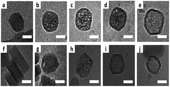 |
| | Fig. 13 Cryo-TEM of ZSM-5 particles leached at 80 °C: (a) pristine crystal, (b and c) mesoporous crystal, (d and e) and the hollow crystal. The bottom row shows the cryo-TEM of ZSM-5 particles leached at 50 °C: (f) pristine crystal, (g and h) mesoporous crystal, and (i and j) the hollow crystal. Scale bars resemble 50 nm. (Reprinted with permission from ref. 80. Copyright © 2019 The Royal Society of Chemistry.) | |
 |
| | Fig. 14
In situ LC-TEM images of ZIF-8 particles. (a–d) Snapshots show the growth of individual particles. (e) Image obtained after the in situ data acquisition: (e) in solution and (f) dried. The red box displays the areas viewed in (a–d). (g) Selected area diffraction pattern recorded from the dried particles grown in the cell. (h) Plot showing the mean growth kinetics of individual particles. (Reprinted with permission from ref. 81. Copyright © 2015, American Chemical Society.) | |
 |
| | Fig. 15
In situ ETEM images of one MIL-53(Cr) nanocrystal (top row) together with the obtained diffraction patterns (middle row) at four different conditions during breathing: (a) 27 °C + UH-vacuum, (b) 27 °C + water vapour, and (c) at annealing to 300 °C in water vapour. At last, (d) after cooling to 27 °C in water vapour. In the bottom row, the determined metric is illustrated: the lattice parameter (a, b, c) and angles (α, β, γ) from the ETEM diffraction patterns. (Reprinted with permission from ref. 85. Copyright © 2017, American Chemical Society.) | |
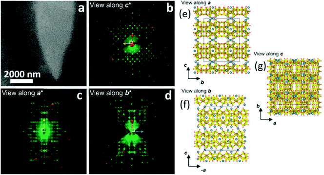 |
| | Fig. 16 (a) STEM images of a cowlesite particle embedded in amorphous ice. (b) Projection of the reconstructed 3D ED data: (b) along c*, (c) along a*, and (d) along b*. (e–g) The determined crystal structure of cowlesite along the three main crystallographic directions. The colour code for the atoms are: Si/Al in yellow, O atoms in red, and Ca atoms in blue. (Reprinted with permission from ref. 95. Copyright © 2020 American Chemical Society.) | |
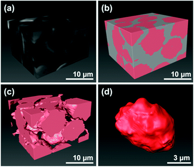 |
| | Fig. 17 Microstructure images of the zeolite-epoxy pellet after 3D reconstruction: (a) stacked the FIB-SEM images, (b) colour-mapping zeolite phase in pink and the epoxy-filled pore in grey, (c) after removing the epoxy phases, (d) one isolated single zeolite bead from the reconstructed 3D specimen. (Reprinted with permission from ref. 102. Copyright © 2022 Springer Nature Switzerland AG.) | |
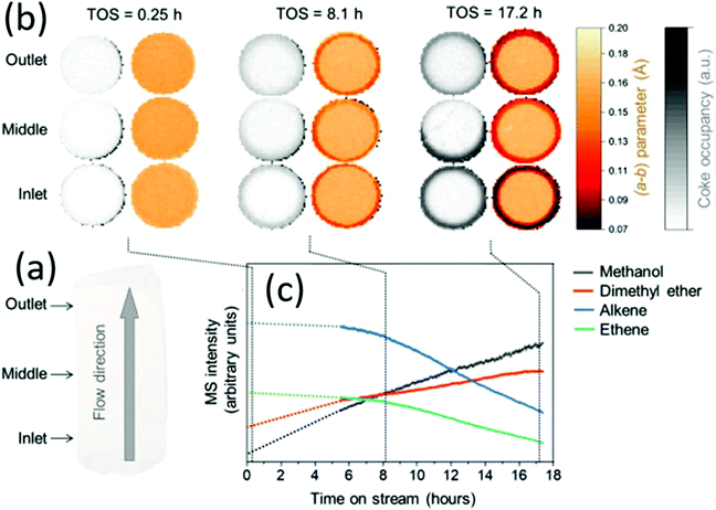 |
| | Fig. 18 Mapping the coke formation within a zeolite catalyst extrudate by operando computed X-ray diffraction tomography. (a) Three horizontal slices of catalyst (1.6 × 6 mm) were measured at different marked positions of the reactor inlet. (b) Time-depending tomograms show the evolution of the a–b parameter and the coking derived from the residual electron density. (c) Time-depending mass spectroscopic data showing the catalyst activity and deactivation, respectively. (Reprinted with permission from ref. 106. Copyright © 2021, Elsevier Inc. All.) | |
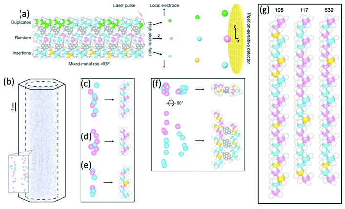 |
| | Fig. 19 (a) Schematic drawing of APT technique with the position-sensitive detector to determine the type of metal sequences that exist in mixed-metal MOFs. (b) 3D-APT reconstruction from a single crystal of Co, Cd-MOF-74 in 3D together with a zoom of the determined metal chains in the inlet. (c–e) Reconstituted metal chains extracted from the raw data: (c) a good match, (d) a redundant metal, and (e) a missing metal. (f) The reconstituted rods of neighbouring metal chains are connected by organic linkers. (g) The metal–oxide rods reconstituted from different metal chains. Color code: Co (blue); Cd (pink); missing metals (orange); O (white); C (gray). (Reprinted with permission from ref. 107. Copyright © 2020, The American Association for the Advancement of Science.) | |
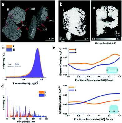 |
| | Fig. 20 Ptychographic X-ray CT of base leached silicate-1 zeolite crystals. (a) Volume rendering of the acquired electron density tomograms and (b) central cut slices through the tomograms. (c) Corresponding electron density histogram. The selected segmentation threshold to isolate leaching introduced pores from the zeolite at the attained spatial resolution. (d) Averaged pore size distribution of the zeolite. (e) Radially averaged electron density changes in direction of selected crystallographic facets. (Reprinted with permission from ref. 118. Copyright © 2019, American Chemical Society.) | |
Solid-state nuclear magnetic resonance (NMR) spectroscopy
As a local probe, solid-state nuclear magnetic resonance (NMR) spectroscopy is ideally suited to study nucleation and crystallization/growth processes of nanoporous materials or catalytic reactions between gas phases and solid porous catalysts.9 Moreover, structural phase transformations under non-ambient conditions as well as catalytic conversion can be followed by in situ NMR.119–122In situ solid-state NMR spectroscopy is an appropriate tool for the investigation of molecules adsorbed at solid–liquid interfaces. One example is the adsorption of glucose and the subsequent isomerization to fructose and mannose inside a faujasite zeolite.123 The isomerization is catalyzed by zeolites NaX and NaY where water is mixed with a small amount of an organic cosolvent, γ-valerolactone (GVL). Temperature- and pressure-dependent NMR measurements study the influence of the concentration of the organic cosolvent on the adsorption behaviour. If glucose is dissolved in pure water, the 13C (magic-angle spinning) MAS NMR spectrum consists of two C1 signals representing two glucopyranose tautomers which dominate in the bulk solution at 298 K. However, if is glucose dissolved in GVL, the NMR spectrum shows four distinct C1 signals. The two sharp signals represent highly mobile glucopyranose tautomers in the bulk solution, while the two broad signals arise from the same tautomers confined inside the zeolite pores. The broader line width is caused by limited mobility and/or inhomogeneous adsorption in the pores. Low GLV concentrations suppress glucose adsorption, glucose is depleted in the zeolite pores. This changes the local structure of co-adsorbed water and leads to a decrease in the isomerization rate. At higher GVL concentrations, there is a significant enrichment of both water and glucose in the adsorbed phase, indicating that both components prefer the zeolite pores over the GVL-rich liquid phase. Magic-angle spinning (MAS) NMR spectroscopy is a tool providing information on the local structure of intermediates and products formed during the synthesis of nanoporous materials, such as zeolites, zeotypes, metal–organic frameworks, or mesoporous materials. In addition, MAS NMR can differentiate between different species in solution and solid-state.124 Usually, crystallization studies of zeolites or other porous materials have been performed by interrupting the syntheses after certain times, and taking samples out of the reaction system and transferring them to different analytical equipment. However, the status of the intermediates may have changed by the interruption and exposure to ambient conditions. To avoid this, in situ measurements are required. The pioneering work of Shi et al. demonstrated that magic-angle spinning NMR techniques can be applied for time-dependent in situ studies of zeolite A synthesis.125 Here, it is important to note that these in situ NMR studies were feasible because the reaction temperature of 65 °C was moderately low and conventional rotors could be used for the NMR experiment. Only the works of Taulelle and co-workers in the 1990s enabled the first in situ NMR studies of the crystallization of microporous materials at higher temperatures and more corrosive conditions.126–128 Unfortunately, in situ NMR studies under harsher hydrothermal conditions with elevated pressures up to 2–5 MPa and temperatures of about 200 °C could not be realized or were restricted for a long time due to instrumental restrictions.129 Additionally, the use of alkaline or acidic solutions posed a problem for the use of conventional specimen holders.124 Reusable sample cells posed technical problems to be used for local structure analysis by MAS NMR spectroscopy which requires fast spinning at several kHz or inside a strong magnetic field and in addition sealing is an important issue.130 The development of tailor-made autoclave-type MAS NMR sample cells enabled operation in the pH range of 1–14, pressures of 10 MPa and temperatures of more than 200 °C.129–131 The design of a novel microautoclave NMR rotor (Fig. 21) allowed kinetic and mechanistic studies of the reaction of cyclohexanol on zeolite H-BEA at temperatures of 130 °C and a maximum pressure of 2 MPa.131 Hu et al. developed ceramic rotors with a tight sealing, suitable for high-pressure usage exceeding 10 MPa and temperatures of 250 °C.130 The authors performed time-dependent in situ27Al and 31P MAS NMR measurements during the synthesis of the molecular sieve AlPO4–5. Tracing the 27Al signal over time shows the change from six-fold coordinated (Al[VI]) to four-fold coordinated aluminium (Al[IV]) and the gradual arrangement from an amorphous phase to a crystalline AlPO4-5 framework structure. The transformation of VPI-5 to AlPO4-8 and that of a member of the MIL-53 family during water absorption was investigated by in situ MAS NMR studies (Fig. 22).119 A 4 mm zirconia rotor was used which was spun at a MAS rate of 2.2–2.2 kHz. The rotor can be heated up to 400 °C and allows for a continuous N2 flow, either under dry conditions or saturated with water. 27Al spectra were collected at different temperatures. The spectra obtained isothermal at 100 °C are displayed exemplarily in Fig. 22. The overlapping signal at 41 ppm is assigned to Al[IV] sites between the junctions between two four-membered rings and junctions between a six- and a four-membered ring. The signal at −10 ppm is related to Al[VI] sites coordinated by two water molecules and four framework oxygen atoms. First, the signals of the Al[VI] sites located at the centre of the double four-rings lose intensity. This was explained by the removal of coordinated water, which possibly induces the destabilization of the structure. After 0.4 h, the structural transformation towards AlPO4-8 starts, indicated by the decrease of the intensity of the Al[IV] signal at 41 ppm. This is associated with the appearance of a new signal at 36 ppm, which has been attributed to A[IV] sites in AlPO4-8. In situ NMR studies revealed two consecutive transformation steps, the first one related to the desorption of water and the second one to the rearrangement of the framework. During hydrothermal synthesis, an exchange of matter takes place between liquid precursor species and the solid phase.124 Therefore, a special requirement of the in situ NMR experiment is the spectral discrimination between liquid and solid phases. This can be achieved for different nuclei by different approaches. To give only one example, for nuclei with spin ½, such as 13C or 29Si, direct polarization (DP) MAS NMR experiments with short T1 relaxation times result in narrow lines for species in solution while the signals from the solid species are significantly broadened, and longer relaxation times are required. Therefore, DP MAS NMR experiments are more sensitive for mobile species in solution while the signals from 1H-X cross-polarization experiments (CP/MAS) can be used for the identification of the solid phase. First attempts for the time-resolved monitoring of zeolite BEA formation by means of in situ13Si MAS NMR along with 23C and 29Na and 27Al MAS NMR were published by Ivanova et al.129 In addition, the authors used isotopically labelled silica gel and template TEAOH. Two different synthesis procedures were applied, each supporting another synthesis mechanism. The in situ MAS NMR spectra confirmed two different reaction pathways for the different synthesis routes based on solution mediated crystallite formation (Procedure I) and solid–solid (Procedure II) transformation (Fig. 23). The evaluation of the NMR spectra confirmed the two proposed reaction pathways depending on the different synthesis protocols. Gel formation, gel ageing, and crystal nucleation and growth could be clearly assigned. Monitoring the structure directing the behaviour of TEA+ cations at the very early steps of synthesis enabled the identification of different TEA species and the mechanism of their interaction with other species has been established (Fig. 24).
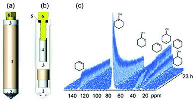 |
| | Fig. 21 Sketch high-temperature and high-pressure MAS rotor: (a) fully assembled rotor; and (b) showing the various components: (1) zirconia rotor sleeve, (2) ceramic insert made of materials such as Macor, (3) sample cell space, (4) thread, (5) O ring, (6) Torlon screw. The outside surface of the insert is fixed to the inner surface of the zirconia rotor sleeve by high-temperature glue. (c) Stacked plot of MAS-NMR spectra acquired as a function of time. (Reprinted with permission from ref. 131. Copyright © 2014 WILEY–VCH Verlag GmbH & Co. KGaA, Weinheim.) | |
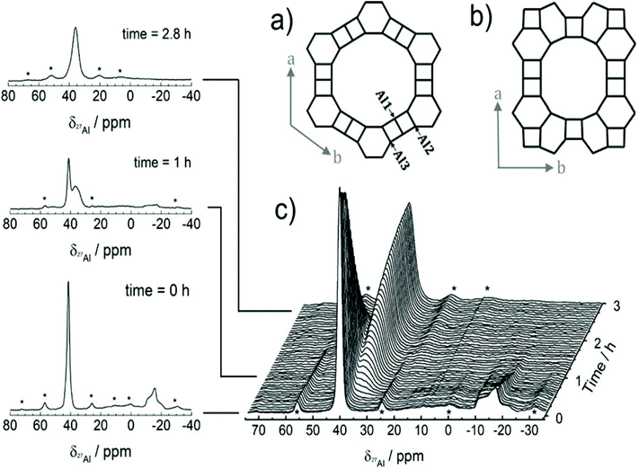 |
| | Fig. 22 (a) Structure of VPI-5 shown along c-direction, (b) structure of AlPO4-8 along c-direction. Alternating Al and P atoms are linked via oxygen atoms, the three crystallographically independent Al positions are marked in the figure. (c) In situ27Al MAS NMR spectra displaying the transformation of VPI-5 to AlPO4-8 (spinning with MAS rate of 2 kHz at 100 °C in a dry nitrogen flow). Asterisks denote spinning sidebands. (Reprinted with permission from ref. 119. Copyright © 2020, American Chemical Society.) | |
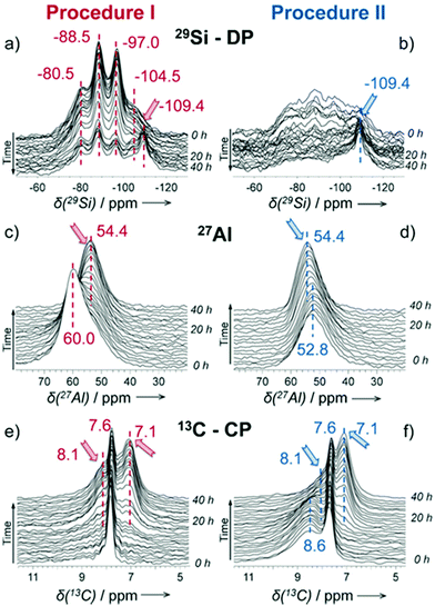 |
| | Fig. 23 Time-resolved 29Si MAS NMR spectra (a and b), 27Al MAS NMR (c and d), and 13C CP/MAS NMR (e and f) collected during zeolite BEA formation from the gels prepared according to different synthesis procedures I (a, c and e) and II (b, d and f). The arrows indicate the growing lines of zeolite BEA. The poor signal-to-noise ratio in the 29Si MAS NMR spectra (b) is due to the presence of rigid amorphous silica species leading to broad overlapping signals. (Reprinted with permission from ref. 129. © 2017 Wiley–VCH Verlag GmbH & Co. KGaA, Weinheim.) | |
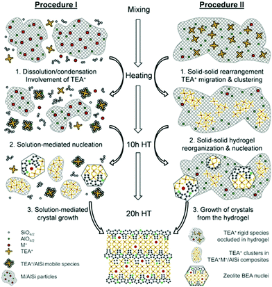 |
| | Fig. 24 Representation of the mechanism of zeolite BEA crystallization according to the different synthesis procedures I and II. (Reprinted with permission from ref. 129. © 2017 Wiley–VCH Verlag GmbH & Co. KGaA, Weinheim.) | |
X-ray absorption fine structure (XAFS)
XAFS, which can be divided into X-ray Absorption Near-Edge Structure (XANES) and Extended X-ray Absorption Fine Structure (EXAFS,) is a valuable tool for structural characterization. It requires high-energy synchrotron radiation with tunable wavelengths which corresponds to energies sufficiently high to eject electrons from specific electron orbitals of atoms. The intensity of the transmitted X-rays decreases due to this interaction causing a drop in the transmitted radiation intensity, a feature denoted as adsorption edge. Due to particle-wave duality, the released electron is further scattered by electrons from neighbouring atoms which causes interference effects containing information about the local environment around the specific element investigated. Recently published reviews provide a detailed overview of the theory and applications of XAFS, the details of which are beyond the scope of this article.132,133 As discussed before, the combination of adsorption experiments with structure-sensitive methods is mandatory for understanding the structure–property relationships of porous materials. Performing in situ XRD experiments during gas adsorption into the metal–organic framework DUT-8(Ni) provides direct insight into the gate opening mechanism, which is influenced by different probe molecules.16 The combination of adsorption and in situ EXAFS enabled for the first time monitoring of changes in the metal coordination, indicating a unique local deformation of the nickel-based paddle-wheel node. Kispersky et al. improved a plug-flow reactor for operando XAS studies of the selective catalytic reduction (SCR) of NOx by NH3 on different Cu/zeolites as an example reaction (Fig. 25).134 The studies were based on the fact that one potential limitation for in situ studies might be the reaction conditions in a plug-flow reactor. Conditions in an in situ XAS cell thus might not be identical. This of course can lead to erroneous conclusions about the structure and oxidation state of the active catalyst. The authors used vitreous carbon (glassy carbon) as a reactor material. Among others, the advantage of this material is that it is high temperature and pressure stable (up to 600 °C in air and 25 bar and 250 °C) and has a good X-ray transmittance. With the improved setup, operando XAS data and SCR reaction rates on Cu/zeolite catalysts could be measured simultaneously. Based on the operando experiments, an alternative reaction pathway via a redox mechanism was proposed. For the SCR reaction over Cu-zeolites, the amount of Cu(I) on the catalyst is determined by the relative rates of Cu(I) oxidation and Cu(II) reduction. The authors could show that the respective reaction rates depend on the zeolite support structure.134 Sun et al. explored Co single-atom sites embedded in hierarchically ordered porous N-doped carbon materials (CO-SAS-HOPNC) as catalysts for electrocatalytic hydrogen evolution reaction (OER) by in situ XAS.135 The specific surface area of the materials was 716 m2 g−1 with a total pore volume of 1.78 cm3 g−1. The high porosity of the material is important for providing sufficient space for the diffusion of reactants and products to and from the confined Co sites. In situ XAFS spectra were measured at the Co K-edge (7709 eV) in fluorescence mode at a synchrotron source. The scheme of the experimental setup is shown in Fig. 26. XANES and EXAFS spectra were evaluated to further probe the structure of Co species at the atomic level. Fig. 27a shows the Co K-edge ex situ XANES spectra of Co-SAS/HOPNC. The position of the absorption edge implies that the valence of Co atom is between Co0 and Co2+. EXAFS displays only one strong peak around 1.32 Å, which is assigned to the Co–N/C coordination within the first shell. The Co–Co peak at 2.17 Å is absent, which supports that the Co atoms are atomically dispersed (Fig. 27b). The in situ XAS measurements during HER were performed in 0.5 M H2SO4 at different potentials. The local atomic structure of Co-SAS/HOPNC remains stable during the catalytic H2 evolution reaction with no obvious changes in the in situ Co K-edge XANES and EXAFS spectra (Fig. 28). The studies are proof-of-principle that by the combination of XAS and electrochemical reactions highly dispersed isolated atomic Co–N4 active sites could be identified which remain stable during the reaction and show also a good catalytic performance.
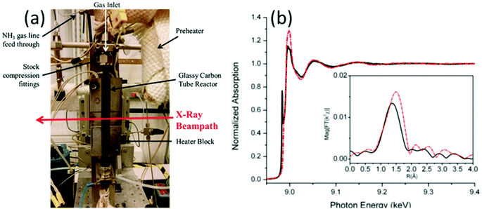 |
| | Fig. 25 (a) XAS reactor used for operando experiments (to show inside of the heater block, the front plate of the heater block was removed). (b) Normalized EXAFS spectra of Cu/ZSM-5 measured operando (red line) and under standard SCR conditions (black line). Inset shows Fourier transformed data. (Reprinted with permission from ref. 134. Copyright © 2012, The Royal Society of Chemistry.) | |
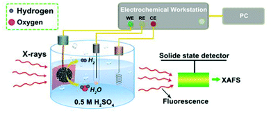 |
| | Fig. 26 Experimental setup used for the in situ XAS experiments. CE, RE, and WE represent counter, reference, and working electrodes. (Reprinted with permission from ref. 135. Copyright © 2018. Published under the PNAS license). | |
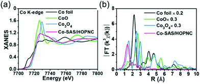 |
| | Fig. 27 (a) XANES and (b) FT-EXAFS curves of Co-SAS/HOPNC, CoO, Co3O4, and Co foil measured as references at the Co K edge. (Reprinted with permission from ref. 135. Copyright © 2018. Published under the PNAS license.) | |
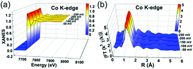 |
| | Fig. 28
In situ XAS experiments of Co-SAS/HOPNC: (a) XANES and (b) FT-EXAFS spectra measured at the Co K edge at different potentials. (Reprinted with permission from ref. 135. Copyright © 2018. Published under the PNAS license). | |
Vibrational spectroscopy
As already emphasized in the introduction, this review does not claim to discuss all methods available for the characterization of nanoporous materials. However, vibrational spectroscopy will be briefly discussed at this point but we also refer to recent comprehensive review articles on these methods.136,137 Raman and infrared (IR) spectroscopy provide information about the bulk structure of materials (especially defects) as well their surfaces. Both methods can probe adsorbed species, the nature of chemical bonding, reaction intermediates, and products. Vibrations in molecules or solids are generated by absorption (IR spectroscopy) or ineleastic scattering of photons (Raman spectroscopy). IR spectroscopy is widely used for the analysis of nanoporous materials because in situ sample cells can be implemented easily. Numerous papers on in situ spectroscopy monitoring adsorption processes under various gas atmospheres, pressures and temperatures have been published in the past.138–140 The detailed study of gas–solid interactions during catalytic reactions also became increasingly interesting. Shi et al. studied the steam reforming of methanol over oxide decorated nanoporous gold catalysts by diffuse reflectance infrared Fourier transform spectroscopy (DRIFT).141 First, the samples were calcined in situ at 300 °C for 90 min, followed by a cooling step at room temperature in flowing He. Next, CH3OH was injected and low-temperature FTIR experiments were performed between −35 °C and 20 °C. The low-temperature FTIR indicates that dehydrogenation of methanol to adsorbed methoxy and further to adsorbed formaldehyde and formate is the dominating reaction pathway for all tested catalysts. FTIR measurements under steady state conditions revealed that the activation of water and the formation of OHads is the key to the activity/selectivity of the catalysts.
Another interesting approach is the combination of diffuse reflection infrared Fourier transform spectroscopy and X-ray pair distribution function (PDF) analysis of host–guest systems.142 The analysis of total scattering data requires the consideration of all contributions to the scattering data which are caused by non-sample components. Therefore, a successful coupling of infrared and total X-ray scattering requires a careful experimental design. The authors performed PDF–IR measurements under variable temperature, pressure and gas atmospheres. By selecting DRIFTS optics with an appropriate geometry, total scattering and IR data could be simultaneously collected at a synchrotron source. The specifically designed setup ensured that the same sample volume was probed simultaneously by both techniques. For the proof-of-principle study, the dehydration of the Prussian blue analogue, [Mn3(Co(CN)6)2(H2O)6]·xH2O was studied in situ. The PDF data obtained during water desorption show changes in the coordination of the Mn cation and a temperature-dependent contraction of the structure. Complementary, the IR data reveal distinct features from the cyanide ligand and the guest molecules.
Both IR and Raman spectroscopy provide vibrational information on surface species (including adsorbed molecules) and solids. With Raman spectroscopy, CO2 and H2O can be analysed which are highly absorbing IR. In addition, glass and quartz are very weak Raman scatterers and can be therefore used for the design of in situ/operando cells. Raman spectroscopy is a powerful technique for characterizing carbon species under reaction conditions. However, fluorescence hinders the application of zeolite catalysts.143 The development of new laser sources for excitation ranging from the deep ultraviolet (UV) to the near-infrared (NIR) region, reduces effects such as background fluorescence and sample absorption efficiently.136 The use of NIR lasers with Fourier transform (FT) Raman spectrometers which use interferometers instead of monochromators circumvents fluorescence problems. In addition, the use of visible excitation sources in combination with Kerr-gated Raman spectroscopy was shown to be an effective technique to avoid fluorescence in zeolite samples.143 Kerr-gated spectrometers separate Raman signals and fluorescence on the temporal differences between the two processes.144 Lezcano-Gonzalez et al. studied the methanol-to-hydrocarbon conversion in zeolite SSZ-13 with a focus on the formation of hydrocarbon species during reaction at various stages.143 They combined a Kerr-gates Raman spectrometer with online gas analysis mass spectrometry. Above 290 °C polyenes were identified as crucial intermediates during the formation of polycyclic aromatic hydrocarbons. Based on the operando experiments, a direct correlation could be established between the formation of extended polyenes and catalyst deactivation. As first-principle molecular dynamics simulations show, confinement-induced effects limit the mobility of the large molecules which is responsible for catalyst deactivation.
Outlook
Nanoporous materials with their broad variety of chemical compositions, diversity of structures, different pore structures, and topologies will remain of great technical but also scientific importance in the future. Getting insights into, to name but a few, nucleation processes, adsorption mechanisms, or catalytic reactions requires the application of in situ or operando techniques. Analytical tools are available that provide information about the structure of nanoporous materials on different length scales from the atomic level to averaged crystal structures, from micropores to hierarchical pore systems. In the past, it was difficult to study disordered or nanosized materials and perform analytics under reaction conditions due to many technical problems. With the implementation of more and more sophisticated methods, high-energy probes, sensitive and fast detectors as well as powerful computers, we experienced a major technological leap in analytics. The elaboration of new experimental approaches continues. A new generation of powerful and brilliant synchrotron sources have been established over the last decade which provides higher spatial resolution. High intensity sources also enable the design of more complex sample environments. X-ray diffraction or scattering techniques benefit from detectors with very high sensitivity. Free-electron lasers (FEL) can help to follow chemical reactions with molecular resolution on an ultrafast timescale. With the improvement of novel lenses, X-ray microscopy is gaining resolution with a diameter of the focus spot of less than ten nanometers.145 Electron diffraction will go to the nanoscale and with this, crystal structures of nanomaterials become accessible. Great potential is seen in linking theoretical calculations and simulations with actual experiments. On the other hand, this requires intelligent management of the large amounts of data that are generated. Finally, a well-coordinated combination of different techniques can provide useful insights into structure–performance correlations, which are essential for understanding the properties of functional materials but also for designing tailor-made new nanoporous materials.
Author contributions
The authors contributed equally to this manuscript.
Conflicts of interest
There are no conflicts to declare.
Acknowledgements
We thank Wolfgang Schmidt (MPI Mülheim) for the critical reading of the manuscript. Open Access funding provided by the Max Planck Society.
References
- K. S. W. Sing, D. H. Everett, R. A. W. Haul, L. Moscou, R. A. Pierotti, J. Rouquerol and T. Siemieniewska, Reporting physisorption data for gas solid systems with special reference to the determination of surface-area and porosity (recommendations 1984), Pure Appl. Chem., 1985, 57(4), 603–619 CrossRef CAS.
- J. Rouquerol, G. Baron, R. Denoyel, H. Giesche, J. Groen, P. Klobes, P. Levitz, A. V. Neimark, S. Rigby, R. Skudas, K. Sing, M. Thommes and K. Unger, Liquid intrusion and alternative methods for the characterization of macroporous materials (IUPAC Technical Report), Pure Appl. Chem., 2011, 84(1), 107–136 CrossRef.
- S. Polarz and B. Smarsly, Nanoporous materials, J. Nanosci. Nanotechnol., 2002, 2(6), 581–612 CrossRef CAS PubMed.
-
Nanoporous Materials: Science and Engineering, ed. G. Q. Lu and X. S. Zhao, Series on Chemical Engineering, Imperial College Press, 2004, vol. 4 Search PubMed.
- D. Kerstens, B. Smeyers, J. Van Waeyenberg, Q. Zhang, J. Yu and B. F. Sels, State of the Art and Perspectives of Hierarchical Zeolites: Practical Overview of Synthesis Methods and Use in Catalysis, Adv. Mater., 2020, 32(44), 2004690 CrossRef CAS PubMed.
- Y. Yan, G. Chen, P. She, G. Zhong, W. Yan, B. Y. Guan and Y. Yamauchi, Mesoporous Nanoarchitectures for Electrochemical Energy Conversion and Storage, Adv. Mater., 2020, 32(44), 2004654 CrossRef CAS PubMed.
- T. A. Steriotis, K. L. Stefanopoulos, F. K. Katsaros, R. Gläser, A. C. Hannon and J. D. F. Ramsay, In situ neutron diffraction study of adsorbed carbon dioxide in a nanoporous material: Monitoring the adsorption mechanism and the structural characteristics of the confined phase, Phys. Rev. B: Condens. Matter Mater. Phys., 2008, 78(11), 115424 CrossRef.
- S. Gautam, T. Liu, G. Rother, N. Jalarvo, E. Mamontov, S. Welch, J. Sheets, M. Droege and D. R. Cole, Dynamics of Propane in Nanoporous Silica Aerogel: A Quasielastic Neutron Scattering Study, J. Phys. Chem. C, 2015, 119(32), 18188–18195 CrossRef CAS.
- G. Ferey, M. Haouas, T. Loiseau and F. Taulelle, Nanoporous Solids: How Do They Form? An In Situ Approach, Chem. Mater., 2014, 26(1), 299–309 CrossRef CAS.
- Z. Huang, E. S. Grape, J. Li, A. K. Inge and X. Zou, 3D electron diffraction as an important technique for structure elucidation of metal-organic frameworks and covalent organic frameworks, Coord. Chem. Rev., 2021, 427, 213583 CrossRef CAS.
- Z. Huang, T. Willhammar and X. Zou, Three-dimensional electron diffraction for porous crystalline materials: structural determination and beyond, Chem. Sci., 2021, 12(4), 1206–1219 RSC.
- M. Ge, X. Zou and Z. Huang, Three-Dimensional Electron Diffraction for Structural Analysis of Beam-Sensitive Metal-Organic Frameworks, Crystals, 2021, 11(3), 263 CrossRef CAS.
- W. Chaikittisilp, Y. Yamauchi and K. Ariga, Material Evolution with Nanotechnology, Nanoarchitectonics, and Materials Informatics: What will be the Next Paradigm Shift in Nanoporous Materials?, Adv. Mater., 2022, 34(7), 2107212 CrossRef CAS PubMed.
- B. T. W. Lo, L. Ye and S. C. E. Tsang, The Contribution of Synchrotron X-Ray Powder Diffraction to Modern Zeolite Applications: A Mini-review and Prospects, Chem, 2018, 4(8), 1778–1808 CAS.
- V. Bon, E. Brunner, A. Pöppl and S. Kaskel, Unraveling Structure and Dynamics in Porous Frameworks via Advanced In Situ Characterization Techniques, Adv. Funct. Mater., 2020, 30(41), 1907847 CrossRef CAS.
- V. Bon, N. Klein, I. Senkovska, A. Heerwig, J. Getzschmann, D. Wallacher, I. Zizak, M. Brzhezinskaya, U. Mueller and S. Kaskel, Exceptional adsorption-induced cluster and network deformation in the flexible metal-organic framework DUT-8(Ni) observed by in situ X-ray diffraction and EXAFS, Phys. Chem. Chem. Phys., 2015, 17(26), 17471–17479 RSC.
- S. Krause, V. Bon, I. Senkovska, U. Stoeck, D. Wallacher, D. M. Többens, S. Zander, R. S. Pillai, G. Maurin, F.-X. Coudert and S. Kaskel, A pressure-amplifying framework material with negative gas adsorption transitions, Nature, 2016, 532(7599), 348–352 CrossRef CAS PubMed.
- J. Goetze, I. Yarulina, J. Gascon, F. Kapteijn and B. M. Weckhuysen, Revealing Lattice Expansion of Small-Pore Zeolite Catalysts during the Methanol-to-Olefins Process Using Combined Operando X-ray Diffraction and UV–vis Spectroscopy, ACS Catal., 2018, 8(3), 2060–2070 CrossRef CAS PubMed.
- M. J. Van Vleet, T. Weng, X. Li and J. R. Schmidt, In Situ, Time-Resolved, and Mechanistic Studies of Metal–Organic Framework Nucleation and Growth, Chem. Rev., 2018, 118(7), 3681–3721 CrossRef CAS PubMed.
- P. Norby, In situ XRD as a tool to understanding zeolite crystallization, Curr. Opin. Colloid Interface Sci., 2006, 11(2), 118–125 CrossRef CAS.
- T. Friščić, I. Halasz, P. J. Beldon, A. M. Belenguer, F. Adams, S. A. J. Kimber, V. Honkimäki and R. E. Dinnebier, Real-time and in situ monitoring of mechanochemical milling reactions, Nat. Chem., 2013, 5(1), 66–73 CrossRef PubMed.
- I. Halasz, T. Friščić, S. A. Kimber, K. Užarević, A. Puškarić, C. Mottillo, P. Julien, V. Štrukil, V. Honkimäki and R. E. Dinnebier, Quantitative in situ and real-time monitoring of mechanochemical reactions, Faraday Discuss., 2014, 170, 203–221 RSC.
- I. Halasz, A. Puškarić, S. A. J. Kimber, P. J. Beldon, A. M. Belenguer, F. Adams, V. Honkimäki, R. E. Dinnebier, B. Patel, W. Jones, V. Štrukil and T. Friščić, Real–time in situ powder X–ray diffraction monitoring of mechanochemical synthesis of pharmaceutical cocrystals, Angew. Chem., 2013, 125(44), 11752–11755 CrossRef.
- S. Lukin, I. Lončarić, M. Tireli, T. Stolar, M. V. Blanco, P. Lazić, K. Užarević and I. Halasz, Experimental and Theoretical Study of Selectivity in Mechanochemical Cocrystallization of Nicotinamide with Anthranilic and Salicylic Acid, Cryst. Growth Des., 2018, 18(3), 1539–1547 CrossRef CAS.
- T. Stolar, L. Batzdorf, S. Lukin, D. Žilić, C. Motillo, T. Friščić, F. Emmerling, I. Halasz and K. Užarević, In situ monitoring of the mechanosynthesis of the archetypal metal–organic framework HKUST-1: Effect of liquid additives on the milling reactivity, Inorg. Chem., 2017, 56(11), 6599–6608 CrossRef CAS PubMed.
- K. Užarević, N. Ferdelji, T. Mrla, P. A. Julien, B. Halasz, T. Friščić and I. Halasz, Enthalpy vs. friction: heat flow modelling of unexpected temperature profiles in mechanochemistry of metal–organic frameworks, Chem. Sci., 2018, 9(9), 2525–2532 RSC.
- K. Užarević, I. Halasz and T. Friščić, Real-time and in situ monitoring of mechanochemical reactions: A new playground for all chemists, J. Phys. Chem. Lett., 2015, 6(20), 4129–4140 CrossRef PubMed.
- K. Uzarevic, V. Strukil, C. Mottillo, P. A. Julien, A. Puskaric, T. Friscic and I. Halasz, Exploring the effect of temperature on a mechanochemical reaction by in situ synchrotron powder X-ray diffraction, Cryst. Growth Des., 2016, 16(4), 2342–2347 CrossRef CAS.
- D. Gracin, V. Štrukil, T. Friščić, I. Halasz and K. Užarević, Laboratory Real-Time and In Situ Monitoring of Mechanochemical Milling Reactions by Raman Spectroscopy, Angew. Chem., Int. Ed., 2014, 53(24), 6193–6197 CrossRef CAS PubMed.
- M. Tireli, M. Juribašić Kulcsár, N. Cindro, D. Gracin, N. Biliškov, M. Borovina, M. Ćurić, I. Halasz and K. Užarević, Mechanochemical reactions studied by in situ Raman spectroscopy: base catalysis in liquid-assisted grinding, Chem. Commun., 2015, 51(38), 8058–8061 RSC.
- A. A. L. Michalchuk and F. Emmerling, Time-Resolved In Situ Monitoring of Mechanochemical Reactions, Angew. Chem., Int. Ed., 2022, e202117270 CAS.
- P. J. Beldon, L. Fábián, R. S. Stein, A. Thirumurugan, A. K. Cheetham and T. Friščić, Rapid Room-Temperature Synthesis of Zeolitic Imidazolate Frameworks by Using Mechanochemistry, Angew. Chem., Int. Ed., 2010, 49(50), 9640–9643 CrossRef CAS PubMed.
- J.-L. Do and T. Friščić, Mechanochemistry: A Force of Synthesis, ACS Cent. Sci., 2017, 3(1), 13–19 CrossRef CAS PubMed.
- T. Friščić, C. Mottillo and H. Titi, Mechanochemistry for synthesis, Angew. Chem., 2020, 132(3), 1030–1041 CrossRef.
- S. L. James, C. J. Adams, C. Bolm, D. Braga, P. Collier, T. Friščić, F. Grepioni, K. D. M. Harris, G. Hyett, W. Jones, A. Krebs, J. Mack, L. Maini, A. G. Orpen, I. P. Parkin, W. C. Shearouse, J. W. Steed and D. C. Waddell, Mechanochemistry: opportunities for new and cleaner synthesis, Chem. Soc. Rev., 2012, 41(1), 413–447 RSC.
- D. Tan and T. Friščić, Mechanochemistry for organic chemists: An update, Eur. J. Org. Chem., 2018, 18–33 CrossRef CAS.
- L. Batzdorf, F. Fischer, M. Wilke, K. J. Wenzel and F. Emmerling, Direct In Situ Investigation of Milling Reactions Using Combined X–ray Diffraction and Raman Spectroscopy, Angew. Chem., 2015, 127(6), 1819–1822 CrossRef.
- E. Stavitski, M. Goesten, J. Juan-Alcañiz, A. Martinez-Joaristi, P. Serra-Crespo, A. V. Petukhov, J. Gascon and F. Kapteijn, Kinetic Control of Metal–Organic Framework Crystallization Investigated by Time-Resolved In Situ X-Ray Scattering, Angew. Chem., Int. Ed., 2011, 50(41), 9624–9628 CrossRef CAS PubMed.
-
T. Egami and S. J. Billinge, Underneath the Bragg peaks: structural analysis of complex materials. 2012: Newnes.
- P. F. Peterson, D. Olds, M. T. McDonnell and K. Page, Illustrated formalisms for total scattering data: a guide for new practitioners, J. Appl. Crystallogr., 2021, 54(1), 317–332 CrossRef CAS PubMed.
- W. Friedrich, Eine neue Interferenzerscheinung bei Röntgenstrahlen, Phys. Z., 1913, 14, 317–319 CAS.
- P. Debye, Zerstreuung von Röntgenstrahlen, Ann. Phys., 1915, 351(6), 809–823 CrossRef.
- D. A. Keen, Total scattering and the pair distribution function in crystallography, Crystallogr. Rev., 2020, 26(3), 143–201 CrossRef.
- B. E. Warren, The Diffraction of X-Rays in Glass, Phys. Rev., 1934, 45(10), 657–661 CrossRef CAS.
- V. Petkov, P. Y. Zavalij, S. Lutta, M. S. Whittingham, V. Parvanov and S. Shastri, Structure beyond Bragg: Study of V2O5 nanotubes, Phys. Rev. B: Condens. Matter Mater. Phys., 2004, 69(8), 085410 CrossRef.
- V. Petkov, M. Gateshki, M. Niederberger and Y. Ren, Atomic-Scale Structure of Nanocrystalline
BaxSr1−-xTiO3 (x = 1, 0.5, 0) by X-ray Diffraction and the Atomic Pair Distribution Function Technique, Chem. Mater., 2006, 18(3), 814–821 CrossRef CAS.
- V. Petkov, Nanostructure by high-energy X-ray diffraction, Mater. Today, 2008, 11(11), 28–38 CrossRef CAS.
- S. K. Pradhan, Y. Mao, S. S. Wong, P. Chupas and V. Petkov, Atomic-Scale Structure of Nanosized Titania and Titanate: Particles, Wires, and Tubes, Chem. Mater., 2007, 19(25), 6180–6186 CrossRef CAS.
- S. J. L. Billinge and M. G. Kanatzidis, Beyond crystallography: the study of disorder, nanocrystallinity and crystallographically challenged materials with pair distribution functions, Chem. Commun., 2004, 7, 749–760 RSC.
- M. M. Martínez-Iñesta, I. Peral, T. Proffen and R. F. Lobo, A pair distribution function analysis of zeolite beta, Microporous Mesoporous Mater., 2005, 77(1), 55–66 CrossRef.
- T. Wakihara, S. Kohara, G. Sankar, S. Saito, M. Sanchez-Sanchez, A. R. Overweg, W. Fan, M. Ogura and T. Okubo, A new approach to the determination of atomic-architecture of amorphous zeolite precursors by high-energy X-ray diffraction technique, Phys. Chem. Chem. Phys., 2006, 8(2), 224–227 RSC.
- A. C. Forse, C. Merlet, P. K. Allan, E. K. Humphreys, J. M. Griffin, M. Aslan, M. Zeiger, V. Presser, Y. Gogotsi and C. P. Grey, New Insights into the Structure of Nanoporous Carbons from NMR, Raman, and Pair Distribution Function Analysis, Chem. Mater., 2015, 27(19), 6848–6857 CrossRef CAS.
- T. Iida, M. Shetty, K. Murugappan, Z. S. Wang, K. Ohara, T. Wakihara and Y. Roman-Leshkov, Encapsulation of Molybdenum Carbide Nanoclusters inside Zeolite Micropores Enables Synergistic Bifunctional Catalysis for Anisole Hydrodeoxygenation, ACS Catal., 2017, 7(12), 8147–8151 CrossRef CAS.
- G. N. Kalantzopoulos, F. Lundvall, S. Checchia, A. Lind, D. S. Wragg, H. Fjellvag and B. Arstad, In Situ Flow MAS NMR Spectroscopy and Synchrotron PDF Analyses of the Local Response of the Brønsted Acidic Site in SAPO-34 during Hydration at Elevated Temperatures, ChemPhysChem, 2018, 19(4), 519–528 CrossRef CAS PubMed.
- S. E. Henkelis, S. A. Morris, M. Mazur, P. S. Wheatley, L. N. McHugh and R. E. Morris, Monitoring the assembly-disassembly-organisation-reassembly process of germanosilicate UTL through in situ pair distribution function analysis, J. Mater. Chem. A, 2018, 6(35), 17011–17018 RSC.
- G. Sankar and W. Bras, Insights into the formation of microporous materials by in situ X-ray scattering techniques, Catal. Today, 2009, 145(3), 195–203 CrossRef CAS.
- H. Yamada, S. Tominaka, K. Ohara, Z. Liu, T. Okubo and T. Wakihara, Structural Evolution of Amorphous Precursors toward Crystalline Zeolites Visualized by an in Situ X-ray Pair Distribution Function Approach, J. Phys. Chem. C, 2019, 123(46), 28419–28426 CrossRef CAS.
- M. J. Hollamby, Practical applications of small-angle neutron scattering, Phys. Chem. Chem. Phys., 2013, 15(26), 10566–10579 RSC.
- C. Schlumberger and M. Thommes, Characterization of Hierarchically Ordered Porous Materials by Physisorption and Mercury Porosimetry—A Tutorial Review, Adv. Mater. Interfaces, 2021, 8(4), 2002181 CrossRef CAS.
- B. R. Pauw, Everything SAXS: small-angle scattering pattern collection and correction, J. Phys.: Condens. Matter, 2013, 25(38), 383201 CrossRef PubMed.
- V. K. Peterson and C. M. Papadakis, Functional materials analysis using in situ and in operando X-ray and neutron scattering, IUCrJ, 2015, 2(Pt 2), 292–304 CrossRef CAS PubMed.
- J. Feng, M. Kriechbaum and L. Liu, In situ capabilities of Small Angle X-ray Scattering, Nanotechnol. Rev., 2019, 8(1), 352–369 CAS.
- C. J. Gommes, S. Jaksch and H. Frielinghaus, Small-angle scattering
for beginners, J. Appl. Crystallogr., 2021, 54, 1832–1843 CrossRef CAS PubMed.
- D. Stoeckel, D. Wallacher, G. A. Zickler, M. Thommes and B. M. Smarsly, Elucidating the Sorption Mechanism of Dibromomethane in Disordered Mesoporous Silica Adsorbents, Langmuir, 2015, 31(23), 6332–6342 CrossRef CAS PubMed.
- W. Schmidt and H. Amenitsch, High Dynamics of Vapor Adsorption in Ordered Mesoporous Carbon CMK-5: A Small Angle X-ray Scattering Study, J. Phys. Chem. C, 2020, 124(39), 21418–21425 CrossRef CAS.
- S. J. Richardson, M. R. Burton, X. Luo, P. A. Staniec, I. S. Nandhakumar, N. J. Terrill, J. M. Elliott and A. M. Squires, Watching mesoporous metal films grow during templated electrodeposition with in situ SAXS, Nanoscale, 2017, 9(29), 10227–10232 RSC.
- E. A. C. Panduro, H. Granlund, M. Sztucki, O. Konovalov, D. W. Breiby and A. Gibaud, Using Three-Dimensional 3D Grazing-Incidence Small-Angle X-ray Scattering (GISAXS) Analysis To Probe Pore Deformation in Mesoporous Silica Films, ACS Appl. Mater. Interfaces, 2014, 6(4), 2686–2691 CrossRef CAS PubMed.
- A. Alvarez-Fernandez, B. Reid, M. J. Fornerod, A. Taylor, G. Divitini and S. Guldin, Structural Characterization of Mesoporous Thin Film Architectures: A Tutorial Overview, ACS Appl. Mater. Interfaces, 2020, 12(5), 5195–5208 CrossRef CAS PubMed.
- S. Boukhalfa, L. He, Y. B. Melnichenko and G. Yushin, Small-Angle Neutron Scattering for In Situ Probing of Ion Adsorption Inside Micropores, Angew. Chem., Int. Ed., 2013, 52(17), 4618–4622 CrossRef CAS PubMed.
-
L. Keshavarz, M. R. Ghaani, O. Saremi, N. J. English, Characterization of Nanoporous Materials, in Advanced Functional Porous Materials: From Macro to Nano Scale Lengths, ed. A. Uthaman, S. Thomas, T. Li and H. Maria, Engineering Materials, Springer, 2021, pp. 319–353 Search PubMed.
- C. Zhang, K. L. Firestein, J. F. S. Fernando, D. Siriwardena, J. E. von Treifeldt and D. Golberg, Recent Progress of In Situ Transmission Electron Microscopy for Energy Materials, Adv. Mater., 2020, 32(18), 1904094 CrossRef CAS PubMed.
- Z. Fan, L. Zhang, D. Baumann, L. Mei, Y. Yao, X. Duan, Y. Shi, J. Huang, Y. Huang and X. Duan, In Situ Transmission Electron Microscopy for Energy Materials and Devices, Adv. Mater., 2019, 31(33), 1900608 CrossRef PubMed.
- Z.-P. Wu, H. Zhang, C. Chen, G. Li and Y. Han, Applications of in situ electron microscopy in oxygen electrocatalysis, Microstructures, 2022, 2(1), 2022002 Search PubMed.
- Q. Chen, C. Dwyer, G. Sheng, C. Zhu, X. Li, C. Zheng and Y. Zhu, Imaging Beam-Sensitive Materials by Electron Microscopy, Adv. Mater., 2020, 32(16), 1907619 CrossRef CAS PubMed.
- J. Zhang, N. Cheng and B. Ge, Characterization of metal-organic frameworks by transmission electron microscopy, Adv. Phys.: X, 2022, 7(1), 2046157 Search PubMed.
- A. M. Jasim, X. He, Y. Xing, T. A. White and M. J. Young, Cryo-ePDF: Overcoming Electron Beam Damage to Study the Local Atomic Structure of Amorphous ALD Aluminum Oxide Thin Films within a TEM, ACS Omega, 2021, 6(13), 8986–9000 CrossRef CAS PubMed.
- Y. Lin, M. Zhou, X. Tai, H. Li, X. Han and J. Yu, Analytical transmission electron microscopy for emerging advanced materials, Matter, 2021, 4(7), 2309–2339 CrossRef CAS.
- M. Juneau, R. Liu, Y. Peng, A. Malge, Z. Ma and M. D. Porosoff, Characterization of Metal-zeolite Composite Catalysts: Determining the Environment of the Active Phase, ChemCatChem, 2020, 12(7), 1826–1852 CrossRef CAS.
- O. Regev, Y. Cohen, E. Kehat and Y. Talmon, Precursors of the zeolite ZSM-5 imaged by Cryo-TEM and by SAXS, Zeolites, 1994, 14, 314–319 CrossRef CAS.
- T. Li, H. Wu, J. Ihli, Z. Ma, F. Krumeich, P. H. H. Bomans, N. A. J. M. Sommerdijk, H. Friedrich, J. P. Patterson and J. A. van Bokhoven, Cryo-TEM and electron tomography reveal leaching-induced pore formation in ZSM-5 zeolite, J. Mater. Chem. A, 2019, 7(4), 1442–1446 RSC.
- J. P. Patterson, P. Abellan, M. S. Denny, C. Park, N. D. Browning, S. M. Cohen, J. E. Evans and N. C. Gianneschi, Observing the Growth of Metal–Organic Frameworks by in Situ Liquid Cell Transmission Electron Microscopy, J. Am. Chem. Soc., 2015, 137(23), 7322–7328 CrossRef CAS PubMed.
- Y. Oshima, T. Tsuda, S. Kuwabata, H. Yasuda and K. Takayanagi, Development of an electrochemical cell for in situ transmission electron microscopy observation, Microscopy, 2014, 63(6), 481–486 CrossRef CAS PubMed.
- Y. Wu and N. Liu, Visualizing Battery Reactions and Processes by Using In Situ and In Operando Microscopies, Chem, 2018, 4(3), 438–465 CAS.
- M. L. Taheri, E. A. Stach, I. Arslan, P. A. Crozier, B. C. Kabius, T. LaGrange, A. M. Minor, S. Takeda, M. Tanase, J. B. Wagner and R. Sharma, Current status and future directions for in situ transmission electron microscopy, Ultramicroscopy, 2016, 170, 86–95 CrossRef CAS PubMed.
- L. R. Parent, C. H. Pham, J. P. Patterson, M. S. Denny, S. M. Cohen, N. C. Gianneschi and F. Paesani, Pore Breathing of Metal–Organic Frameworks by Environmental Transmission Electron Microscopy, J. Am. Chem. Soc., 2017, 139(40), 13973–13976 CrossRef CAS PubMed.
- T. Gruene, J. J. Holstein, G. H. Clever and B. Keppler, Establishing electron diffraction in chemical crystallography, Nat. Rev. Chem., 2021, 5(9), 660–668 CrossRef CAS.
- U. Kolb, T. Gorelik, C. Kübel, M. T. Otten and D. Hubert, Towards automated diffraction tomography: Part I—Data acquisition, Ultramicroscopy, 2007, 107(6), 507–513 CrossRef CAS PubMed.
- U. Kolb, T. Gorelik and M. T. Otten, Towards automated diffraction tomography. Part II—Cell parameter determination, Ultramicroscopy, 2008, 108(8), 763–772 CrossRef CAS PubMed.
- U. Kolb, E. Mugnaioli and T. E. Gorelik, Automated electron diffraction tomography – a new tool for nano crystal structure analysis, Cryst. Res. Technol., 2011, 46(6), 542–554 CrossRef CAS.
- E. Mugnaioli, T. Gorelik and U. Kolb, “Ab initio” structure solution from electron diffraction data obtained by a combination of automated diffraction tomography and precession technique, Ultramicroscopy, 2009, 109(6), 758–765 CrossRef CAS PubMed.
- T. E. Weirich, R. Ramlau, A. Simon, S. Hovmöller and X. Zou, A crystal structure determined with 0.02 Å accuracy by electron microscopy, Nature, 1996, 382(6587), 144–146 CrossRef CAS.
- T. E. Weirich, X. Zou, R. Ramlau, A. Simon, G. L. Cascarano, C. Giacovazzo and S. Hovmoller, Structures of nanometre-size crystals determined from selected-area electron diffraction data, Acta Crystallogr., Sect. A: Found. Crystallogr., 2000, 56(1), 29–35 CrossRef CAS PubMed.
- M. O. Cichocka, J. Angstrom, B. Wang, X. Zou and S. Smeets, High-throughput continuous rotation electron diffraction data acquisition via software automation, J. Appl. Crystallogr., 2018, 51(6), 1652–1661 CrossRef CAS PubMed.
- B. Wang, X. Zou and S. Smeets, Automated serial rotation electron diffraction combined with cluster analysis: an efficient multi-crystal workflow for structure determination, IUCrJ, 2019, 6(5), 854–867 CrossRef CAS PubMed.
- E. Mugnaioli, A. E. Lanza, G. Bortolozzi, L. Righi, M. Merlini, V. Cappello, L. Marini, A. Athanassiou and M. Gemmi, Electron Diffraction on Flash-Frozen Cowlesite Reveals the Structure of the First Two-Dimensional Natural Zeolite, ACS Cent. Sci., 2020, 6(9), 1578–1586 CrossRef CAS PubMed.
- T. Gorelik and U. Kolb, The pair distribution function from electron diffraction data, Int. Tables Crystallogr., 2019, 113–114 Search PubMed.
- T. E. Gorelik, R. Neder, M. W. Terban, Z. Lee, X. Mu, C. Jung, T. Jacob and U. Kaiser, Towards quantitative treatment of electron pair distribution function, Acta Crystallogr., Sect. B: Struct. Sci., Cryst. Eng. Mater., 2019, 75(4), 532–549 CrossRef CAS PubMed.
- J. B. Souza Junior, G. R. Schleder, J. Bettini, I. C. Nogueira, A. Fazzio and E. R. Leite, Pair Distribution Function Obtained from Electron Diffraction: An Advanced Real-Space Structural Characterization Tool, Matter, 2021, 4(2), 441–460 CrossRef CAS.
- C. Zhao and Y. Qiao, Characterization of nanoporous structures: from three dimensions to two dimensions, Nanoscale, 2016, 8(40), 17658–17664 RSC.
- J. Qu and X. Liu, Recent Advances on SEM-Based In Situ Multiphysical Characterization of Nanomaterials, Scanning, 2021, 2021, 4426254 CrossRef PubMed.
- N. Nan and J. Wang, FIB-SEM Three-Dimensional Tomography for Characterization of Carbon-Based Materials, Adv. Mater. Sci. Eng., 2019, 2019, 8680715 Search PubMed.
- K. Bae, J. W. Kim, J.-w. Son, T. Lee, S. Kang, F. B. Prinz and J. H. Shim, 3D Evaluation of Porous Zeolite Absorbents Using FIB-SEM Tomography, Int. J. Precis. Eng. Manuf.- Green Technol., 2018, 5(2), 195–199 CrossRef.
- F. Meirer and B. M. Weckhuysen, Spatial and temporal exploration of heterogeneous catalysts with synchrotron radiation, Nat. Rev. Mater., 2018, 3(9), 324–340 CrossRef.
- T. M. M. Heenan, C. Tan, J. Hack, D. J. L. Brett and P. R. Shearing, Developments in X-ray tomography characterization for electrochemical devices, Mater. Today, 2019, 31, 69–85 CrossRef CAS.
-
D. Matras, J. Pritchard, A. Vamvakeros, S. D. M. Jacques and A. M. Beale, Tomography in Catalyst Design, in Heterogeneous Catalysts, Advanced Design, Characterization and Applications, ed. W. Y. Teoh, A. Urakawa, Y. H. Ng and P. Sit, Wiley-VCH, 2021 Search PubMed.
- D. S. Wragg, G. N. Kalantzopoulos, D. K. Pappas, I. Pinilla-Herrero, D. Rojo-Gama, E. Redekop, M. Di Michiel, P. Beato, L. F. Lundegaard and S. Svelle, Mapping the coke formation within a zeolite catalyst extrudate in space and time by operando computed X-ray diffraction tomography, J. Catal., 2021, 401, 1–6 CrossRef CAS.
- Z. Ji, T. Li and O. M. Yaghi, Sequencing of metals in multivariate metal-organic frameworks, Science, 2020, 369(6504), 674–680 CrossRef CAS PubMed.
- B. Pfeiffer, T. Erichsen, E. Epler, C. A. Volkert, P. Trompenaars and C. Nowak, Characterization of Nanoporous Materials with Atom Probe Tomography, Microsc. Microanal., 2015, 21(3), 557–563 CrossRef CAS PubMed.
- J. E. Schmidt, L. Peng, J. D. Poplawsky and B. M. Weckhuysen, Nanoscale Chemical Imaging of Zeolites Using Atom Probe Tomography, Angew. Chem., Int. Ed., 2018, 57(33), 10422–10435 CrossRef CAS PubMed.
- C. Barroo, A. J. Akey and D. C. Bell, Atom Probe Tomography for Catalysis Applications: A Review, Appl. Sci., 2019, 9(13), 2721–2756 CrossRef CAS.
- B. Gault, A. Chiaramonti, O. Cojocaru-Mirédin, P. Stender, R. Dubosq, C. Freysoldt, S. K. Makineni, T. Li, M. Moody and J. M. Cairney, Atom probe tomography, Nat. Rev. Methods Primers, 2021, 1, 1–30 CrossRef.
- S. H. van Vreeswijk, M. Monai, R. Oord, J. E. Schmidt, E. T. C. Vogt, J. D. Poplawsky and B. M. Weckhuysen, Nano-scale insights regarding coke formation in zeolite SSZ-13 subject to the methanol-to-hydrocarbons reaction, Catal. Sci. Technol., 2022, 12(4), 1220–1228 RSC.
- J. E. Schmidt, X. Ye, I. K. van Ravenhorst, R. Oord, D. A. Shapiro, Y.-S. Yu, S. R. Bare, F. Meirer, J. D. Poplawsky and B. M. Weckhuysen, Probing the Location and Speciation of Elements in Zeolites with Correlated Atom Probe Tomography and Scanning Transmission X-Ray Microscopy, ChemCatChem, 2019, 11(1), 488–494 CrossRef CAS PubMed.
- X. Shi, N. Burdet, B. Chen, G. Xiong, R. Streubel, R. Harder and I. K. Robinson, X-ray ptychography on low-dimensional hard-condensed matter materials, Appl. Phys. Rev., 2019, 6(1), 011306 Search PubMed.
- K. Shimomura, M. Hirose, T. Higashino and Y. Takahashi, Three-dimensional iterative multislice reconstruction for ptychographic X-ray computed tomography, Opt. Express, 2018, 26(24), 31199–31208 CrossRef CAS PubMed.
- T. Weissenberger, R. Leonhardt, B. A. Zubiri, M. Pitínová-Štekrová, T. L. Sheppard, B. Reiprich, J. Bauer, R. Dotzel, M. Kahnt, A. Schropp, C. G. Schroer, J.-D. Grunwaldt, J. L. Casci, J. Čejka, E. Spiecker and W. Schwieger, Synthesis and Characterisation of Hierarchically Structured Titanium Silicalite-1 Zeolites with Large Intracrystalline Macropores, Chem. – Eur. J., 2019, 25(63), 14430–14440 CrossRef CAS PubMed.
- M. Kahnt, J. Becher, D. Brückner, Y. Fam, T. Sheppard, T. Weissenberger, F. Wittwer, J.-D. Grunwaldt, W. Schwieger and C. G. Schroer, Coupled ptychography and tomography algorithm improves reconstruction of experimental data, Optica, 2019, 6(10), 1282–1289 CrossRef CAS.
- T. Li, J. Ihli, Z. Ma, F. Krumeich and J. A. van Bokhoven, Composition and Structure Dependent Mesopore/Macropore Formation in Zeolites by Desilication, J. Phys. Chem. C, 2019, 123(14), 8793–8801 CrossRef CAS.
- C. Paula, D. Wisser, M. Rangus, W. Schwieger, M. Hovestadt, M. Kriesten, K. Vanatalu, A. Oss, M. L. Org, A. Samoson and M. Hartmann, Phase Transformations in Porous Materials Studied by In Situ Solid-State NMR Spectroscopy and In Situ X-ray Diffraction, J. Phys. Chem. C, 2020, 124(35), 19136–19145 CrossRef CAS.
- I. I. Ivanova and Y. G. Kolyagin, Impact of in situ MAS NMR techniques to the understanding of the mechanisms of zeolite catalyzed reactions, Chem. Soc. Rev., 2010, 39(12), 5018–5050 RSC.
- A. A. Gabrienko, S. S. Arzumanov, D. Freude and A. G. Stepanov, Propane Aromatization on Zn-Modified Zeolite BEA Studied by Solid-State NMR in Situ, J. Phys. Chem. C, 2010, 114(29), 12681–12688 CrossRef CAS.
- M. Hunger, In situ NMR spectroscopy in heterogeneous catalysis, Catal. Today, 2004, 97(1), 3–12 CrossRef CAS.
- L. Qi, R. Alamillo, W. A. Elliott, A. Andersen, D. W. Hoyt, E. D. Walter, K. S. Han, N. M. Washton, R. M. Rioux, J. A. Dumesic and S. L. Scott, Operando Solid-State NMR Observation of Solvent-Mediated Adsorption-Reaction
of Carbohydrates in Zeolites, ACS Catal., 2017, 7(5), 3489–3500 CrossRef CAS.
- I. I. Ivanova and Y. G. Kolyagin, Application of Multinuclear MAS NMR for the in situ Monitoring of Hydrothermal Synthesis of Zeolites, Chem. – Eur. J., 2021, 27(57), 14143–14167 CrossRef CAS PubMed.
- J. Shi, M. W. Anderson and S. W. Carr, Direct Observation of Zeolite A Synthesis by in Situ Solid-State NMR, Chem. Mater., 1996, 8(2), 369–375 CrossRef CAS.
- F. Taulelle, M. Haouas, C. Gerardin, C. Estournes, T. Loiseau and G. Ferey, NMR of microporous compounds: From in situ reactions to solid paving, Colloids Surf., A, 1999, 158(1), 299–311 CrossRef CAS.
- C. In-Gérardin, M. In and F. Taulelle, In situ NMR measurements under hydrothermal conditions: study of the formation of polymeric Al hydrolysis species, J. Chim. Phys., 1995, 92, 1877–1880 CrossRef.
- M. Haouas, C. Gérardin, F. Taulelle, C. Estournes, T. Loiseau and G. Ferey, In situ NMR study of hydrothermal synthesis of a template-mediated microporous aluminophosphate material: AlPO4-CJ2, J. Chim. Phys., 1998, 95(2), 302–309 CrossRef CAS.
- I. I. Ivanova, Y. G. Kolyagin, I. A. Kasyanov, A. V. Yakimov, T. O. Bok and D. N. Zarubin, Time-Resolved In Situ MAS NMR Monitoring of the Nucleation and Growth of Zeolite BEA Catalysts under Hydrothermal Conditions, Angew. Chem., Int. Ed., 2017, 56(48), 15344–15347 CrossRef CAS PubMed.
- J. Z. Hu, M. Y. Hu, Z. Zhao, S. Xu, A. Vjunov, H. Shi, D. M. Camaioni, C. H. F. Peden and J. A. Lercher, Sealed rotors for in situ high temperature high pressure MAS NMR, Chem. Commun., 2015, 51(70), 13458–13461 RSC.
- A. Vjunov, M. Y. Hu, J. Feng, D. M. Camaioni, D. Mei, J. Z. Hu, C. Zhao and J. A. Lercher, Following Solid-Acid-Catalyzed Reactions by MAS NMR Spectroscopy in Liquid Phase—Zeolite-Catalyzed Conversion of Cyclohexanol in Water, Angew. Chem., Int. Ed., 2014, 53(2), 479–482 CrossRef CAS PubMed.
- W. Grunert and K. Klementiev, X-ray absorption spectroscopy principles and practical use in materials analysis, Phys. Sci. Rev., 2020, 5(4), 1–35 Search PubMed.
- S. H. van Vreeswijk and B. M. Weckhuysen, Emerging Analytical Methods to Characterize Zeolite-Based Materials, Natl. Sci. Rev., 2022, nwac047 CrossRef.
- V. F. Kispersky, A. J. Kropf, F. H. Ribeiro and J. T. Miller, Low absorption vitreous carbon reactors for operando XAS: a case study on Cu/Zeolites for selective catalytic reduction of NOx by NH3, Phys. Chem. Chem. Phys., 2012, 14(7), 2229–2238 RSC.
- T. Sun, S. Zhao, W. Chen, D. Zhai, J. Dong, Y. Wang, S. Zhang, A. Han, L. Gu, R. Yu, X. Wen, H. Ren, L. Xu, C. Chen, Q. Peng, D. Wang and Y. Li, Single-atomic cobalt sites embedded in hierarchically ordered porous nitrogen-doped carbon as a superior bifunctional electrocatalyst, Proc. Natl. Acad. Sci. U. S. A., 2018, 115(50), 12692–12697 CrossRef CAS PubMed.
- C. Hess, New advances in using Raman spectroscopy for the characterization of catalysts and catalytic reactions, Chem. Soc. Rev., 2021, 50(5), 3519–3564 RSC.
- E. Stavitski and B. M. Weckhuysen, Infrared and Raman imaging of heterogeneous catalysts, Chem. Soc. Rev., 2010, 39(12), 4615–4625 RSC.
- Y. Yue, J. A. Rabone, H. Liu, S. M. Mahurin, M.-R. Li, H. Wang, Z. Lu, B. Chen, J. Wang, Y. Fang and S. Dai, A Flexible Metal–Organic Framework: Guest Molecules Controlled Dynamic Gas Adsorption, J. Phys. Chem. C, 2015, 119(17), 9442–9449 CrossRef CAS.
- J. Marreiros, R. de Oliveira-Silva, P. Iacomi, P. L. Llewellyn, R. Ameloot and D. Sakellariou, Benchtop In Situ Measurement of Full Adsorption Isotherms by NMR, J. Am. Chem. Soc., 2021, 143(22), 8249–8254 CrossRef CAS PubMed.
- N. L. Drenchev, K. K. Chakarova, O. V. Lagunov, M. Y. Mihaylov, E. Z. Ivanova, I. Strauss and K. I. Hadjiivanov, In situ FTIR Spectroscopy as a Tool for Investigation of Gas/Solid Interaction: Water-Enhanced CO2 Adsorption in UiO-66 Metal-Organic Framework, JoVE, 2020,(156), e60285 CAS.
- J. Shi, C. Mahr, M. M. Murshed, T. M. Gesing, A. Rosenauer, M. Bäumer and A. Wittstock, Steam reforming of methanol over oxide decorated nanoporous gold catalysts: a combined in situ FTIR and flow reactor study, Phys. Chem. Chem. Phys., 2017, 19(13), 8880–8888 RSC.
- K. A. Beyer, H. Zhao, O. J. Borkiewicz, M. A. Newton, P. J. Chupas and K. W. Chapman, Simultaneous diffuse reflection infrared spectroscopy and X-ray pair distribution function measurements, J. Appl. Crystallogr., 2014, 47(1), 95–101 CrossRef CAS.
- I. Lezcano-Gonzalez, E. Campbell, A. E. J. Hoffman, M. Bocus, I. V. Sazanovich, M. Towrie, M. Agote-Aran, E. K. Gibson, A. Greenaway, K. De Wispelaere, V. Van Speybroeck and A. M. Beale, Insight into the effects of confined hydrocarbon species on the lifetime of methanol conversion catalysts, Nat. Mater., 2020, 19(10), 1081–1087 CrossRef CAS PubMed.
- P. Matousek, M. Towrie, A. Stanley and A. W. Parker, Efficient Rejection of Fluorescence from Raman Spectra Using Picosecond Kerr Gating, Appl. Spectrosc., 1999, 53(12), 1485–1489 CrossRef CAS.
- S. Bajt, M. Prasciolu, H. Fleckenstein, M. Domaracký, H. N. Chapman, A. J. Morgan, O. Yefanov, M. Messerschmidt, Y. Du, K. T. Murray, V. Mariani, M. Kuhn, S. Aplin, K. Pande, P. Villanueva-Perez, K. Stachnik, J. P. J. Chen, A. Andrejczuk, A. Meents, A. Burkhardt, D. Pennicard, X. Huang, H. Yan, E. Nazaretski, Y. S. Chu and C. E. Hamm, X-ray focusing with efficient high-NA multilayer Laue lenses, Light: Sci. Appl., 2018, 7(3), 17162–17162 CrossRef CAS PubMed.
|
| This journal is © the Partner Organisations 2022 |
 Open Access Article
 *
*


