
 Open Access Article
 This Open Access Article is licensed under a Creative Commons Attribution-Non Commercial 3.0 Unported Licence
Morphology and topology assessment in hierarchical zeolite materials: adsorption hysteresis, scanning behavior, and domain theory†
Céline
Pagis
 ab,
David
Laprune
a,
Lucian
Roiban
c,
Thierry
Epicier
ac,
Cécile
Daniel
a,
Alain
Tuel
a,
David
Farrusseng
*a and
Benoit
Coasne
*d
ab,
David
Laprune
a,
Lucian
Roiban
c,
Thierry
Epicier
ac,
Cécile
Daniel
a,
Alain
Tuel
a,
David
Farrusseng
*a and
Benoit
Coasne
*d
aUniversité de Lyon, Université Claude Bernard Lyon 1, CNRS, IRCELYON-UMR 5256, 69626 Villeurbanne Cedex, France. E-mail: david.farrusseng@ircelyon.univ-lyon1.fr
bIFP Energies Nouvelles, Rond-Point de l'échangeur de Solaize, BP3, 69360 Solaize, France
cUniv Lyon, INSA Lyon, Université Claude Bernard Lyon 1, CNRS, MATEIS, UMR5510, 69621 Villeurbanne, France
dLaboratoire Interdisciplinaire de Physique, CNRS and Université Grenoble Alpes - UMR 5588, 38000 Grenoble, France. E-mail: benoit.coasne@univ-grenoble-alpes.fr
First published on 26th April 2022
Abstract
Using a prototypical family of hierarchical zeolites, we show how adsorption-based characterization can be extended to provide morphological and topological assessment beyond state-of-the-art tools. The well-controlled materials under study consist of submicron-sized zeolite crystals (silicalite-1) that exhibit large nanoporous cavities in addition to their intrinsic microporosity. Such zeolites nanoboxes can be prepared with a single large cavity, with several independent cavities or with several interconnected cavities depending on synthesis conditions. It is shown that analysis of the adsorption/desorption branches using the Derjaguin model allows determining the cavity size distributions in these materials but also the fraction of pores directly connected to the external surface for each cavity size. Moreover, using the independent domain theory, we illustrate how scanning the capillary hysteresis provides a means to determine whether pores behave independently from each other or are connected to each other. All our findings are found to be consistent with additional electron microscopy data including electron tomography data.
1. Introduction
Owing to their large accessible surface area and confining properties, porous materials are central to many practical applications such as heterogeneous catalysis, adsorption, filtration, chromatography, and gas/phase separation.1–4 In particular, the use of porous materials is a key aspect of many technologies relevant to energy storage/conversion, environment protection/depollution, materials science, etc. Among available porous solids, hierarchical porous materials, which are multiscale solids combining different porosity scales (microporosity <2 nm, mesoporosity in the range 2–50 nm, and macroporosity >50 nm), are at the heart of intensive research as they allow overcoming important technological barriers.5,6 These multiscale porous solids possess a large specific surface area together with large pores ensuring high permeability so that they lead to very efficient catalytic, adsorption, and separation properties. As a result, efficient characterization techniques are required in order to develop rational synthesis strategies for such hierarchical media.Many characterization tools have been developed to assess the surface and volume properties of porous materials; such tools include but are not limited to imaging techniques at different scales (such as transmission/scanning electron microscopy,7–10 focused ion beam scanning electron microscopy and tomography experiments11,12), spectroscopic tools such as infrared/Raman spectroscopy,13,14 both small and wide angle X-ray and neutron scattering or diffraction,15–19 and thermal analysis (differential scanning calorimetry, differential thermal analysis).11,20 In addition to these techniques, adsorption-based methods in which the adsorption or intrusion of a fluid is used to probe the surface and porosity of porous materials are widely used as they allow fine characterization in a non-destructive fashion.21–23 Such methods include the adsorption of a simple fluid at low temperature such as N2 or Ar (gas volumetry or gravimetry), adsorption of water at room temperature or at low temperature (Nuclear Magnetic Resonance cryoporometry/thermoporometry),24,25 density assessment using a non-adsorbing fluid (He pycnometry), or invasion by a non-wetting fluid (Hg porosimetry).23 Among characterization based on wetting fluids, N2, Ar, and water adsorption techniques are particularly useful as they allow probing at the same time the surface chemistry, porosity/porous volume, and cavity size of any porous material (ranging from simple/independent pores with uniform or non-monodisperse sizes to strongly disordered porous solids with pores having a complex morphology/topology).
In addition to such simple yet robust characterization tools, detailed analysis of capillary condensation hystereses observed upon adsorption/desorption cycles (shape of the hysteresis loop and its scanning behavior) provides very important information regarding the morphology and topology of the porous network in a given material.26–29 On the one hand, symmetrical hystereses loops – i.e. with parallel, superimposable adsorption and desorption branches – can be taken as the signature of porous materials with independent pores (in this context, independent pores refer to pores that fill or empty regardless of whether their neighbors are filled or empty). On the other hand, asymmetrical hystereses are indicative of disordered porous materials where desorption is controlled by neck effects (large pores being isolated from the gas phase through smaller cavities).21,22,30 As for the scanning behavior within the capillary condensation hysteresis, in the frame of the independent domain theory by Everett,31 the way an ascending (descending) scanning curve meets the main adsorption (desorption) branch can be used to assess the pore connectivity within a porous material.
In the present paper, an ideal yet representative family of hierarchical porous materials is used to show how adsorption-based characterization – beyond state-of-the-art techniques – allows determining quantitatively the pore connectivity/topology in such complex, multiscale solids. The hierarchical porous materials considered here consist of hollow zeolite boxes having dimensions ranging from tens to hundreds of nanometers (the zeolite structure is that of silicalite-1).32–35 Depending on the chemical procedure used, such silicalite-1 nanoboxes exhibit in addition to the zeolitic (i.e. microporous) cavities another porosity which consists of (1) a single large cavity (100–200 nm), (2) several large independent cavities (0–150 nm), or (3) several large connected cavities (0–150 nm). By comparing these materials with their parent solid (i.e. the same zeolite boxes without additional porosity), we show that key information regarding the porosity can be obtained through a detailed yet simple analysis that goes well beyond state-of-the-art techniques which only provide surface area, cavity size distribution, and porosity assessment. Such a complete analysis, which relies on simple N2 adsorption experiments at 77 K and contains different elements of increasing complexity, allows determining the following pieces of information. First, by comparing the cavity size distributions obtained using the adsorption and desorption branches, we determine the fraction of pores that are open (i.e. connected to the external surface) and closed (i.e. isolated from the external surface through a smaller cavity). Second, by analyzing scanning curves within the capillary hysteresis loop in the framework of the independent domain theory, we determine whether pores behave independently or are connected to each other. All our findings are found to be consistent with additional electron microscopy data including electron tomography data.
2. Samples and methods
2.1. Samples and synthesis
Fig. 1 shows transmission electron microscopy images together with a schematic representation of the different samples considered in the present work. The first sample, which is not hierarchical per se, consists of small bulk silicalite-1 crystals having a size of about ∼200 nm. The first hierarchical sample consists of the same small crystals but hollow as a large cavity of about ∼100 nm is formed within the crystal. Owing to its simple porous structure (one large cavity surrounded by zeolitic microporous structure) and its size uniformity, this sample can be considered as a model material. The second hierarchical sample is made of the same small crystals but with many connected cavities in the range [0–200 nm] which is named small multi hollow crystal. Finally, the third hierarchical sample consists of a large zeolite crystal (∼40 μm) that exhibits many unconnected, independent cavities in the range [0–200 nm] which is named large multi hollow crystal. In what follows, we first briefly describe the synthesis strategy used to prepare each sample.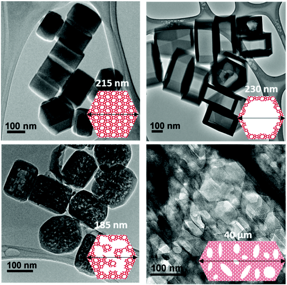 | ||
| Fig. 1 Transmission electron microscopy images and schematic representations of the different zeolite samples considered in this work: (top, left) small bulk silicalite-1 crystals, (top, right) corresponding small single hollow crystals, (bottom, left) small multihollow crystals and (bottom, right) large multihollow crystals. For each sample, a schematic of the porosity distribution is shown where one distinguishes the zeolite microporosity (red and white areas) and the added mesoporosity/macroporosity (white areas). Additional images are available in the ESI (Fig. S2 to S5).† | ||
2.2. Small bulk silicalite-1 synthesis
Silicalite-1 was prepared using tetraethylorthosilicate (TEOS, Aldrich, 98%) and homemade 1 M tetrapropylammonium hydroxide solution (TPAOH) obtained by reaction TPABr solution with Ag2O and water. The gel of composition SiO2![[thin space (1/6-em)]](https://www.rsc.org/images/entities/char_2009.gif) :0.4 TPAOH:35 H2O was stirred at room temperature overnight to fully hydrolyze the TEOS, then transferred into a Teflon-lined autoclave and heated at 170 °C under static conditions for 3 days. The autoclave was then cooled to room temperature and the solid was recovered by centrifugation, washed with water until pH = 7 and dried overnight at 90 °C. Finally, the resulting solid was calcined for 12 h at 525 °C in air, yielding bulk silicalite-1 crystals.
:0.4 TPAOH:35 H2O was stirred at room temperature overnight to fully hydrolyze the TEOS, then transferred into a Teflon-lined autoclave and heated at 170 °C under static conditions for 3 days. The autoclave was then cooled to room temperature and the solid was recovered by centrifugation, washed with water until pH = 7 and dried overnight at 90 °C. Finally, the resulting solid was calcined for 12 h at 525 °C in air, yielding bulk silicalite-1 crystals.
2.3. Small single hollow silicalite-1 synthesis
The hollow structure was obtained by a dissolution-recrystallisation process by treating the small bulk dry silicalite-1 in TPAOH solution at 170 °C.33,36 Typically, 1 g of dry zeolite was suspended in 7.5 mL of 0.55 M TPAOH solution, and then the mixture was heated at 170 °C under rotating conditions for 24 h. The solution was then cooled down, washed with water until pH 7, and dried overnight at 90 °C. Then the powder was calcined in air at 450 °C for 6 h yielding single hollow zeolite crystals.35,37,382.4. Small multi hollow silicalite-1 synthesis
The multi hollow structure was carried out by a post-synthesis desilication treatment in the presence of a phosphonium-containing structure-directing agent. Post-synthesis desilication was conducted by treating small bulk silicalite-1 with a commercial tetrabutylphosphonium hydroxide solution (TBPOH, Aldrich, 40 wt% in H2O). Typically, 1 g of dry zeolite was added to 4.5 mL of 1.125 M TBPOH solution. The mixture was then transferred into a Teflon-lined autoclave and heated at 115 °C under rotating conditions for 96 h. The solution was then cooled down, washed with water until pH 7, and dried overnight at 90 °C. Finally, the powder was calcined in air at 450 °C for 6 h yielding small multi hollow silicalite-1 zeolite crystals.352.5. Large multi hollow silicalite-1 synthesis
First, large bulk silicalite-1 crystals were synthesized thanks to one of our previous publications.34 Typically, tetraethylorthosilicate was hydrolyzed in a mixture of tetraethylammonium (TEAOH) and tetrabutylphosphonium (TBPOH) hydroxides (TEAOH/(TBPOH + TEAOH) = 0.25) and crystallized under static conditions at 170 °C for 4 days. The crystals obtained were recovered by centrifugation and named large bulk silicalite-1. Then, hollow structure was obtained by treating the large bulk dry silicalite-1 in TPAOH solution. Typically, 1 g of dry zeolite was suspended in 7.5 mL of 0.3 M TPAOH solution, and then the mixture was heated at 170 °C under rotating conditions for 72 h. The solution was then cooled down, washed with water until pH 7, and dried overnight at 90 °C. Then the powder was calcined in air at 540 °C for 6 h yielding large multi hollow silicalite-1 zeolite crystals.342.6. Characterization
For each sample considered in this study, X-ray diffraction (XRD) patterns were recorded on a Bruker D5005 diffractometer with Cu Kα radiation (λ = 1.5406 Å). Spectra were recorded over a 2θ range of 5°–80° with a step size of 0.02° and 1 s per step. A zoom in the region of 5°–55° 2θ was applied for better visualization. Transmission Electron Microscopy (TEM) images were obtained on a JEOL 2010 LaB6 microscope operating at 200 kV. A dispersion of the sample crushed in ethanol was deposited on standard holey carbon-covered copper TEM grids. Scanning electron microscopy (SEM) images were taken on a FEI ESEM-XL30 microscope.N2 adsorption/desorption isotherms were acquired at 77 K on a Belsorp-Mini (BEL-Japan) sorption apparatus. Circa 80 mg of sample was outgassed under vacuum in a cell at 300 °C overnight prior to adsorption. To ensure that equilibrium was reached during adsorption measurements, a stringent criterion known as floating criterion was used: equilibrium is assumed to be reached when the fluctuating pressure data do not vary more than 0.3% for at least a period of 500 s. Table 1 reports important properties that could be assessed using electron microscopy and routine characterization tools based on nitrogen experiments.
| Sample |
L × W × H (nm3)
|
S BET (m2 g−1) | V μ (cm3 g−1) | V C (cm3 g−1) | V tot (cm3 g−1) |
|---|---|---|---|---|---|
| a BET (Brunauer, Emmett et Teller) method. b Volume of N2 adsorbed when the slope of the adsorption branch becomes lower than 103 cm3 g−1. c Difference in N2 uptake between the adsorption and the desorption branches of the isotherms at P/P0 = 0.50. d Volume of N2 adsorbed at P/P0 = 0.90 from the desorption branch. | |||||
| Small bulk Si-1 | 215 × 175 × 130 | 440 | 0.15 | — | 0.22 |
| Large bulk Si-1 | 40 × 10 × 10 (μm3) | 345 | 0.14 | — | 0.17 |
| Small single hollow Si-1 | 230 × 190 × 145 | 370 | 0.12 | 0.12 | 0.33 |
| Small multihollow Si-1 | 185 × 150 × 115 | 445 | 0.14 | 0.24 | 0.57 |
| Large multihollow Si-1 | 40 × 10 × 10 (μm3) | 330 | 0.12 | 0.14 | 0.31 |
Electron tomography39 was performed employing the Environmental Transmission Electron Microscope (FEI-ETEM 80-300 keV) in vacuum. On the sample, well dispersed on a 200 mess Cu holy carbon grin, were added 5 nm Au nanoparticles used for image alignment. The tilt series were recording using the tomography plugin of the TIA software in High Angle Annular Dark Field Scanning Transmission Electron Microscopy (HAADF-STEM). The tilt series were tilted from −70° to +76° with an increment step de 2°. The tilt series were aligned using the Imod software,40 then the volume was reconstructed using SIRT-FISTA-TV algorithm developed in-house.41 The data segmentation, 3D model and quantification were performed using different plug-ins from Imagej and 3D Slicer.42
3. Results and discussion
3.1. Adsorption isotherms
Fig. 2 shows the N2 adsorption isotherms obtained at 77 K for the three hierarchical silicalite-1 samples: small single hollow silicalite, small multihollow silicalite, and large multihollow silicalite. For each sample, we also report the adsorption data obtained for the parent zeolite: small bulk silicalite crystals and large bulk silicalite crystal. The N2 adsorption isotherms for the three hierarchical samples display both features characteristic of adsorption in the zeolite and in larger mesoporous/macroporous cavities in agreement with previous works on hierarchical samples.43,44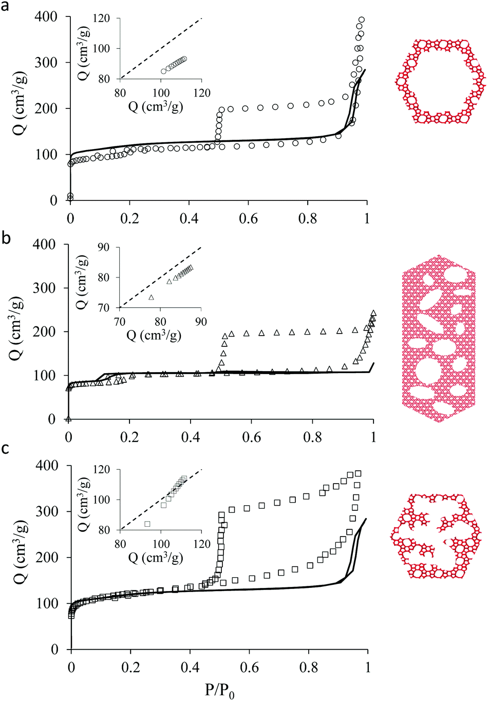 | ||
| Fig. 2 N2 adsorption isotherms at 77 K in hierarchical zeolites obtained from zeolite crystals: (a) small single hollow silicalite-1, (b) large multihollow silicalite-1, (c) small multihollow silicalite-1. For each sample, the symbols are for the hierarchical sample while the solid line corresponds to the N2 adsorption isotherm for the corresponding bulk zeolite crystals [small bulk silicalite-1 for (a) and (c) and large bulk silicalite-1 for (b)]. For each sample, the insert shows the adsorbed amount in the hierarchical sample at reduced pressures in the range [0.001–0.1] as a function of the adsorbed amount in the corresponding bulk zeolite at the same pressure. | ||
At low pressures, the adsorbed amount in these hierarchical porous solids increases very rapidly with pressures as filling of the zeolite microporosity occurs. Once the zeolite porosity is filled, the adsorbed amount for the hierarchical materials keeps increasing with pressure due to adsorption at the mesopore/macropore surface (i.e., multilayer adsorption regime). For all samples, at a pressure lower than the bulk saturating vapor pressure P0, the N2 adsorbed isotherms exhibits an irreversible increase that corresponds to capillary condensation/evaporation within the mesoporosity/macroporosity. Capillary hystereses observed for these samples will be analyzed in the next section but we can already discuss their overall shape. While the condensation branch spans over a non-negligible pressure range that is representative of the broad cavity size distribution in these samples, the evaporation branch is very steep as it corresponds to cavitation (indeed, considering that the cavities within the zeolite crystals are isolated from the external surface by zeolite domains, desorption can only occur through evaporation across this microporosity).
In contrast, adsorption in the zeolite regions does not display any hysteresis as pore filling becomes reversible and continuous in such very small pores (in fact, at a given temperature, there is a critical diameter below which pore filling and emptying no longer follows first order capillary condensation as observed for large pores27,45–47).
Before analyzing in detail the adsorption isotherms for the hierarchical samples, it is interesting to compare the corresponding data with those for the parent zeolite samples. We show in Fig. 2 an insert for each sample where the adsorbed amount in the hierarchical material is plotted as a function of the adsorbed amount obtained at the same reduced pressure in the parent solid. Such a comparison is relevant as the hierarchical samples are made of silicalite-1 zeolite so that they are supposed to have the same zeolite density, microporous specific volume and microporous specific surface area. As a result, differences in the adsorbed amount per unit of mass for a hierarchical material and its parent zeolite indicates non-negligible differences in their microporosity (see discussion in the next paragraph). On the other hand, this comparison is limited to the reduced pressure range [0.001–0.1] as adsorption at the external surface and filling in large, non-zeolitic cavities beyond these values makes the comparison between the hierarchical sample and its zeolite reference irrelevant. For all samples, the adsorbed amount in the hierarchical sample is found to be smaller than for the parent zeolite.
The smaller adsorbed amounts for the hierarchical samples with respect to their parent zeolite can be rationalized as follows. A lower degree of “crystallinity” cannot be invoked for the hierarchical samples according to XRD pattern and TEM images showing crystalline pattern in hollow crystals (see Fig. S2 and S3, respectively, of the ESI†). Instead, the lower microporous capacity for these hierarchical samples may originate from their low defect concentration. Indeed silicalite-1 crystals prepared in basic conditions are known to present a larger Si–OH defect concentration and, as a result, a larger apparent porous volume.48 Also, the adsorption step at 200–300 mbar in N2 adsorption at 77 K is absent – a feature that is characteristic of defective silicalite-1. Lastly, the associated Diffuse Reflectance Infrared Fourier Transform (DRIFT) spectra (Fig. S6†) confirm this observation with a hydroxyl region more intense for the bulk samples compared to the hierarchical ones. The series of bands at 3739, 3725 down to 3540 cm−1 are due to hydroxyl groups. The concentrations of free hydroxyl groups at 3739 cm−1 or intern silanol nests at 3540 cm−1 are markedly higher in the case of the bulk small crystals or bulk large crystals, respectively, compared to their hierarchical counterparts. It should be noted that the difference in quantity of external and internal silanols between samples can be due to crystals morphology diversity. For a better comparison, the bands at 2002 and 1880 cm−1 related to overtones were used as normalizing area for both small and large crystals. We can thus assume that the missing O–Si–O links for the parent zeolite leads to additional microporous volume with respect to more defect free crystals. In turn, such additional microporosity could explain the larger adsorbed amounts observed at low pressures for the parent zeolite compared to the hierarchical zeolite. Moreover, considering that the treatments used to form the different hollow zeolites involved either recrystallization or non-recrystallization processes, we note that differences in defect concentrations between the parent and hierarchical zeolites can also explain, to some extent, the variations observed in the adsorbed amounts.
The adsorption differences observed between the hierarchical and regular zeolites are consistent with the BET surface area reported in Table 1 for the conventional and hierarchical samples. For both the small and large samples, the BET surface area of the hierarchical samples is smaller or equal to its parent zeolite. In particular, we note that the difference between the adsorbed amount corresponding to the zeolite porosity in a hierarchical sample and its parent is directly related to the difference in their BET surface area. At this stage, we introduce a correction factor χ that is defined as the ratio of the adsorbed amount in the hierarchical sample and that in the zeolite parent. This factor is needed to correct each adsorption isotherm for its microporous contribution in order to proceed with the detailed analysis of the mesoporous contribution through extended adsorption-based characterization. Let us consider the mass of a hierarchical sample mh which adsorbs a quantity Nh(P) at a pressure P so that the specific adsorption isotherm is nh(P) = Nh(P)/mh. Similarly, for the parent zeolite, we can define nz(P) = Nz(P)/mz. As explained above, because of imperfect or incomplete crystallization, we have nh(P) < nz(P) provided P is taken in the low pressure range where adsorption at the external surface and in the large cavities is negligible. We can therefore define the correction factor as χ = nh/nz ≤ 1 (where χ = 1 is recovered if the zeolite domains in the regular and hierarchical sample are identical).
As mentioned above, χ should be independent of the pressure provided it is determined in the low pressure range where adsorption in non-zeolitic domains is negligible. However, for typical pressure ranges accessible in N2 adsorption experiments, χ can be found to depend on P. In practice, χ can be determined by plotting χ(P) as a function of P and by taking the limit when P tends to zero. Fig. 3 shows χ(P) for the three hierarchical samples. For the small single hollow sample, χSSH = 0.85 is defined unambiguously as it remains almost constant upon decreasing the pressure. In contrast, for the small multihollow sample, we see that χ increases with increasing the pressure (because of adsorption in the many large cavities) so that it can only be assumed that χSMH < 0.9. For the large crystal, χLMH = 0.94 is found to be nearly constant with pressure. While the comparison between χLMH and χSSH suggests that the large multihollow sample presents zeolite domains that are closer to those in its parent zeolite, these data should be interpreted with caution. Indeed, comparison between the adsorption isotherms for the two parent zeolites in Fig. 2 shows that the smaller zeolite crystals possess a larger microporosity since one obtains an adsorption isotherm with large adsorbed amounts in the microporous range (in contrast, the large zeolite crystals significantly underestimate the maximum adsorbed amount for this zeolite structure). As a result, if we determine χLMH using the reference adsorption data for the small bulk crystals, we obtain χLMH = 0.78 instead of 0.94 (see grey triangles in Fig. 3).
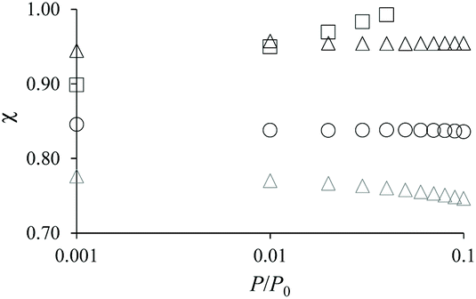 | ||
| Fig. 3 Correction factor χ as a function of N2 pressure for the small single hollow sample (black circles), the large multihollow sample (black triangles), and the small multihollow sample (black squares). χ = nh(P)/nz(P) is obtained by dividing the adsorbed amount nh(P) obtained at a pressure P for the hierarchical sample by the adsorbed amount nz(P) obtained at the same pressure for the parent zeolite. The grey triangles show χ when the adsorption data for the small bulk zeolite crystals are used as reference data instead of those for the large bulk zeolite crystals. | ||
3.2. Capillary condensation and cavity size distribution
Analyzing N2 capillary hystereses is a routine characterization technique to assess cavity size distributions. In this technique, the change in the adsorbed amount between pressures P and P + dP is written as the total volume Q(D) of the pores having a size D(P + dP) that fills at the pressure P + dP and a contribution arising from the change in the adsorbed amount in pores that are only partially filled [all cavity sizes > D(P + dP)]. Usually, the pressure P and cavity size D are related using a theory or model that describes capillary condensation/evaporation such as the Density Functional Theory (DFT),49 the Kelvin equation (BJH method),23 the Derjaguin model (BdB method),23etc. While these different models are more or less accurate, the assessment of cavity size distributions from N2 adsorption isotherms relies on simple assumptions that should be recalled when discussing the validity of the different methods. While these assumptions are robust for materials that present single, independent pores, they are usually poorly justified for real materials that display interconnected pores having a complex pore shape. First, pores are usually assumed to have a simple slit-like or cylindrical shape; this approximation leads to small yet non-negligible different cavity size distributions when analyzing a given material (because the relation that links the pore diameter D to the filling or emptying pressure P typically depends on the shape factor). Second, pore connectivity is known to drastically affect the way a pore fills or empties. For instance, it is usually assumed that a pore connected to the external phase through a neck will empty at the evaporation pressure corresponding to the neck (pore blocking) or at the gas nucleation pressure (cavitation). While such effects on pore emptying are often considered to characterize pore connectivity, it is often assumed that condensation (i.e. along the adsorption branch) is not affected by such pore boundary effects. Yet, in the spirit of pore-neck cooperative effects upon emptying, such boundary effects are also known to affect pore filling; for instance, a cylindrical pore connected to a small neck will not fill at the pressure Pc where the adsorbed cylindrical at its surface becomes unstable but at the pressure Pe corresponding to the Laplace pressure where the gas/liquid curved interface (formed at the junction between the neck and the pore) moves along the pore axis.50 In practice, this means that there is roughly a factor 2 between lnPc and lnPe (i.e. lnPe/Pc ∼ 2). This effect, known as advanced condensation or pore assisting factors, is equivalent to the pore blocking effect upon desorption but applied to adsorption.51
The paragraph above shows that assessing cavity size distributions relies on key assumptions which correspond to an ideal description of the porosity where some cooperative effects are neglected (e.g. advanced condensation). To our knowledge, while cooperative effects are often considered when analyzing capillary hystereses, such advanced condensation effects are not considered as accounting for both filling and emptying cooperative renders the problem intractable. In the spirit of conventional pore size analysis, our mathematical treatment below of the capillary hystereses observed for the zeolite hierarchical materials also rely on some of these assumptions. Regarding the pore shape, considering the morphology of the large cavities seen by electron microscopy in the bulk zeolite crystals, we use a spherical pore geometry rather than the usual slit or cylindrical geometry. We use Derjaguin's model which provides a robust and quantitative description of pore condensation and evaporation.52–55 Here, we simply recall the main ingredients of this seminal model (full derivation can be found elsewhere56,57). Considering a spherical pore of diameter D in contact with the fluid phase, the grand potential Ω of the adsorbed film of thickness t at the vapor pressure P and temperature T is given by: Ω = –PVv – PLVL + γSLASL + γLVALV + ALVWSLV(t) where P, PL, VV and VL are the pressure and volume of the vapor and adsorbed phases, respectively. γLV, γSL, ALV and ASL are the liquid/gas and liquid/solid surface tensions and surface areas, respectively. The interface potential WSLV(t) describes adsorption at the solid surface as it accounts for the interaction between the liquid/solid and adsorbate/gas interfaces. We choose WSLV(t) = Sexp[–t/ξ] as it provides an accurate description for nitrogen adsorption in cylindrical mesopores. For a given gas pressure P, the stable solution predicted using Derjaguin's model is obtained by determining the minimum in the grand potential Ω(t) upon varying t. After a little algebra, one shows that the capillary pressure for a spherical pore of diameter D is given by RT lnP(D)/P0 = –6γLV/[ρL(D − 2t)] × [1 + Sexp(–t/ξ)/γLV] (the detailed derivation can be found in ref. 56). Regarding pore boundary effects, as usually assumed when dealing with disordered porous materials, we consider that pore filling is not affected and, therefore, corresponds to the capillary condensation pressure for the spherical pore; this implies that cavity size distributions reported in this work should not be seen as true cavity size distributions but rather as the cavity size distribution of an assembly of equivalent pores having an ideal spherical geometry. On the other hand, while we neglect pore boundary effects upon condensation (advanced condensation), we consider in our analysis of the desorption branch possible pore blocking and cavitation effects (see below for more details).
Cavity size distributions can be assessed from nitrogen adsorption data by solving the following integral equation which states that the total adsorbed amount Q(P) at a pressure P is the sum of the adsorption isotherm n(P, D) in a pore of diameter D weighed by the total porous volume f(D) corresponding to this pore category:
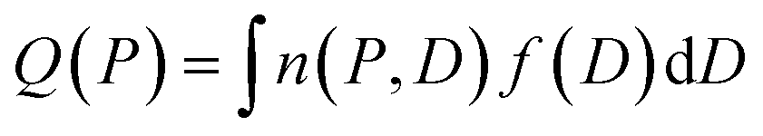 | (1) |
This is a well-known problem in adsorption science where one has to consider that, upon changing the pressure from P to P + dP, the change in the adsorption isotherm corresponds to pore filling as well as variation in the adsorbed amount due to pores that are not filled at the pressure P + dP. To solve eqn (1) for the small hollow silicalite-1, small multihollow silicalite-1, and large multihollow silicalite-1, we wrote a numerical code based on a Monte Carlo approach. First, using the analysis reported in Section 3.1, we correct each adsorption isotherm for the zeolite contribution; based on previous work,43 we write that the total adsorption isotherm is the sum of the adsorbed amount in the zeolitic part and the adsorbed amount in the mesoporosity/macroporosity. In practice, this is achieved by fitting the overall adsorption isotherm at each pressure against the adsorbed amount for the zeolite sample with the same crystalline size so that the residual adsorption isotherm is assumed to correspond to the number of molecules in the mesoporosity (this is equivalent to correcting the adsorption isotherms for the correction factor χ discussed above). After correcting the experimental adsorption isotherms for the zeolite contribution, we start from an initial mesoporous cavity distribution which possesses the correct pore volume (obtained by summing the volume corresponding to each cavity size multiplied by their occurrence/weight in the cavity size distribution). This starting cavity size distribution is used as an initial guest whose details do not matter as it is evolving along the Monte Carlo strategy to converge towards the final distribution. To reach a cavity size distribution that allows matching the experimental adsorption isotherm, we update the cavity size distribution by attempting to transfer a small pore volume amount ΔV corresponding to a given cavity size D to another cavity size D′. Such a pore volume displacement, which can be written as V(D′) → V(D′) + ΔV and V(D) → V(D) − ΔV, induces a change in the adsorbed amount from Q(P) → Q(P) + ΔQ(P). We note that this Monte Carlo perturbation ensures that the porous volume – which is initially set to reproduce the experimental porous volume – remains constant. In this Monte Carlo approach, the attempted volume transfer from one cavity size to another is accepted or rejected using the following acceptance probability:
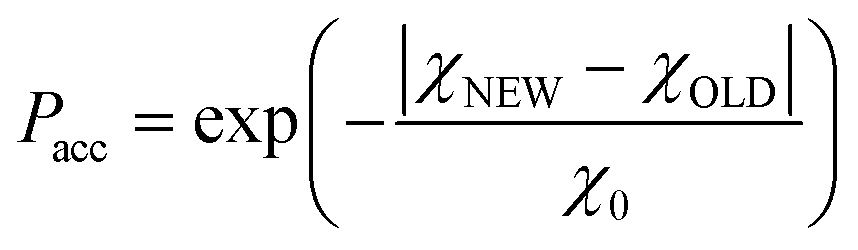 | (2) |
In this equation, χNEW and χOLD are the χ-square difference between the experimental and simulated adsorption isotherm after and before the pore volume change:
 | (3) |
In the next paragraphs, we analyze the data obtained for the three hierarchical samples: small single hollow, small multihollow, and large multihollow zeolites. Among these three samples, we first discuss the small single hollow zeolite as it can be seen as an ideal sample which allows illustrating in a simple and efficient way the concepts and methods proposed in this work. Indeed, this sample possesses a single large cavity in each crystal (particle) so that we rather probe the homogeneity in crystal sizes.
Fig. 4(a) compares the simulated adsorption isotherm against the experimental data for the small hollow zeolite. Fig. 4(b) shows the corresponding cavity size distribution inferred from our Monte Carlo approach for the same sample (red histogram). As can be seen from these data, our numerical strategy allows reproducing very accurately the experimental adsorption isotherm. As expected for this sample (which corresponds to ∼100 nm hollow particles), the cavity size is broad with a characteristic cavity size that is around 80–100 nm. To verify the quality of the inferred cavity size distribution, we report in Fig. 5 the data obtained by electron tomography for the same sample. While such tomography was obtained for a limited number of particles, the estimated pore length, width and height provide an estimate for the typical cavity size distribution in this small hollow silicalite-1 sample. As shown in Fig. 5(b), the cavity size distribution seen by tomography, which is broad with a maximum around 80–100 nm, is fully consistent with the data obtained using our cavity size distribution analysis.
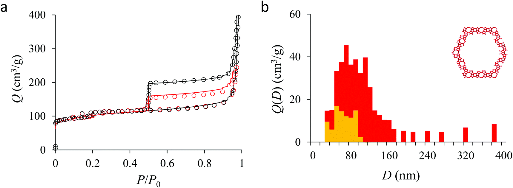 | ||
| Fig. 4 (a) N2 adsorption isotherms at 77 K in the small single hollow silicalite-1. The black circles correspond to the main adsorption/desorption isotherm (pressures up to P ∼ 0.999P0). The red circles correspond to a descending scanning curve starting from P ∼ 0.97P0. The solid and red lines correspond to the analytical model based on Derjaguin's theory for spherical pores (see text). (b) cavity size distribution for the small hollow silicalite-1 sample as determined from the analytical model based on Derjaguin's theory. The red data show the entire cavity size distribution while the orange data show the subdistribution corresponding to the closed pores (no direct access to the external surface). | ||
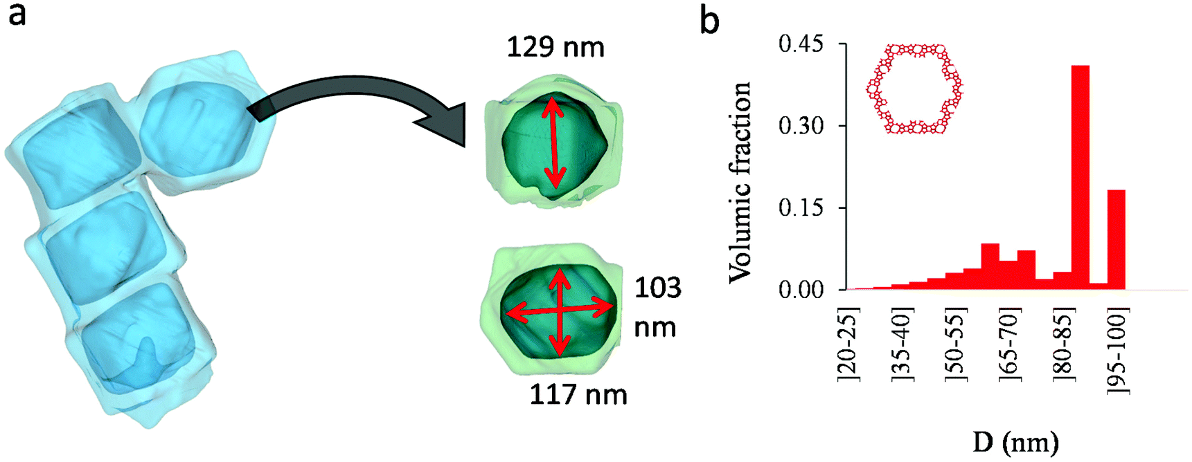 | ||
| Fig. 5 (a) Tomography view of the small single hollow silicalite-1. Four cavities were considered to estimate the length, width, and height of the macroporous cavity inside the zeolite crystals. (b) cavity size distribution as seen from electron tomography. | ||
We now analyze the adsorption isotherms obtained for the multihollow samples with either large or small particles. The simulated and experimental adsorption isotherms for the large and small multihollow samples are shown in Fig. 6 and 7, respectively. Like for the hollow silicalite-1 sample above, the simulated adsorption isotherms perfectly reproduce the experimental data. As for the corresponding cavity size distributions (red histograms), as expected for such samples displaying significant dispersion in cavity size, the cavity size distributions are very broad with cavity sizes up to a few 100 nm. Due to the large particle size in the large multihollow sample, the cavity size distribution extends to much larger cavity sizes. In particular, due to the elongated shape of the particles in the large multihollow sample, the cavity size distribution is bimodal. On the other hand, the first cavity size distribution centered around 80–100 nm is similar to that observed for the small multihollow sample. As a result, these pores are assumed to correspond to porosity aligned along the small dimension of the elongated particles. On the other hand, there is a second cavity size distribution >120 nm that is assumed to correspond to pores that are aligned with the large dimension of the particles.
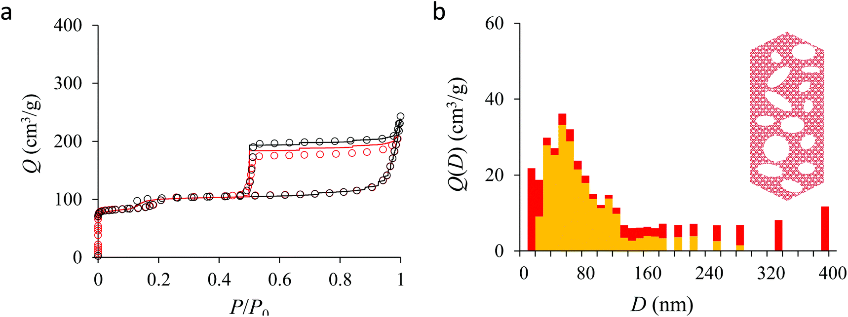 | ||
| Fig. 6 (a) N2 adsorption isotherms at 77 K in the large multihollow silicalite-1. The black circles correspond to the main adsorption/desorption isotherm (pressures up to P ∼ 0.999P0). The red circles correspond to a descending scanning curve starting from P ∼ 0.99P0. The solid and red lines correspond to the analytical model based on Derjaguin's theory for spherical pores (see text). (b) cavity size distribution for the small hollow silicalite-1 sample as determined from the analytical model based on Derjaguin's theory. The red data show the entire cavity size distribution while the orange data show the subdistribution corresponding to the closed pores (no direct access to the external surface). | ||
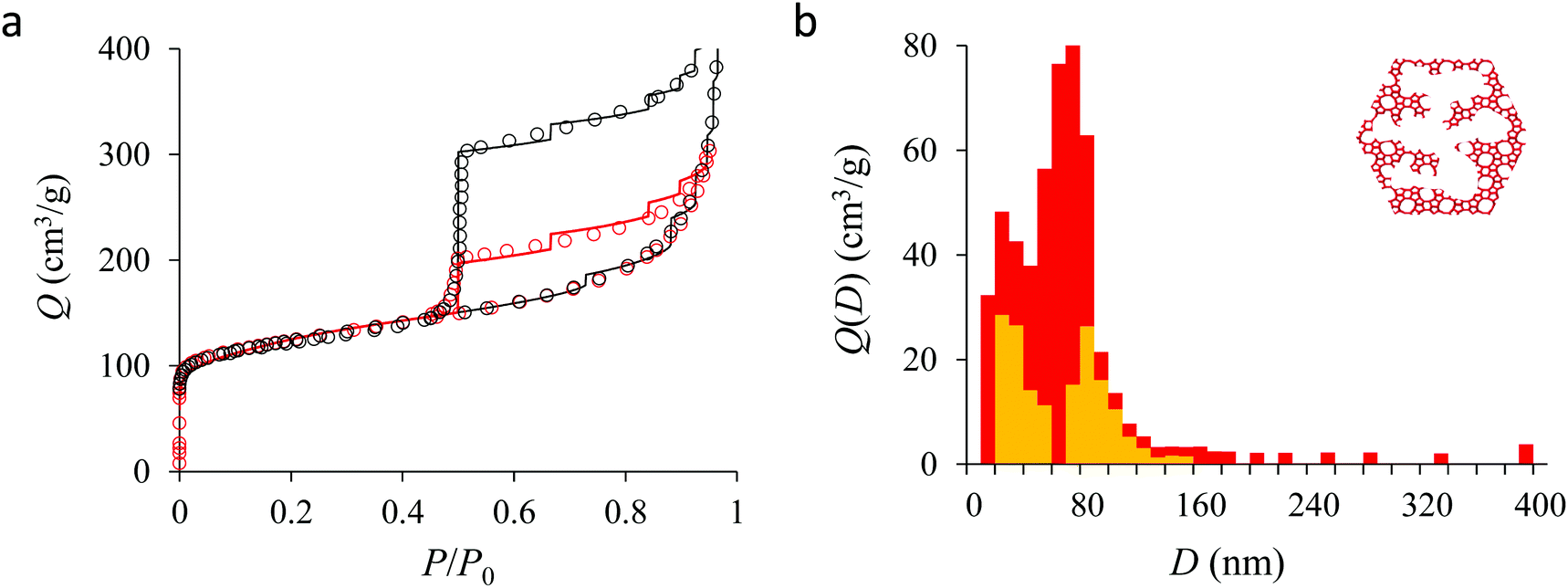 | ||
| Fig. 7 (a) N2 adsorption isotherms at 77 K in the small multihollow silicalite-1. The black circles correspond to the main adsorption/desorption isotherm (pressures up to P ∼ 0.999P0). The red circles correspond to a descending scanning curve starting from P ∼ 0.95P0. The solid and red lines correspond to the analytical model based on Derjaguin's theory for spherical pores (see text). (b) cavity size distribution for the small multihollow silicalite-1 sample as determined from the analytical model based on Derjaguin's theory. The red data show the entire cavity size distribution while the orange data show the subdistribution corresponding to the closed pores (no direct access to the external surface). | ||
3.3. Capillary hystereses and pore boundaries
We now analyze the capillary hystereses observed for the hollow zeolites. Such data provide complementary information with respect to the adsorption branch as they allow inferring pore boundaries. In more detail, while it is usually assumed that the cavity size distribution inferred from the adsorption branch is not affected by pore ending/connectivity, the desorption is known to reflect pore boundaries. In this context, the shape of the adsorption hysteresis is known to be characteristic of the morphology (pore shape) and topology (pore connectivity) of the pore network.21,30 On the one hand, independent pores with a regular shape lead to capillary hystereses with symmetrical adsorption/desorption branches (H1 hysteresis); in this case, both the adsorption and desorption branches reflect the width of the cavity size distribution. On the other hand, connected pores with either a regular or irregular shape lead to capillary hystereses with a desorption branch that is much steeper than the adsorption branch (H2 hysteresis); in this case, the adsorption branch reflects the cavity size distribution while the desorption branch reflects the neck size distribution (which is narrower than the main cavity size distribution by definition). Such a well-established formalism offers the ground for advanced morphological/topological characterization of the pore network in materials science. Yet, while such tools are already available, the underlying data analysis is more complicated as desorption in irregular and/or connected pores depend on the neck size that isolates the pore from its neighbors. In more detail, depending on the pore and neck sizes, desorption can occur either through pore blocking or cavitation. On the one hand, when the neck size d is larger than a critical diameter Dc, desorption occurs through pore blocking at a desorption pressure corresponding to the emptying pressure corresponding to the neck diameter d (i.e. the pore of size D empties automatically as the neck that isolates it from outside empties). On the other hand, when the neck size d is smaller than Dc, the pore of size D empties at the cavitation pressure of the adsorbate fluid at the temperature T (i.e., the pressure becomes too small to be sustained by the confined fluid so that it evaporates even if the neck remains filled by the liquid). In particular, for the zeolite samples considered here (with mesoporosity/macroporosity encapsulated in the zeolite), starting from samples completely filled with the liquid phase, all pores are isolated from the external environment through the zeolite porosity. As a result, with such configurations, in agreement with the adsorption isotherms reported in Fig. 5–7, we expect most porosity to empty through cavitation.In order to use the framework above to analyze desorption phenomena in hollow zeolites, we adopted the following numerical approach which is applied to the desorption branch. Like for the previous section (adsorption branch analysis), our strategy relies on a numerical treatment of the data which involves the following assumptions. First, as can be seen from the sharp drop along the desorption branch in the experimental data for the hollow zeolites (Fig. 5–7), the cavitation pressure for N2 at 77 K is estimated as Pcav ∼ 0.45–0.50P0. Using Derjaguin's model, this cavitation pressure corresponds to a critical neck size Dc ∼ 2 nm. Second, we assume that the cavity size distribution V(D) for each hollow zeolite sample corresponds to that inferred from the adsorption branch in Section 3.2. With these assumptions, we can determine from the desorption branch the fraction of cavity size D that (1) is directly in contact with the external environment or (2) encapsulated in the zeolite porosity and hence not in direct contact with the external phase (in what follows, the former and latter pores are coined as open and closed pores, respectively). Indeed, while pores isolated from the external phase will empty through cavitation at Pcav (since the zeolite cavity size is smaller than Dc), the open pores in contact with the external phase will empty at a pressure corresponding to their pore diameter as given by Derjaguin's equation applied to the desorption branch. In simple words, all pore volume corresponding to a desorption pressure P > Pcav is attributed to the porosity associated with the cavity size D while all pore volume that empties at P ∼ Pcav is attributed to cavities encapsulated in the zeolite porosity (in the latter case, the pore volume cannot be attributed to given cavity sizes at the desorption pressure is only reflecting the fact that the neck size is such that d < Dc).
Fig. 5, 6, and 7 compare the simulated desorption branch against the experimental data for the small single hollow, large multihollow zeolite, and small multihollow zeolites, respectively. As already mentioned, for all samples, the very steep desorption branch at P ∼ Pcav indicates that most of the mesoporosity/macroporosity empties through cavitation. However, while this result was expected for such zeolite samples in which most large pores are encapsulated within the zeolite, some non-negligible meso/macroporosity is found to be connected directly to the external environment. Such open large porosity is directly observable from the desorbed volume between full loading (P ∼ P0) and the loading prior to cavitation (P ∼ Pcav). Reciprocally, the amount of mesoporosity encapsulated in the zeolite particles correspond to the volume desorbed prior (P = Pcav + ε) and after (P = Pcav − ε) cavitation (with ε ∼ 0). As can be seen in Fig. 5–7, the simulated data reproduce accurately the experimental data which confirms the ability of our data analysis to infer relevant cavity size distributions corresponding to the open porosity. For each sample, such a cavity size distribution restricted to meso/macropores directly in contact with the external environment are shown in panel b of Fig. 5–7. As expected for the single hollow zeolite, most meso/macroporosity is encapsulated in the zeolite particles with only a small amount of porosity directly in contact with the external phase through the particle external surface area (extra-particle porosity). In contract, for the small and large multihollow samples, which possess a much more disordered meso/macroporosity with pores of a distorted shape and significantly connected, the fraction of meso/macroporosity is more important. As observed for the meso/macroporosity distribution probed using the adsorption branch, the cavity size distribution corresponding to the opened porosity is broader for the large multihollow sample than for the small multihollow sample. This result simply reflects that, owing to its larger particle size, the large multihollow sample necessarily possesses pores that span a larger cavity size range compared to the small multihollow sample (for each sample, the particle size imposes an upper boundary for the cavity size distribution). This information is supported by TEM microscopy images, see as illustration the Fig. S2 and S3.† In this context, we underline that the discussion on pore size distributions between samples with very different crystalline particle sizes is not straightforward since they necessary cover different ranges.
3.4. Scanning behavior and pore connectivity
In his seminal work, Everett introduces a simple model – known as the independent domain theory – which provides a mean to analyze the pore connectivity and hence the pore network disorder from scanning curves measurements.27,31 Such adsorption measurements consist of probing the desorption from a sample that is initially only partially filled (descending scanning curve) or probing the adsorption from a sample that is initially only partially emptied (ascending scanning curve). To further characterize the porosity in the hierarchical zeolites under study, we measured descending scanning curves which are shown as red circles in Fig. 5–7. Such experimental data can be interpreted as follows. Using the independent domain theory, at the starting point of the descending scanning curves P = Pdes, we assume that all cavity sizes D such that the condensation pressure P(D) ≤ Pdes are filled (in contrast, cavity sizes such that P(D) > Pdes are only partially filled with an adsorbed film at the pore surface). Upon decreasing the pressure from P to P − dP, the pores that are open to the external phase can empty through pore evaporation while those that are not completely filled desorb molecules due to the decrease in the adsorbed film thickness. In contrast, the mesopores which are encapsulated in the zeolite particles and initially filled by the liquid at Pdes are assumed to remain filled until they reach the cavitation pressure. As clearly seen from these assumptions, in this model, the pores are assumed to behave independently (hence, the name “independent domain theory”). In contrast, in real samples showing sufficient pore connectivity, the fact that neighboring pores are empty or filled with the liquid will affect the desorption of the pores initially filled. Therefore, by comparing the predictions of the independent domain theory with the experimental scanning curves, one can infer whether or not the meso/macropores behave independently from each other. Despite its complexity, the independent domain theory is a method of choice which can be used to characterize the connectivity in disordered porous samples such as porous silicon, hierarchical porous zeolites, etc.26,28,29,58Fig. 5, 6 and 7 compare the experimental descending scanning curves with those predicted using the independent domain theory for the single hollow, small multihollow and large multihollow zeolites, respectively. The predicted scanning curves are close to their experimental counterpart, therefore suggesting that the three zeolite samples possess meso/macropores that behave mostly independently from each other. As expected, due to the fact that some of the large porosity consists of pores connected to each other, the predicted descending scanning curve overestimates the experimental adsorbed amount at each pressure (even if the differences remain overall small). Again, this result is due to the fact that the independent domain theory assumes that all pores behave independently and, hence, neglects that the desorption of some pores is facilitated as their neighbors are already empty. The comparison between the data for the two multihollow zeolites suggests that the pores are more connected in the large multihollow sample than in the small multihollow sample (since the difference between the theoretical and experimental scanning curves is larger for the former than for the latter). This result is in contrast with the known morphology for the small multihollow zeolite which suggests that the mesoporosity is more disordered and, hence, presumably more connected than for the single hollow and large multihollow. While these results seem contradictory, they can be rationalized by noting that the pressure Pdes at which the descending scanning curve is performed is lower for the small multihollow zeolite (Pdes ∼ 0.95P0) than for the single hollow and large multihollow zeolites (Pdes ∼ 0.97P0 and Pdes ∼ 0.99P0, respectively). As a result, the fraction of porosity already emptied is larger for the small hollow sample than for the two other samples so that the difference between dependent and independent pores leads to lower adsorbed volume variations.
As shown in the previous analyses, adsorption/desorption data in such multiscale porous materials provide key information that are otherwise difficult to infer from other techniques. In particular, by analyzing the desorption from both completely filled (main desorption) and partially filled samples (descending scanning), one can obtain important data regarding the pore network connectivity. On the other hand, one drawback of such approaches lies in the presence of cavitation which prevents from deriving a neck size distribution; indeed, because cavitation is an intrinsic property of the probe fluid at a given temperature (here, nitrogen at 77 K), one can only infer the maximum neck size distribution. In other words, when cavitation is observed, one can only assert that the neck isolating the fluid in the main cavity from its external environment is such that its diameter is smaller than Dc. Considering that Dc is of the order of a few nm, this makes is difficult to fully characterize the porosity in multiscale porous solids such as hierarchical zeolites. In this case, in complement of all adsorption-based characterization techniques, tomography such as electron tomography is a method of choice as it provides additional information (we note that it is also often recommended to get data from different adsorbates to obtain complementary information22). To illustrate the ability of such techniques to probe neck/cavity sizes, we show in Fig. 8(a) a tomography view of a representative crystal corresponding to the small multihollow silicalite-1 sample. These data were used to assess in Fig. 8(b) the cavity size distribution (pores) but also the neck size distribution (junctions). Such analysis reveals that the junction size distribution is centered around D ∼ 2.0–3.5 nm. Such characteristic neck size, which is of the order of Dc, is fully consistent with our analysis based on nitrogen desorption data and associated scanning behavior. Indeed, such narrow constrictions with D < Dc must be invoked to rationalize the steep desorption branch observed at P ∼ Pcav in the main desorption data and desorption scanning data.
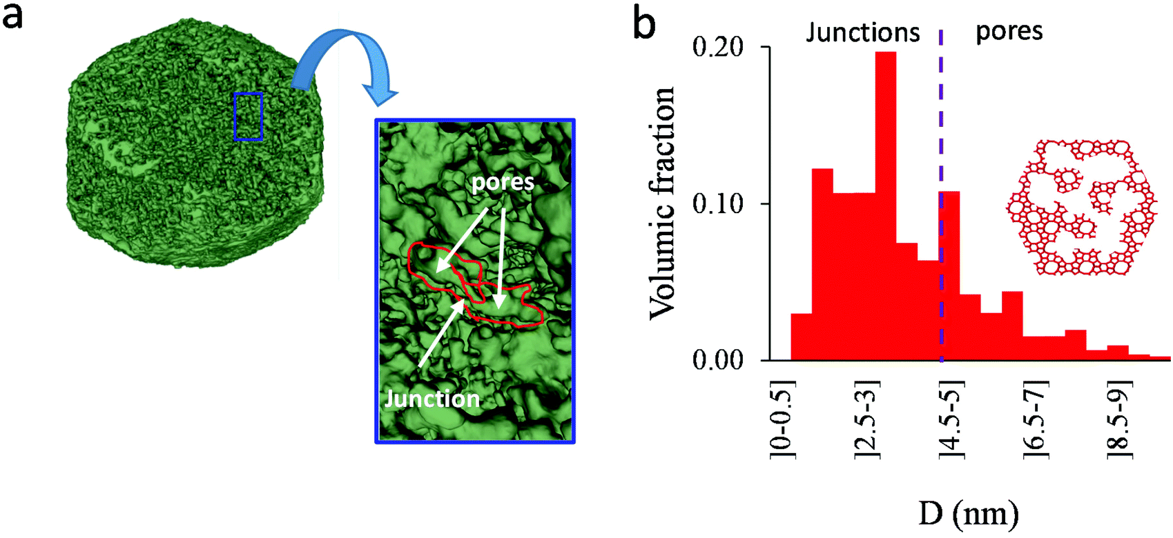 | ||
| Fig. 8 (a) Tomography view of a representative crystal corresponding to the small multihollow silicalite-1 sample. The size of the sample is about 185 × 150 × 115 nm3. The porosity is shown in green. (b) Cavity size distribution as seen from electron tomography. | ||
4. Conclusions
Nitrogen adsorption at low temperature was used to perform extended characterization of the morphological and topological properties of the pore network in hollow zeolite particles. Our analysis is based on three complementary adsorption-based techniques: pore size distribution, distribution of closed/open pores, and pore connectivity. None of these aspects is novel but the combination of these three aspects is not standard. Moreover, while hysteresis scanning is a method of choice that has been used in the past to characterize porous media (see above references), the hierarchical zeolite samples considered in our study – without being ideal – constitute an important playground to test the combined used of these analyses (even if additional techniques such as microscopy and tomography data are needed to guide and/or corroborate the inferred information).While such hollow zeolites (in particular the single hollow zeolite crystals) may not be representative of the hierarchical porosities found in practical zeolites, their homogeneity in terms of crystal and cavity dimensions make them ideal materials to understand low temperature N2 adsorption/desorption measurements with the aim to establish qualitative and quantitative pore structure analysis. The power of such advanced characterization techniques – which include analyzing adsorption and desorption branches but also scanning of the desorption within the capillary hysteresis loop – was illustrated here by considering different hollow zeolite types: (1) hollow zeolite particles, (2) zeolite particles with connected multihollow porosity, and (3) elongated zeolite particles with rather independent multihollow porosity. In more detail, regardless of the porosity distribution within the particles, by using a numerical approach to solve the integral equation linking the adsorbed amount at a given pressure to the cavity size distribution, we illustrate that the main adsorption branch for such complex architectured samples can be used to derive quantitative cavity size distributions that reflect the whole porosity. Moreover, by considering the desorption branch, the amount of closed porosity for each cavity size in the main cavity size distribution can be inferred. Finally, additional important information regarding the connectivity of the meso/macropore distribution within the zeolite particles can also be derived by scanning the desorption of the system that is only partially filled at the start of the emptying process. Such data, which were compared with electron tomography, were found to provide complementary information about the way the porosity is distributed in such complex zeolitic materials.
With the recent boost in the synthesis and design of architectured nanoporous materials, more and more advanced zeolite materials (e.g. hierarchical zeolites, zeolite films, nanozeolites, dendritic zeolites, etc.5,6,59–62) are available in the literature. Such rapid developments challenge currently available characterization techniques which must be complemented by adding extended methods such as combined approaches for instance. In this respect, on top of classical techniques such as X-ray, electron tomography and microscopy, adsorption remains the method of choice to probe the porosity and surface area in zeolite solids but also in other nanoporous solids (Metal Organic Framework, carbon, etc.). As illustrated in the present paper, adsorption-based strategies beyond BET surface and cavity size assessment provide key information regarding the pore network topology/morphology. In particular, we emphasize that these methods are complementary of the data obtained from tomography and microscopy techniques as they probe the sample entirely (no sensitivity to the Representative Elementary Volume being probed). On the other hand, we found that in most cases adsorption-based characterization should be guided by constraining the analysis using additional data from other techniques such as those cited above. A new momentum in the field of porous media characterization is needed as an increasing number of applications in separation but also in catalysis are based on the synthesis and development of architectured nanoporous solids with specific pore network topology and morphology. Such design efforts must be accompanied/guided using robust adsorption-based characterization techniques. In this context, we note that well-known additional techniques are available to successfully characterize multiscale porous materials such as hierarchical solids. Among such methods, one can find Hg porosimetry and other gases such as Ar at 87 K and CO2 at room temperature for adsorption-based characterization. In the context of the present study, we note that mercury porosimetry is not suitable as the meso/macro porosity to be analyzed is only accessible through the zeolite microporosity (as a result, very large intrusion pressures would have to be considered with unavoidable damage for the samples). On the other hand, complementary adsorption using Ar or CO2 as probe molecules would provide additional insights. While CO2 adsorption would allow fine characterization of the zeolite porosity, Ar adsorption in combination with N2 adsorption is known to provide important data regarding the complex porosity in multiporosity samples.
Conflicts of interest
There are no conflicts to declare.Acknowledgements
This work was supported by the French Research Agency (ANR CATCALL (ANR-19-CE07-0025)). Numerical calculations in this paper were performed using the Froggy platform of the GRICAD infrastructure (https://www.gricad.univ-grenoble-alpes.fr), which is supported by the Rhône-Alpes region (GRANT CPER07-13 CIRA) and the Equip@Meso project (reference ANR-10-EQPX-29-01) of the program Investissements d'Avenir supervised by the French Research Agency. LR thanks CLYM for granting the access to the ETEM microscope.References
- K. Tanabe, Industrial application of solid acid–base catalysts, Appl. Catal., A, 1999, 181, 399–434 CrossRef CAS.
- M. E. Davis, Zeolites and molecular sieves: not just ordinary catalysts, Ind. Eng. Chem. Res., 1991, 30, 1675–1683 CrossRef CAS.
- V. van Speybroeck, K. Hemelsoet, L. Joos, M. Waroquier, R. G. Bell and C. R. A. Catlow, Advances in theory and their application within the field of zeolite chemistry, Chem. Soc. Rev., 2015, 44, 7044–7111 RSC.
- A. Corma, Inorganic Solid Acids and Their Use in Acid-Catalyzed Hydrocarbon Reactions, Chem. Rev., 1995, 95, 559–614 CrossRef CAS.
- V. Valtchev and S. Mintova, Hierarchical zeolites, MRS Bull., 2016, 41, 689–693 CrossRef CAS.
- J. Pérez-Rami-rez, D. Verboekend, A. Bonilla and S. Abello, Zeolite Catalysts with Tunable Hierarchy Factor by Pore-Growth Moderators, Adv. Funct. Mater., 2009, 19, 3972–3979 CrossRef.
- S. Polarz and B. Smarsly, Nanoporous materials, J. Nanosci. Nanotechnol., 2002, 2, 581–612 CrossRef CAS PubMed.
- L. R. Aramburo, L. Karwacki, P. Cubillas, S. Asahina, D. A. M. de Winter, M. R. Drury, I. L. C. Buurmans, E. Stavitski, D. Mores, M. Daturi, P. Bazin, P. Dumas, F. Thibault-Starzyk, J. A. Post, M. W. Anderson, O. Terasaki and B. M. Weckhuysen, The porosity, acidity, and reactivity of dealuminated zeolite ZSM-5 at the single particle level: the influence of the zeolite architecture, Chemistry, 2011, 17, 13773–13781 CrossRef CAS PubMed.
- D. N. Rainer and M. Mazur, in Catalysis, ed. J. Spivey, Y.-F. Han and D. Shekhawat, Royal Society of Chemistry, Cambridge, 2020, pp. 151–187 Search PubMed.
- R. L. Volkov, V. N. Kukin, P. A. Kots, I. I. Ivanova and N. I. Borgardt, Complex Pore Structure of Mesoporous Zeolites: Unambiguous TEM Imaging Using Platinum Tracking, ChemPhysChem, 2020, 21, 275–279 CrossRef CAS PubMed.
- Y. Bouizi, G. Majano, S. Mintova and V. Valtchev, Beads Comprising a Hierarchical Porous Core and a Microporous Shell, J. Phys. Chem. C, 2007, 111, 4535–4542 CrossRef CAS.
- L. Roiban, S. Li, M. Aouine, A. Tuel, D. Farrusseng and T. Epicier, Fast ‘Operando’ electron nanotomography, J. Microsc., 2018, 269, 117–126 CrossRef CAS PubMed.
- M. Lions, C. Daniel, B. Coasne, F. Meunier, A. Tuel and D. Farrusseng, The Pivotal Role of Critical Hydroxyl Concentration in Si-Rich Zeolites for Switching Vapor Adsorption, J. Phys. Chem. C, 2021, 125, 22890–22897 CrossRef CAS.
- S. Amani, A. B. Garmarudi, M. Khanmohammadi and F. Yaripour, Application of diffuse reflectance near-infrared spectrometry and chemometrics in characterization of micro and mesoporous ZSM-5 zeolites, RSC Adv., 2018, 8, 34830–34837 RSC.
- B. Smarsly, C. Göltner, M. Antonietti, W. Ruland and E. Hoinkis, SANS Investigation of Nitrogen Sorption in Porous Silica, J. Phys. Chem. B, 2001, 105, 831–840 CrossRef CAS.
- L. A. Solovyov, O. V. Belousov, R. E. Dinnebier, A. N. Shmakov and S. D. Kirik, X-ray diffraction structure analysis of MCM-48 mesoporous silica, J. Phys. Chem. B, 2005, 109, 3233–3237 CrossRef CAS PubMed.
- G. A. Zickler, S. Jähnert, W. Wagermaier, S. S. Funari, G. H. Findenegg and O. Paris, Physisorbed films in periodic mesoporous silica studied by in situ synchrotron small-angle diffraction, Phys. Rev. B: Condens. Matter Mater. Phys., 2006, 73, 184109 CrossRef.
- S. Jähnert, D. Müter, J. Prass, G. A. Zickler, O. Paris and G. H. Findenegg, Pore Structure and Fluid Sorption in Ordered Mesoporous Silica. I. Experimental Study by in situ Small-Angle X-ray Scattering, J. Phys. Chem. C, 2009, 113, 15201–15210 CrossRef.
- N. Muroyama, A. Yoshimura, Y. Kubota, K. Miyasaka, T. Ohsuna, R. Ryoo, P. I. Ravikovitch, A. V. Neimark, M. Takata and O. Terasaki, Argon Adsorption on MCM-41 Mesoporous Crystal Studied by In Situ Synchrotron Powder X-ray Diffraction, J. Phys. Chem. C, 2008, 112, 10803–10813 CrossRef CAS.
- F. Benaliouche, N. Hidous, M. Guerza, Y. Zouad and Y. Boucheffa, Characterization and water adsorption properties of Ag- and Zn-exchanged A zeolites, Microporous Mesoporous Mater., 2015, 209, 184–188 CrossRef CAS.
- M. Thommes, Physical Adsorption Characterization of Nanoporous Materials, Chem. Ing. Tech., 2010, 82, 1059–1073 CrossRef CAS.
- K. A. Cychosz, R. Guillet-Nicolas, J. García-Martínez and M. Thommes, Recent advances in the textural characterization of hierarchically structured nanoporous materials, Chem. Soc. Rev., 2017, 46, 389–414 RSC.
- F. Rouquerol, J. Rouquerol, K. S. Sing, P. Llewellyn and G. Maurin, Adsorption by powders and porous solids. Principles, methodology and applications, Academic press, Amsterdam, Paris etc., 2014 Search PubMed.
- A. I. Sagidullin and I. Furó, Pore size distribution measurements in small samples and with nanoliter volume resolution by NMR cryoporometry, Langmuir, 2008, 24, 4470–4472 CrossRef CAS PubMed.
- J. Mitchell, J. Webber and J. Strange, Nuclear magnetic resonance cryoporometry, Phys. Rep., 2008, 461, 1–36 CrossRef CAS.
- R. Cimino, K. A. Cychosz, M. Thommes and A. V. Neimark, Experimental and theoretical studies of scanning adsorption–desorption isotherms, Colloids Surf., A, 2013, 437, 76–89 CrossRef CAS.
- B. Coasne, K. E. Gubbins and R. J.-M. Pellenq, Domain theory for capillary condensation hysteresis, Phys. Rev. B: Condens. Matter Mater. Phys., 2005, 72, 024304 CrossRef.
- D. Schneider, D. Kondrashova and R. Valiullin, Phase transitions in disordered mesoporous solids, Sci. Rep., 2017, 7, 7216 CrossRef PubMed.
- S. Mitchell, A. B. Pinar, J. Kenvin, P. Crivelli, J. Kärger and J. Pérez-Ramírez, Structural analysis of hierarchically organized zeolites, Nat. Commun., 2015, 6, 8633 CrossRef CAS PubMed.
- P. A. Monson, Understanding adsorption/desorption hysteresis for fluids in mesoporous materials using simple molecular models and classical density functional theory, Microporous Mesoporous Mater., 2012, 160, 47–66 CrossRef CAS.
- D. H. Everett, The Solid-Gas Interface, Marcel Dekker, New York, 1967 Search PubMed.
- L. Burel and A. Tuel, Nanozeolites: New strategies for designing ultra small silicalite crystals with very few framework defects, Microporous Mesoporous Mater., 2013, 174, 90–99 CrossRef CAS.
- S. Li, T. Boucheron, A. Tuel, D. Farrusseng and F. Meunier, Size-selective hydrogenation at the subnanometer scale over platinum nanoparticles encapsulated in silicalite-1 single crystal hollow shells, Chem. Commun., 2014, 50, 1824–1826 RSC.
- N. Novruzova, A. Tuel, D. Farrusseng and F. C. Meunier, Influence of crystal size on the uptake rate of isooctane in plain and hollow silicalite-1 crystals, Microporous Mesoporous Mater., 2016, 228, 147–152 CrossRef CAS.
- D. Laprune, A. Tuel, D. Farrusseng and F. C. Meunier, Highly Dispersed Nickel Particles Encapsulated in Multi-hollow Silicalite-1 Single Crystal Nanoboxes: Effects of Siliceous Deposits and Phosphorous Species on the Catalytic Performances, ChemCatChem, 2017, 9, 2297–2307 CrossRef CAS.
- S. Li, L. Burel, C. Aquino, A. Tuel, F. Morfin, J.-L. Rousset and D. Farrusseng, Ultimate size control of encapsulated gold nanoparticles, Chem. Commun., 2013, 49, 8507–8509 RSC.
- S. Li, A. Tuel, D. Laprune, F. Meunier and D. Farrusseng, Transition-Metal Nanoparticles in Hollow Zeolite Single Crystals as Bifunctional and Size-Selective Hydrogenation Catalysts, Chem. Mater., 2015, 27, 276–282 CrossRef CAS.
- D. Laprune, A. Tuel, D. Farrusseng and F. C. Meunier, Selective removal of external Ni nanoparticles on Ni@silicalite-1 single crystal nanoboxes: Application to size-selective arene hydrogenation, Appl. Catal., A, 2017, 535, 69–76 CrossRef CAS.
- P. A. Midgley and M. Weyland, 3D electron microscopy in the physical sciences: the development of Z-contrast and EFTEM tomography, Ultramicroscopy, 2003, 96, 413–431 CrossRef CAS PubMed.
- D. N. Mastronarde, Dual-axis tomography: an approach with alignment methods that preserve resolution, J. Struct. Biol., 1997, 120, 343–352 CrossRef CAS PubMed.
- H. Banjak, T. Grenier, T. Epicier, S. Koneti, L. Roiban, A.-S. Gay, I. Magnin, F. Peyrin and V. Maxim, Evaluation of noise and blur effects with SIRT-FISTA-TV reconstruction algorithm: Application to fast environmental transmission electron tomography, Ultramicroscopy, 2018, 189, 109–123 CrossRef CAS PubMed.
- A. Fedorov, R. Beichel, J. Kalpathy-Cramer, J. Finet, J.-C. Fillion-Robin, S. Pujol, C. Bauer, D. Jennings, F. Fennessy, M. Sonka, J. Buatti, S. Aylward, J. V. Miller, S. Pieper and R. Kikinis, 3D Slicer as an image computing platform for the Quantitative Imaging Network, Magn. Reson. Imaging, 2012, 30, 1323–1341 CrossRef PubMed.
- L. Deliere, F. Villemot, D. Farrusseng, A. Galarneau, S. Topin and B. Coasne, Adsorption in heterogeneous porous media: Hierarchical and composite solids, Microporous Mesoporous Mater., 2016, 229, 145–154 CrossRef CAS.
- B. Coasne, A. Galarneau, C. Gerardin, F. Fajula and F. Villemot, Molecular simulation of adsorption and transport in hierarchical porous materials, Langmuir, 2013, 29, 7864–7875 CrossRef CAS PubMed.
- M. Thommes and G. H. Findenegg, Pore Condensation and Critical-Point Shift of a Fluid in Controlled-Pore Glass, Langmuir, 1994, 10, 4270–4277 CrossRef CAS.
- K. Morishige and M. Shikimi, Adsorption hysteresis and pore critical temperature in a single cylindrical pore, J. Chem. Phys., 1998, 108, 7821–7824 CrossRef CAS.
- R. Evans, U. M. B. Marconi and P. Tarazona, Capillary condensation and adsorption in cylindrical and slit-like pores, J. Chem. Soc., Faraday Trans. 2, 1986, 82, 1763 RSC.
- A. Zecchina, S. Bordiga, G. Spoto, L. Marchese, G. Petrini, G. Leofanti and M. Padovan, Silicalite characterization. 1. Structure, adsorptive capacity, and IR spectroscopy of the framework and hydroxyl modes, J. Phys. Chem., 1992, 96, 4985–4990 CrossRef CAS.
- J. Landers, G. Y. Gor and A. V. Neimark, Density functional theory methods for characterization of porous materials, Colloids Surf., A, 2013, 437, 3–32 CrossRef CAS.
- B. Coasne, A. Galarneau, F. Di Renzo and R. J. M. Pellenq, Effect of Morphological Defects on Gas Adsorption in Nanoporous Silicas, J. Phys. Chem. C, 2007, 111, 15759–15770 CrossRef CAS.
- S. Cordero, F. Rojas, I. Kornhauser, A. Domínguez, A. M. Vidales, R. López, G. Zgrablich and J. L. Riccardo, Pore-blocking and pore-assisting factors during capillary condensation and evaporation, Appl. Surf. Sci., 2002, 196, 224–238 CrossRef CAS.
- B. Derjaguin and N. Churaev, Polymolecular adsorption and capillary condensation in narrow slit pores, J. Colloid Interface Sci., 1976, 54, 157–175 CrossRef.
- F. Celestini, Capillary condensation within nanopores of various geometries, Phys. Lett. A, 1997, 228, 84–90 CrossRef CAS.
- R. J.-M. Pellenq, B. Coasne, R. O. Denoyel and O. Coussy, Simple phenomenological model for phase transitions in confined geometry. 2. Capillary condensation/evaporation in cylindrical mesopores, Langmuir, 2009, 25, 1393–1402 CrossRef CAS PubMed.
- K. G. Kornev, I. K. Shingareva and A. V. Neimark, Capillary condensation as a morphological transition, Adv. Colloid Interface Sci., 2002, 96, 143–167 CrossRef CAS PubMed.
- I. Deroche, T. J. Daou, C. Picard and B. Coasne, Reminiscent capillarity in subnanopores, Nat. Commun., 2019, 10, 4642 CrossRef PubMed.
- B. Coasne and P. Ugliengo, Atomistic model of micelle-templated mesoporous silicas: structural, morphological, and adsorption properties, Langmuir, 2012, 28, 11131–11141 CrossRef CAS PubMed.
- A. Grosman and C. Ortega, Capillary condensation in porous materials. Hysteresis and interaction mechanism without pore blocking/percolation process, Langmuir, 2008, 24, 3977–3986 CrossRef CAS PubMed.
- M. P. Pina, R. Mallada, M. Arruebo, M. Urbiztondo, N. Navascués, O. de La Iglesia and J. Santamaria, Zeolite films and membranes. Emerging applications, Microporous Mesoporous Mater., 2011, 144, 19–27 CrossRef CAS.
- S. Mintova, J.-P. Gilson and V. Valtchev, Advances in nanosized zeolites, Nanoscale, 2013, 5, 6693–6703 RSC.
- C. Pagis, A. R. Morgado Prates, D. Farrusseng, N. Bats and A. Tuel, Hollow Zeolite Structures: An Overview of Synthesis Methods, Chem. Mater., 2016, 28, 5205–5223 CrossRef CAS.
- Y. Zhao, Z. Ye, L. Wang, H. Zhang, F. Xue, S. Xie, X.-M. Cao, Y. Zhang and Y. Tang, Engineering Fractal MTW Zeolite Mesocrystal: Particle-Based Dendritic Growth via Twinning-Plane Induced Crystallization, Cryst. Growth Des., 2018, 18, 1101–1108 CrossRef CAS.
Footnote |
| † Electronic supplementary information (ESI) available. See DOI: https://doi.org/10.1039/d2qi00603k |
| This journal is © the Partner Organisations 2022 |