
Low-temperature water-assisted crystallization approach to MOF@TiO2 core–shell nanostructures for efficient dye removal†
Shouxin
Bao‡
 ab,
Mingyang
Lv‡
a,
Chen
Zhao
c,
Ping
She
c,
Zhenyu
Lei
c,
Xiaowei
Song
*a and
Mingjun
Jia
*c
ab,
Mingyang
Lv‡
a,
Chen
Zhao
c,
Ping
She
c,
Zhenyu
Lei
c,
Xiaowei
Song
*a and
Mingjun
Jia
*c
aState Key Laboratory of Inorganic Synthesis and Preparative Chemistry, College of Chemistry, Jilin University, Changchun 130012, P. R. China. E-mail: xiaoweisong@jlu.edu.cn
bState Key Laboratory of Radiation Medicine and Protection, School for Radiological and Interdisciplinary Sciences (RAD-X) & Collaborative Innovation Center of Radiation Medicine of Jiangsu Higher Education Institutions, Soochow University, Suzhou 215123, P. R. China
cKey Laboratory of Surface and Interface Chemistry of Jilin Province, College of Chemistry, Jilin University, Changchun 130012, P. R. China. E-mail: jiamj@jlu.edu.cn
First published on 21st April 2022
Abstract
Metal–organic frameworks (MOFs) have shown excellent adsorption and degradation performance towards different kinds of dyes but suffer problems in the desorption process, where adsorbates cannot be completely removed and may cause energy waste or secondary pollution by the repeated washing with eluent, as well as their relatively weak stability in aqueous solutions. Thus, it is very attractive to integrate MOFs with active ingredients to prepare MOF-based composites with dye adsorption and degradation ability. The reported fabrication method of MOF@TiO2 usually involves high crystallization temperature or contains acid or base additives, which are unfriendly to MOF structures. Here, we report the design of MOF@TiO2 core–shell nanostructures via a surfactant-free amorphous TiO2 coating followed by water-assisted crystallization at a low temperature (100 °C) below the decomposition temperature of most MOFs. Owing to the mild crystallization conditions, MOF cores are maintained and TiO2 shells crystallize to an active anatase phase. The obtained MOF@TiO2 core–shell nanostructures showed excellent dye removal efficiency and stability for anionic dyes, which can remove 98% dye after five adsorption and photodegradation cycles due to the synergistic effect of MOF cores and TiO2 shells. The design concept and synthetic strategy via the water-assisted crystallization method for labile MOF materials encapsulated in functional TiO2 shells may be used to construct other multifunctional MOF core–shell nanostructures, broadening their applications in diverse fields.
Introduction
Metal–organic frameworks have shown attractive potential applications in diverse fields, such as adsorption and separation,1,2 heterocatalysis,3,4 sensors,5,6 drug delivery,7 and so on.8,9 In particular, much attention has been focused on MOFs applied in adsorption, including gas and liquid adsorption for their large surface area and designable pore size.10–12 As for liquid adsorption, several MOFs were reported to exhibit excellent performance in the removal of hazardous materials in wastewater, including methylene blue, mercury, hexavalent chromium Cr(VI) or Cr2O72− and so on.13–18 Despite their excellent adsorption performance towards different kinds of dyes, the reuse of MOF adsorbents usually involves the desorption process via repeated washing with organic eluent (e.g., methanol, ethanol, acetone and dimethylformamide),19–21 or the addition of inorganic salt (e.g., NaNO3 and NaCl),20,22 alkaline or acid,23 which may cause energy waste and secondary pollution, as well as damage to alkali or acid-sensitive MOFs. Moreover, the removal of organic dyes in sewage via physical adsorption and subsequent washing desorption can only transfer hazardous materials from one solvent to another, which is not a green and cost-effective way. Hence, integrating MOF adsorbents with active components that are capable of degrading dye molecules would be very attractive.TiO2 is known as one of the most promising heterogeneous photocatalysts for dye photodegradation, which can lead to the complete mineralization of organic carbon into CO2.24–26 While it generally exhibits low surface area, only sensitive to ultraviolet light, rapid electron–hole recombination and relatively poor charge transport property, which result in ultralow quantum efficiencies, hindering its further industrial application.27–29 Thus, integrating MOFs and TiO2 to prepare bifunctional composites is expected to combine the advantages of MOFs’ high adsorption capacity and TiO2's photodegradation activity. Compared to other composite structures, such as TiO2 in MOF pores and TiO2@MOF core–shell structures, MOF@TiO2 core–shell nanostructures show advantages. On the one hand, MOF pores will not be blocked by TiO2 particles, which is possible for the composite structures of TiO2 in MOF pores.30,31 On the other hand, unlike the TiO2@MOF core–shell structure, active Ti sites on TiO2 surfaces will not be covered and light adsorption is not shielded by MOFs for the MOF@TiO2 core–shell structure.32 Moreover, the stabilities of MOFs were improved due to the protective TiO2 shells.33 It should be noted that the TiO2 shells need to be porous and permeable to ensure the accessibility of MOF pores.
Generally, to obtain high photocatalytic degradation efficiency, amorphous TiO2 needs to be crystallized to anatase.34 The conventional method of crystallization is to calcine amorphous TiO2 at a high temperature (400–600 °C),34 which is fatal to thermally unstable MOF structures. Some researchers prepared MOF@TiO2 core–shell composites via the post-assembly of prefabricated TiO2 nanocrystals on the surface of MOF particles.35–37 Such a method led to non-uniform TiO2 shells consisting of aggregated TiO2 nanocrystals. Moreover, the connection between TiO2 and the MOF surface was not tight, which made it likely to shed in recycle runs. Several studies prepared MOF@TiO2via amorphous TiO2 coating followed by crystallization, which showed the tight interface of MOF–TiO2. The crystallization temperatures in these studies were still above 150 °C, which was unfriendly to the MOF structures and the synthesis conditions were demanding.38–41 For example, Xiong et al. encapsulated MOFs in TiO2 shells via hydrolysis with the addition of HF followed by crystallization at 180 °C; this method was only applicable for HKUST-1 fabricated from Cu2O.41 Given all this, the development of a gentle method to precisely fabricate uniform MOF@TiO2 core–shell structures is still a great challenge.
Herein, bifunctional MOF@TiO2 core–shell nanostructures were designed and synthesized via amorphous TiO2 coating followed by water-assisted crystallization under mild conditions. For proof of concept, MIL-101 with mesoporous pores was chosen as the core. Specifically, MIL-101 nanocrystals were firstly encapsulated in amorphous TiO2 shells via the classic Stöber method. To crystallize the amorphous TiO2 shells without the destruction of MOF structures, a water-assisted crystallization method was adopted at low temperature (100 °C) in water rather than calcination at high temperature. As a result, MOF@anatase TiO2 (MOF@TiO2-A) core–shell nanostructures were successfully obtained and exhibited high adsorption compacity, photodegradation activity, as well as cycle stability.
Results and discussion
A core–shell structured MOF@TiO2-A composite was fabricated via coating MIL-101 nanocrystals with amorphous TiO2 shells, followed by a low-temperature water-assisted crystallization treatment. As shown in Scheme 1, MIL-101(Cr) octahedral nanocrystals were readily synthesized according to a procedure reported in literature.42 Amorphous TiO2-coated MIL-101 precursors (MOF@TiO2-P) were then obtained by the Stöber method via the hydrolysis/condensation of tetraisopropyl titanate (TIP) in the presence of a certain amount of aqueous ammonia. In order to form homogeneous TiO2 shells, the coating process was carried out in anhydrous ethanol solution with a small amount of ammonia to reduce the hydrolysis rate of TIP. Different from the literature-reported TiO2 coating processes, in which some surfactants (e.g., hexadecylamine) are usually required to promote the formation of TiO2 shells,43 here, no surfactant is introduced, and amorphous TiO2 could be uniformly coated on the surface of MIL-101 crystals due to electrostatic and hydrogen bonding interactions between the positively charged MOF surface and the –OH groups of negatively-charged titanium oligomers.44 The subsequent water-assisted crystallization method is in light of the previous literature on achieving the phase transformation of amorphous anodized TiO2 (e.g. nanotubes) to anatase or rutile TiO2 under hydrothermal conditions.34,45–49 Specifically, the precursors of MOF@TiO2-P immersed in water are hydrothermally treated at 100 °C for 24 h. Then, the amorphous TiO2 shells are expected to be crystallized in situ via the rearrangement of TiO6 octahedra to generate a crystalline TiO2 (anatase)-coated MOF composite with a desirable core–shell heterostructure. | ||
| Scheme 1 Schematic representation of the preparation of MOF@TiO2-A core–shell nanostructures. Step 1: coating the MOF nanocrystal with an amorphous TiO2 shell to obtain MOF@TiO2-P at room temperature. Step 2: water-assisted crystallization of MOF@TiO2-P at 100 °C to obtain the well-crystallized MOF@TiO2-A. | ||
The morphology evolution from MOF to MOF@TiO2-P and finally to MOF@TiO2-A core–shell nanostructures was revealed by scanning electron microscopy (SEM) and transmission electron microscopy (TEM). Fig. 1a–c demonstrate the octahedral configuration of MIL-101 nanoparticles with smooth surfaces. Fig. 1d–f confirmed the successful coating of MIL-101 octahedra with uniform TiO2 shells (around 10 nm thickness). After the water-assisted crystallization process, smooth amorphous TiO2 shells were transformed into rough shells composed of ultrafine anatase nanocrystals, as shown in Fig. 1g–i. Notably, the lattice fringes of MIL-101 can be observed clearly in the image of the MOF@TiO2-A core–shell composite (Fig. 1i), illustrating that the MIL-101 crystalline phase is well preserved during the water-assisted crystallization process.
 | ||
| Fig. 1 Morphological changes from MOF to MOF@TiO2-P and finally to MOF@TiO2-A core–shell nanostructures. SEM and TEM images of MOF (a–c), MOF@TiO2-P (d–f), and MOF@TiO2-A (g–i). | ||
The lattice fringe of 3.1 nm, shown in Fig. 2a, corresponds to the (220) plane of the face-centered-cubic structured MIL-101, implying that the crystalline structure of MOF is maintained well after hydrothermal treatment. The fast Fourier transformation (FFT) pattern inset further indicates the well-retained crystalline MIL-101 phase. As shown in Fig. 2b, the enlarged HRTEM image of TiO2 shell shows the lattice fringe of 0.35 nm, which corresponds to the (101) planes of anatase TiO2. High-angle annular dark-field scanning TEM (HAADF-STEM) images (Fig. 2c) with energy-dispersive X-ray spectroscopy (EDX) element mappings further confirmed the core–shell nanostructures of MOF@TiO2-A. It is worth noting that TiO2 shells and MOF cores are not separate but are connected, implying the formation of an interface structure between the two components. By enlarging the region of the interface structure, as shown in Fig. S1,† an interlaced region rather than a clear boundary was observed, revealing the formation of the MOF–TiO2 interface phase. Because of the unstable MOF structure under high-energy electrons as well as the large interplanar spacing gap, we could not get an HRTEM image clearly showing the lattice fringes of both MOF and TiO2 concurrently.
 | ||
| Fig. 2 TEM images of a single MOF@TiO2-A core–shell nanoparticle (a) and enlarged high-resolution TEM image of the TiO2 shell corresponding to the rectangular area in a (b). High-magnification HAADF-STEM image of MOF@TiO2-A (c) and the corresponding EDX elemental mapping results. Insets in a and b correspond to the fast Fourier transform (FFT) images of MOF and TiO2 crystals. | ||
Powder X-ray diffraction (PXRD) patterns of MOF, MOF@TiO2-P and MOF@TiO2-A are presented in Fig. 3a. The pattern of MOF@TiO2-A displays the characteristic diffraction peaks at 25.2°, 38.0°, 47.9° and 54.1° corresponding to (101), (004), (200) and (105) of anatase TiO2, respectively.50 This result confirms the successful crystallization of amorphous TiO2 shells to anatase via the water-assisted crystallization method.50 Meanwhile, the retained diffraction peaks of MIL-101 illustrate that the crystalline phase of MOFs is well preserved during TiO2 coating and water-assisted crystallization process (100 °C, 24 h). It should be mentioned that the reference sample of TiO2 (named TiO2-A), prepared via the same method as for MOF@TiO2-A in the absence of MIL-101, presented a characteristic PXRD pattern of the anatase phase (Fig. S2†), further confirming that the phase transformation of amorphous TiO2 to anatase can indeed occur under such mild treatment conditions. This result is different from the previous literature reports on the transformation of amorphous TiO2 to the anatase phase in hydrothermal/solvothermal systems, which commonly involve the addition of some organic solvents/templates or mineralizers like HF and relatively high treatment temperatures (e.g., 180 °C).38,39,41,51 Hence, the present work demonstrates that using a pure water system (pre-removal of the residual ammonia and ethanol solvent from the coating system) is more beneficial for the subsequent crystallization of the amorphous TiO2 shells at lower temperatures (100 °C). Fig. 3b shows that the FTIR spectra of MOF@TiO2-P and MOF@TiO2-A displayed two strong vibrational bands at 1410 and 1510 cm−1 belonging to the –(O–C–O)– groups within the MIL-101 framework, which are consistent with the characteristic signals of MOFs.52,53 The wide band in the region of 450–800 cm−1 could be attributed to TiO2, confirming the formation of hybrid composites containing MOFs and TiO2.54
 | ||
| Fig. 3 PXRD patterns (a), FTIR spectra (b), Cr 2p XPS spectra (c) and Ti 2p XPS spectra (d) of the as prepared samples. | ||
The X-ray photoelectron spectroscopy (XPS) survey spectra of MOF@TiO2-A demonstrated the existence of C, Ti, O and Cr in this hybrid composite (Fig. S3†). As shown in Fig. 3c, the Cr 2p XPS signal of MOF@TiO2-A had a 0.7 eV shift to a higher binding energy (from 577.5 eV to 578.2 eV) in comparison with that of MOF and MOF@TiO2-P. Meanwhile, the Ti 2p XPS signal shifted from 458.9 eV to 459.3 eV (Fig. 3d). These results illustrate that a relatively strong interaction could be built between the anatase TiO2 shells and the MIL-101 cores, possibly related to the formation of an interfacial phase.35 The thermogravimetric (TG) curves of various samples are shown in Fig. S4.† The weight loss below 200 °C is attributed to the desorption of water molecules and –OH in MIL-101 pores.52 The steep weight loss of MOF and MOF@TiO2-A at around 400 °C is due to the structural decomposition of MIL-101. When heated from room temperature to 800 °C in air, the total weight losses of MOF, TiO2-A and MOF@TiO2-A were 78.4%, 6.5% and 23%, respectively. Mass percentages of MOF and TiO2 components in MOF@TiO2-A were calculated to be 23 wt% and 77 wt% according to the weight loss, consistent with the inductively coupled plasma atomic emission spectra (ICP-AES) results (26 wt% and 74 wt%).
Fig. 4 shows the nitrogen adsorption–desorption isotherms and the pore size distribution curves of MOF@TiO2-A, TiO2-A and MOF. The bare MIL-101 presents type I adsorption isotherms, while the noticeable increase at higher pressure (P/P0 = 0.9) is ascribed to the macropores generated from particle aggregation. N2 adsorption–desorption isotherms and pore size distribution curves of TiO2-A and MOF@TiO2-A indicate the presence of piled pores, which originated from the phase transformation (amorphous TiO2 to anatase phase) during the process of water-assisted crystallization. This can be further confirmed by the fact that MOF@TiO2-P precursors show reversible type I adsorption–desorption isotherms (Fig. S5†), which are quite similar to the bare MOF. Combined with the above TEM results, it can be concluded that many piled pores are generated in the TiO2 shells during the crystallization process. As shown in Table 1, the bare MOF of MIL-101 has a very high BET surface area of 2823 m2 g−1 and a large pore volume of 1.69 cm3 g−1. MOF@TiO2-A exhibited a BET surface area of 1116 m2 g−1 and pore volume of 0.95 cm3 g−1, lower as compared to MOF but much higher than TiO2-A. The relatively high surface area and pore volume of the hybrid composites suggest that the inner pores inherited from MIL-101 are not blocked by external TiO2 shells, which should be a nice feature for efficient utilization in adsorption and catalysis.
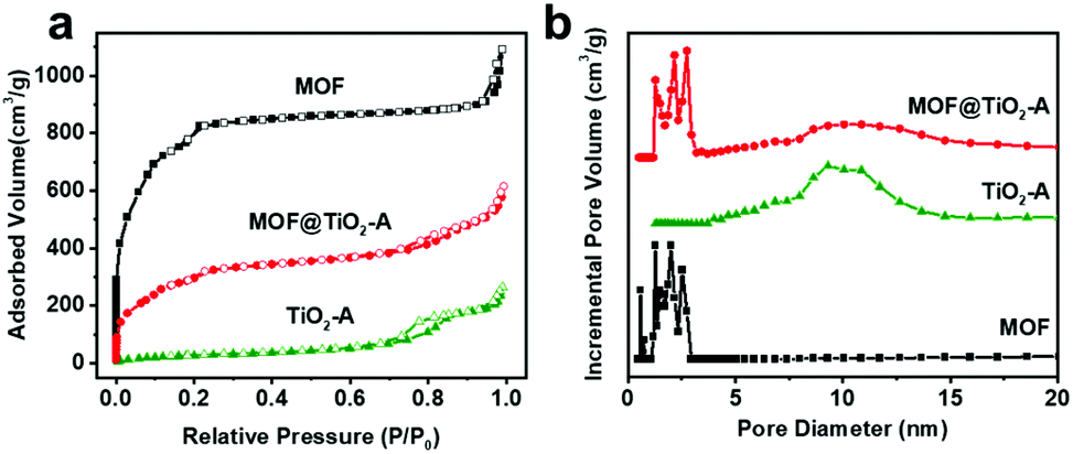 | ||
| Fig. 4 Nitrogen adsorption–desorption isotherms (a) and pore size distribution curves (b) of MOF, TiO2-A and MOF@TiO2-A. | ||
| Sample | S BET (m2 g−1) | Pore size (nm) | V total (cm3 g−1) |
|---|---|---|---|
| MOF | 2823 | 1.1–2.9 | 1.69 |
| TiO2 | 102 | 4.0–16.5 | 0.41 |
| MOF@TiO2-A | 1116 | 1.2–15.5 | 0.95 |
The UV–vis diffuse reflectance spectra (DRS) of MOF, TiO2-A and MOF@TiO2-A are shown in Fig. S6a.† TiO2-A presents strong ultraviolet light absorption with the main peak at 300 nm. MIL-101 presents both ultraviolet and visible light absorption with a narrow peak at 270 nm and two broad peaks at around 440 nm and 590 nm. As expected, MOF@TiO2-A shows combined adsorption signals, including both the strong ultraviolet absorption and the two broad visible light absorptions. The photoluminescence (PL) spectra of various samples were also investigated for comparing their photogenerated charge carrier separation performances. As shown in Fig. S6b,† both TiO2-A and the bare MOF exhibited strong emission bands of fluorescence, indicating the serious recombination of the photogenerated electron–hole pairs which can suppress the photocatalytic activity. Interestingly, MOF@TiO2-A showed much lower intensity of fluorescence emission as compared to the two separated components of MOF and TiO2-A. The reduced recombination loss might be due to the formation of MOF–TiO2 heterojunctions at the core–shell interfaces as already revealed in previously reported literature.35
Zeta potential was also measured to study the surface charge of the hybrid composites. As shown in Fig. S7,† MOF@TiO2-A showed a positive surface charge (+17.5 mV) between that of bare MOF (+35.1 mV) and TiO2-A (+8.9 mV). The moderate positive surface charge of MOF@TiO2-A implies the presence of medium electrostatic interactions with anionic adsorbates, which is in favour of the desorption and degradation of adsorbates. This particular surface charge characteristic together with TiO2 shells may render MOF@TiO2-A an appropriate material for anionic dye adsorption and degradation.
Despite of their excellent adsorption performances towards different kinds of dyes, previous studies have demonstrated that MOFs commonly suffer from serious problems in completely removing adsorbates, which may also cause energy waste or secondary pollution by repeated washing with eluents.19,20,22,23 Here, the integrated MOF@TiO2-A composite is expected to combine the advantages of the MOFs’ high adsorption capacity and TiO2's photodegradation activity.
As a typical azo organic dye, Congo red (CR) dye is one of the most common organic contaminants in industrial effluents. As shown in Fig. S8,† the width, depth and thickness of the CR anion are 2.62, 0.74 and 0.43 nm, respectively, which can be adsorbed by MIL-101 owing to the existence of large mesoporous cages with an internal diameter of 3.4 nm and window aperture of 1.4 by 1.6 nm.52,55 For checking this point, the removal of CR in wastewater was used as a model reaction to evaluate the adsorption and photodegradation performance of the hybrid composite of MOF@TiO2-A.
Initial experimental results indicated that the adsorption–desorption equilibrium of CR over MOF@TiO2-A could be achieved within 50 minutes as shown in Fig. S9.† Hence, the mixture of the hybrid composite and CR were firstly stirred in the dark for 1 h to achieve the adsorption–desorption equilibrium before the lights were turned on. As shown in Fig. 5a, MOF@TiO2-A had much higher adsorption capability (36%) as compared to P25 (3%) and TiO2-A (5%), mainly due to its high BET surface area and larger pore volume; it was lower than that of bare MIL-101 (46%) because of its decreased BET surface area as a result of the introduction of TiO2. After light irradiation, the amount of CR removed over MOF@TiO2-A reached 98% in 2 h without the addition of any oxides (e.g., H2O2), much higher than that of TiO2-A and P25 (48% and 37%, respectively). Although it shows high adsorption capacity, bare MOF can only remove 86% CR dye in 2 h as a consequence of the poor photodegradation capacity of MIL-101. To investigate the photocatalytic performance of MOF@TiO2-A, the photodegradation capacities of the obtained samples were calculated by normalization of the remaining CR concentration after the adsorption process in the dark. As shown in Fig. S10a,† MOF@TiO2-A exhibited the fastest degradation rate compared with P25, TiO2-A and bare MOF. Fig. S10b† reveals that the photocatalytic degradation follows first-order kinetics, which can be fitted by a linear correlation of ln(C0/C) = kt, where k is the apparent first-order rate constant.56 The calculated rate constant of MOF@TiO2-A was significantly higher than those of P25, TiO2-A and bare MOF. These results demonstrate the excellent adsorption capacity and photodegradation efficiency of MOF@TiO2-A.
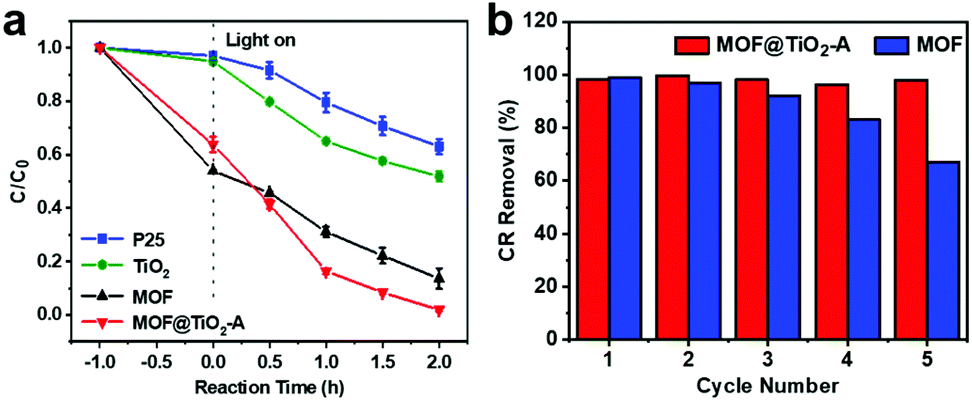 | ||
| Fig. 5 Kinetic traces for CR adsorption and photodegradation in the presence of P25, TiO2, MOF and MOF@TiO2-A (a), and photodegradation stability of recycled MOF and MOF@TiO2-A (b). | ||
MOF@TiO2-A also showed high photostability, with high dye removal efficiency after 5 recycles (up to 98%) (Fig. 5b). Additional characterization results demonstrated that the core–shell structure of MOF@TiO2-A remained well after the photodegradation cycles. As shown in Fig. S11,† the PXRD pattern of the used MOF@TiO2-A is consistent with the fresh sample. In contrast, the framework of bare MOF collapsed after 5 cycles. The N2 adsorption–desorption measurements revealed only a very slight decrease in the specific surface area (0.5%) and the pore volume (8.4%) of the used MOF@TiO2-A in comparison with the fresh one (Fig. S12 and Table S1†). For bare MOF, the specific surface area and pore volume decreased to 40.4% and 39.6%, respectively, which may be responsible for the poor photocatalytic stability of pure MIL-101. Based on the above characterization results, it was proposed that the excellent adsorption/photodegradation performance of MOF@TiO2-A could be mainly attributed to the specific core–shell structure. The relatively high BET surface area and large pore volume, which were inherited from the parent MOF, should contribute to the outstanding adsorption efficiency for CR. The uniform anatase TiO2 shells with piled pores could provide permeable channels for CR molecule adsorption in the MOF cores, and could also provide effective photoactive sites (e.g., the interface structure between MOF and TiO2) that can readily decompose the adsorbed CR molecules. In addition, the CR photodegradation mechanism over MOF@TiO2-A could be hypothesized according to the related literature.18,57 Under UV irradiation, photoexcited electron–hole pairs were generated within the conduction band (CB) and valence band (VB) of TiO2 shells, respectively. The excited electrons oxidize dioxygen to produce superoxide radicals (˙O2−) in the CB, and positive holes reduce water molecules to produce hydroxyl radicals (˙OH) in the VB. The ˙O2− and ˙OH with strong oxidizing ability then oxidize the adjacent CR adsorbed on MOF cores to the mineralized products.
Conclusions
In summary, a multifunctional anatase TiO2-coated MOF composite was obtained via a facile two-step self-assembly approach. The transformation of amorphous TiO2 into the anatase phase could be achieved under a very mild water-assisted crystallization process, which could lead to the formation of uniform anatase TiO2 shells with permeable piled channels. The resultant MOF@TiO2-A core–shell composite shows excellent photodegradation efficiency and cycle stability for anionic dye CR. The existence of an interface structure between the MOF and anatase TiO2 may facilitate the separation of photogenerated electron–hole pairs and initiate the degradation of adjacent CR molecules adsorbed by internal MOF cores, thus playing an efficient synergistic role in the adsorption and photodegradation of dye molecules. Furthermore, anatase TiO2 shells significantly improve the photocatalytic stability of MOF nanocrystals. This simple water-assisted crystallization strategy may provide great opportunities for constructing various photoactive TiO2-coated MOFs composites with high stabilities under mild conditions, and thus may considerably broaden their application in diverse fields.Experimental methods
Chemicals and reagents
All the chemicals were used without further purification: Chromium(III) chloride hexahydrate (CrCl3·6H2O, Alfa Aesar Reagent Company, 98 wt%), 1,4-benzenedicarboxylate (H2BDC, TCI, 98 wt%), tetraisopropyl titanate (TIP, Aladdin, 98%), ammonia solution (NH3·H2O, Tianjin Yongsheng Fine Chemical Company, 25 wt%), Congo red (CR, Tianjin Guangfu Fine Chemical, 98 wt%), ethanol (EtOH, Beijing Chemical Works, GR). Deionized water was obtained from a Millipore Milli-Q plus system.Synthesis of MIL-101
In a typical procedure, 266 mg CrCl3·6H2O (1.0 mmol) and 166 mg H2BDC (1.0 mmol) were dispersed in 10 mL deionized water. After vigorous stirring at room temperature for 3 min, the mixed solution was transferred into a Teflon-lined stainless-steel autoclave and heated at 200 °C for 24 h. On completing the reaction and slowly cooling to room temperature, recrystallized H2BDC was formed in the green solution. The solution was centrifuged at 1000 rpm for 3 min to remove H2BDC. Subsequently, the supernatant green solution containing MIL-101(Cr) was collected by centrifugation at 5000 rpm for 10 min and washed twice with DMF and ethanol. The obtained products were dried in an oven at 80 °C overnight for further use.Synthesis of MOF@TiO2-P
MOF@TiO2-P core–shell nanoparticles were prepared by the Stöber method. Specifically, 80 mg of as-prepared MIL-101(Cr) was homogeneously dispersed in 10 mL ethanol by ultrasonication, followed by the addition of 0.2 mL of ammonia. The mixture was stirred at room temperature for 5 min to form a uniform dispersion. Then, 0.2 mL of TIP was added to the dispersion dropwise under stirring. After 10 min of reaction, the product MOF@TiO2-P core–shell nanoparticles were collected by centrifugation and then washed several times with ethanol.Synthesis of MOF@TiO2-A
MOF@TiO2-A was obtained via the solvothermal treatment of the as-prepared MOF@aTiO2 nanoparticles at a relatively low temperature. Specifically, 100 mg MOF@TiO2-P was homogeneously dispersed in 30 mL deionized water. The dispersion was transferred into a 50 mL Teflon-lined stainless-steel autoclave and heated at 100 °C for 24 h. The obtained product was harvested by centrifuging and washing several times with ethanol, and dried at 80 °C for further use.Photocatalytic measurements
The photocatalytic performance of the as-prepared samples was investigated by the photodegradation of CR. The CR solution with a concentration of 300 ppm was prepared by dissolving the dye in distilled water. For reaction, 5 mg catalyst was added to 40 mL of CR aqueous solution in a 150 mL beaker with a water jacket to keep the temperature of the beaker at 25 °C. The solution was kept in the dark for 1 h under magnetic stirring to reach the adsorption/desorption equilibrium. Afterwards, the reaction vessel was irradiated under simulated solar light (300 W xenon lamp) and the distance between the reaction solution and the light source was 15 cm. During the reaction, 1 mL of sample was withdrawn every 0.5 h. The remaining concentration of CR was detected by UV-visible spectrophotometer at λmax.Characterization
The crystal sizes and morphologies were determined by scanning electron microscopy (SEM) via a JSM-7800F (JEOL) electron microscope, and by transmission electron microscopy (TEM) at 200 kV using a Tecnai F20 electron microscope. The crystallinity and phase purity of the samples were characterized by powder X-ray diffraction (XRD) on a Rigaku D-Max 2550 diffractometer using Cu Kα radiation (λ = 1.5418 Å). Chemical composition was determined via inductively coupled plasma (ICP) analyses carried out on a PerkinElmer Optima 3300 DV ICP instrument. Nitrogen adsorption/desorption measurements were carried out on a Micromeritics 2020 analyzer at 77.35 K after the samples were degassed at 150 °C under vacuum. The pore size distributions were derived from the adsorption branches using the nonlocal density functional theory (NLDFT) approach. X-ray photoelectron spectroscopy (XPS) studies were conducted using a Thermo ESCALAB 250 spectrometer with monochromatized Al Kα excitation. Infrared (IR) spectra of the samples dispersed in KBr pellets were measured on a PerkinElmer Spectrum 430 FT-IR spectrometer. Thermogravimetric (TG) analysis was carried out on a TGA Q500 analyzer in air, with a heating rate of 10 °C min−1. The photoluminescence (PL) spectra of the samples were acquired using a spectrofluorometer (HORIBA Scientific FluoroMax-4). The Zeta potential was measured with a Zetasizer Nano-ZS90 (Malvern Instruments) at 25 °C. A Shimadzu UV-2450 spectrophotometer and a Hitachi U-4100 instrument were used for UV-vis adsorption spectroscopy.Author contributions
M. J. and X. S. conceived the research project. S. B. and M. L. designed and carried out the experiments. Experiments and data analysis were performed by S. B., M. L., P. S., Z. L., X. S. and M. J. The manuscript was drafted by S. B. and revised by X. S. and M. J.Conflicts of interest
There are no conflicts to declare.Acknowledgements
We thank the National Natural Science Foundation of China (grants 21920102005, 21871104, and 22172058), and the 111 Project of China (B17020) for supporting this work.Notes and references
- M. L. Ding, R. W. Flaig, H. L. Jiang and O. M. Yaghi, Carbon capture and conversion using metal-organic frameworks and MOF-based materials, Chem. Soc. Rev., 2019, 48, 2783–2828 RSC.
- M. Eddaoudi, J. Kim, N. Rosi, D. Vodak, J. Wachter, M. O'Keeffe and O. M. Yaghi, Systematic design of pore size and functionality in isoreticular MOFs and their application in methane storage, Science, 2002, 295, 469–472 CrossRef CAS PubMed.
- L. Jiao, Y. Wang, H. L. Jiang and Q. Xu, Metal-organic frameworks as platforms for catalytic applications, Adv. Mater., 2018, 30, 1703663 CrossRef PubMed.
- J. Lee, O. K. Farha, J. Roberts, K. A. Scheidt, S. T. Nguyen and J. T. Hupp, Metal-organic framework materials as catalysts, Chem. Soc. Rev., 2009, 38, 1450–1459 RSC.
- W. P. Lustig, S. Mukherjee, N. D. Rudd, A. V. Desai, J. Li and S. K. Ghosh, Metal-organic frameworks: functional luminescent and photonic materials for sensing applications, Chem. Soc. Rev., 2017, 46, 3242–3285 RSC.
- Z. Xiao, Y. Sun, Y. Bao, Y. Sun, R. Zhou and L. Wang, Two new inorganic–organic hybrid zinc phosphate frameworks and their application in fluorescence sensor and photocatalytic hydrogen evolution, J. Solid State Chem., 2019, 269, 575–579 CrossRef CAS.
- Y. Wang, J. H. Yan, N. C. Wen, H. J. Xiong, S. D. Cai, Q. Y. He, Y. Q. Hu, D. M. Peng, Z. B. Liu and Y. F. Liu, Metal-organic frameworks for stimuli-responsive drug delivery, Biomaterials, 2020, 230, 119619 CrossRef CAS PubMed.
- M. D. Allendorf, C. A. Bauer, R. K. Bhakta and R. J. T. Houk, Luminescent metal-organic frameworks, Chem. Soc. Rev., 2009, 38, 1330–1352 RSC.
- Z. C. Hu, B. J. Deibert and J. Li, Luminescent metal-organic frameworks for chemical sensing and explosive detection, Chem. Soc. Rev., 2014, 43, 5815–5840 RSC.
- H. Furukawa, K. E. Cordova, M. O'Keeffe and O. M. Yaghi, The chemistry and applications of metal-organic frameworks, Science, 2013, 341, 1230444 CrossRef PubMed.
- B. Van de Voorde, B. Bueken, J. Denayer and D. De Vos, Adsorptive separation on metal-organic frameworks in the liquid phase, Chem. Soc. Rev., 2014, 43, 5766–5788 RSC.
- L. Feng, K. Y. Wang, G. S. Day, M. R. Ryder and H. C. Zhou, Destruction of metal-organic frameworks: Positive and negative aspects of stability and lability, Chem. Rev., 2020, 120, 13087–13133 CrossRef CAS PubMed.
- L. Li, X. L. Liu, H. Y. Geng, B. Hu, G. W. Song and Z. S. Xu, A MOF/graphite oxide hybrid (MOF: HKUST-1) material for the adsorption of methylene blue from aqueous solution, J. Mater. Chem. A, 2013, 1, 10292–10299 RSC.
- K. K. Yee, N. Reimer, J. Liu, S. Y. Cheng, S. M. Yiu, J. Weber, N. Stock and Z. T. Xu, Effective mercury sorption by thiol-laced metal-organic frameworks: In strong acid and the vapor phase, J. Am. Chem. Soc., 2013, 135, 7795–7798 CrossRef CAS PubMed.
- Q. Zhang, J. C. Yu, J. F. Cai, L. Zhang, Y. J. Cui, Y. Yang, B. L. Chen and G. D. Qian, A porous Zr-cluster-based cationic metal-organic framework for highly efficient Cr2O72− removal from water, Chem. Commun., 2015, 51, 14732–14734 RSC.
- N. A. Khan, Z. Hasan and S. H. Jhung, Adsorptive removal of hazardous materials using metal-organic frameworks (MOFs): A review, J. Hazard. Mater., 2013, 244, 444–456 CrossRef PubMed.
- E. Haque, J. W. Jun and S. H. Jhung, Adsorptive removal of methyl orange and methylene blue from aqueous solution with a metal-organic framework material, iron terephthalate (MOF-235), J. Hazard. Mater., 2011, 185, 507–511 CrossRef CAS PubMed.
- Z. Xiao, Y. Zhou, X. Xin, Q. Zhang, L. Zhang, R. Wang and D. Sun, Iron(III) porphyrin-based porous material as photocatalyst for highly efficient and selective degradation of Congo red, Macromol. Chem. Phys., 2016, 217, 599–604 CrossRef CAS.
- Y. Zhao, Y. Dong, F. Lu, C. Ju, L. Liu, J. Zhang, B. Zhang and Y. Feng, Coordinative integration of a metal-porphyrinic framework and TiO2nanoparticles for the formation of composite photocatalysts with enhanced visible-light-driven photocatalytic activities, J. Mater. Chem. A, 2017, 5, 15380–15389 RSC.
- X. Zhao, X. H. Bu, T. Wu, S. T. Zheng, L. Wang and P. Y. Feng, Selective anion exchange with nanogated isoreticular positive metal-organic frameworks, Nat. Commun., 2013, 4, 2344 CrossRef PubMed.
- A. X. Yan, S. Yao, Y. G. Li, Z. M. Zhang, Y. Lu, W. L. Chen and E. B. Wang, Incorporating polyoxometalates into a porous MOF greatly improves its selective adsorption of cationic dyes, Chem. – Eur. J., 2014, 20, 6927–6933 CrossRef CAS PubMed.
- L. Yang, Y. L. Liu, C. G. Liu, Y. Fu and F. Ye, A cationic metal-organic framework for dye adsorption and separation based on column-chromatography, J. Mol. Liq., 2020, 300, 112311 CrossRef CAS.
- A. Ghosh and G. Das, Green synthesis of Sn(II)-BDC MOF: Preferential and efficient adsorption of anionic dyes, Microporous Mesoporous Mater., 2020, 297, 110039 CrossRef CAS.
- I. K. Konstantinou and T. A. Albanis, TiO2-assisted photocatalytic degradation of azo dyes in aqueous solution: kinetic and mechanistic investigations - A review, Appl. Catal., B, 2004, 49, 1–14 CrossRef CAS.
- M. Pelaez, N. T. Nolan, S. C. Pillai, M. K. Seery, P. Falaras, A. G. Kontos, P. S. M. Dunlop, J. W. J. Hamilton, J. A. Byrne, K. O'Shea, M. H. Entezari and D. D. Dionysiou, A review on the visible light active titanium dioxide photocatalysts for environmental applications, Appl. Catal., B, 2012, 125, 331–349 CrossRef CAS.
- H. Anwer, A. Mahmood, J. Lee, K. H. Kim, J. W. Park and A. C. K. Yip, Photocatalysts for degradation of dyes in industrial effluents: Opportunities and challenges, Nano Res., 2019, 12, 955–972 CrossRef CAS.
- J. Schneider, M. Matsuoka, M. Takeuchi, J. L. Zhang, Y. Horiuchi, M. Anpo and D. W. Bahnemann, Understanding TiO2 photocatalysis: Mechanisms and materials, Chem. Rev., 2014, 114, 9919–9986 CrossRef CAS PubMed.
- Q. Guo, C. Y. Zhou, Z. B. Ma and X. M. Yang, Fundamentals of TiO2 photocatalysis: Concepts, mechanisms, and challenges, Adv. Mater., 2019, 31, 1901997 CrossRef CAS PubMed.
- S. Chu, H. Li, Q. Ma, H. Li, J. Guo and Q. Zhang, MOF/TBOT-derived hierarchical C-N/Co/Ti composites with effective elemental separation for enhanced oxygen reduction reaction, Appl. Surf. Sci., 2020, 514, 145953 CrossRef CAS.
- Z. Jiang, X. H. Xu, Y. H. Ma, H. S. Cho, D. Ding, C. Wang, J. Wu, P. Oleynikov, M. Jia, J. Cheng, Y. Zhou, O. Terasaki, T. Y. Peng, L. Zan and H. X. Deng, Filling metal-organic framework mesopores with TiO2 for CO2 photoreduction, Nature, 2021, 586, 549–554 CrossRef PubMed.
- X. Y. Li, Y. H. Pi, Q. B. Xia, Z. Li and J. Xiao, TiO2 encapsulated in salicylaldehyde-NH2-MIL-101(Cr) for enhanced visible light-driven photodegradation of MB, Appl. Catal., B, 2016, 191, 192–201 CrossRef CAS.
- H. B. Sheng, D. Y. Chen, N. J. Li, Q. F. Xu, H. Li, J. H. He and J. M. Lu, Urchin-inspired TiO2@MIL-101 double-shell hollow particles: adsorption and highly efficient photocatalytic degradation of hydrogen sulfide, Chem. Mater., 2017, 29, 5612–5616 CrossRef CAS.
- B. X. Zhang, J. L. Zhang, X. N. Tan, D. Shao, J. B. Shi, L. R. Zheng, J. Zhang, G. Y. Yang and B. X. Han, MIL-125-NH2@TiO2 core-shell particles produced by a post-solvothermal route for high-performance photocatalytic H2 production, ACS Appl. Mater. Interfaces, 2018, 10, 16418–16423 CrossRef CAS PubMed.
- F. Fu, G. Cha, N. Denisov, Y. Y. Chen, Y. Zhang and P. Schmuki, Water annealing of TiO2 nanotubes for photocatalysis revisited, ChemElectroChem, 2020, 7, 2792–2796 CrossRef CAS.
- Y. J. Ma, Q. Tang, W. Y. Sun, Z. Y. Yao, W. H. Zhu, T. Li and J. Y. Wang, Assembling ultrafine TiO2 nanoparticles on UiO-66 octahedrons to promote selective photocatalytic conversion of CO2 to CH4 at a low concentration, Appl. Catal., B, 2020, 270, 118856 CrossRef CAS.
- L. Wang, P. X. Jin, S. H. Duan, H. D. She, J. W. Huang and Q. Z. Wang, In situ incorporation of Copper(II) porphyrin functionalized zirconium MOF and TiO2 for efficient photocatalytic CO2 reduction, Sci. Bull., 2019, 64, 926–933 CrossRef CAS.
- Y. M. Zhao, Y. Z. Dong, F. T. Lu, C. G. Ju, L. Liu, J. Zhang, B. Zhang and Y. Q. Feng, Coordinative integration of a metal-porphyrinic framework and TiO2 nanoparticles for the formation of composite photocatalysts with enhanced visible-light-driven photocatalytic activities, J. Mater. Chem. A, 2017, 5, 15380–15389 RSC.
- H. Wang, T. Yu, X. Tan, H. Zhang, P. Li, H. Liu, L. Shi, X. Li and J. Ye, Enhanced photocatalytic oxidation of isopropanol by HKUST-1@TiO2 core–shell structure with ultrathin anatase porous shell: toxic intermediate control, Ind. Eng. Chem. Res., 2016, 55, 8096–8103 CrossRef CAS.
- R. Li, W. Li, C. Jin, Q. He and Y. Wang, Fabrication of ZIF-8@TiO2 micron composite via hydrothermal method with enhanced absorption and photocatalytic activities in tetracycline degradation, J. Alloys Compd., 2020, 825, 154008 CrossRef CAS.
- Y. Y. Li, J. Jiang, Y. Fang, Z. L. Cao, D. Y. Chen, N. J. Li, Q. F. Xu and J. M. Lu, TiO2 nanoparticles anchored onto the metal-organic framework NH2-MIL-88B(Fe) as an adsorptive photocatalyst with enhanced fenton-like degradation of organic pollutants under visible light irradiation, ACS Sustainable Chem. Eng., 2018, 6, 16186–16197 CrossRef CAS.
- R. Li, J. H. Hu, M. S. Deng, H. L. Wang, X. J. Wang, Y. L. Hu, H. L. Jiang, J. Jiang, Q. Zhang, Y. Xie and Y. J. Xiong, Integration of an inorganic semiconductor with a metal-organic framework: A platform for enhanced gaseous photocatalytic Reactions, Adv. Mater., 2014, 26, 4783–4788 CrossRef CAS PubMed.
- M. T. Zhao, K. Yuan, Y. Wang, G. D. Li, J. Guo, L. Gu, W. P. Hu, H. J. Zhao and Z. Y. Tang, Metal-organic frameworks as selectivity regulators for hydrogenation reactions, Nature, 2016, 539, 76–80 CrossRef CAS PubMed.
- B. Y. Guan, L. Yu, J. Li and X. W. Lou, A universal cooperative assembly-directed method for coating of mesoporous TiO2 nanoshells with enhanced lithium storage properties, Sci. Adv., 2016, 2, e1501554 CrossRef PubMed.
- W. Li, A. Elzatahry, D. Aldhayan and D. Y. Zhao, Core-shell structured titanium dioxide nanomaterials for solar energy utilization, Chem. Soc. Rev., 2018, 47, 8203–8237 RSC.
- D. A. Wang, L. F. Liu, F. X. Zhang, K. Tao, E. Pippel and K. Domen, Spontaneous phase and morphology transformations of anodized titania nanotubes induced by water at room temperature, Nano Lett., 2011, 11, 3649–3655 CrossRef CAS PubMed.
- Y. L. Liao, W. X. Que, P. Zhong, J. Zhang and Y. C. He, A facile method to crystallize amorphous anodized TiO2 nanotubes at low temperature, ACS Appl. Mater. Interfaces, 2011, 3, 2800–2804 CrossRef CAS PubMed.
- N. Liu, S. P. Albu, K. Lee, S. So and P. Schmuki, Water annealing and other low temperature treatments of anodic TiO2 nanotubes: A comparison of properties and efficiencies in dye sensitized solar cells and for water splitting, Electrochim. Acta, 2012, 82, 98–102 CrossRef CAS.
- H. B. Yin, Y. Wada, T. Kitamura, S. Kambe, S. Murasawa, H. Mori, T. Sakata and S. Yanagida, Hydrothermal synthesis of nanosized anatase and rutile TiO2 using amorphous phase TiO2, J. Mater. Chem., 2001, 11, 1694–1703 RSC.
- K. Yanagisawa and J. Ovenstone, Crystallization of anatase from amorphous titania using the hydrothermal technique: Effects of starting material and temperature, J. Phys. Chem. B, 1999, 103, 7781–7787 CrossRef CAS.
- Y. Liu, K. Lan, S. S. Li, Y. M. Liu, B. Kong, G. Wang, P. F. Zhang, R. C. Wang, H. L. He, Y. Ling, A. M. Al-Enizi, A. A. Elzatahry, Y. Cao, G. Chen and D. Y. Zhao, Constructing three-dimensional mesoporous bouquet-posy-like TiO2 superstructures with radially oriented mesochannels and single-crystal walls, J. Am. Chem. Soc., 2017, 139, 517–526 CrossRef CAS PubMed.
- N. Chang, H. Zhang, M.-S. Shi, J. Li, W. Shao and H.-T. Wang, Metal-organic framework templated synthesis of TiO2@MIL-101 core-shell architectures for high-efficiency adsorption and photocatalysis, Mater. Lett., 2017, 200, 55–58 CrossRef CAS.
- G. Ferey, C. Mellot-Draznieks, C. Serre, F. Millange, J. Dutour, S. Surble and I. Margiolaki, A chromium terephthalate-based solid with unusually large pore volumes and surface area, Science, 2005, 309, 2040–2042 CrossRef CAS PubMed.
- S. X. Bao, J. Y. Li, B. Y. Guan, M. J. Jia, O. Terasaki and J. H. Yu, A green selective water-etching approach to MOF@mesoporous SiO2 yolk-shell nanoreactors with enhanced catalytic stabilities, Matter, 2020, 3, 498–508 CrossRef.
- N. A. Almeida, P. M. Martins, S. Teixeira, J. A. L. da Silva, V. Sencadas, K. Kuhn, G. Cuniberti, S. Lanceros-Mendez and P. A. A. P. Marques, TiO2/graphene oxide immobilized in P(VDF-TrFE) electrospun membranes with enhanced visible-light-induced photocatalytic performance, J. Mater. Sci., 2016, 51, 6974–6986 CrossRef CAS.
- C. Pelekani and V. L. Snoeyink, A kinetic and equilibrium study of competitive adsorption between atrazine and Congo red dye on activated carbon: The importance of pore size distribution, Carbon, 2001, 39, 25–37 CrossRef CAS.
- P. She, K. Xu, S. Yin, Y. Shang, Q. He, S. Zeng, H. Sun and Z. Liu, Bioinspired self-standing macroporous Au/ZnO sponges for enhanced photocatalysis, J. Colloid Interface Sci., 2018, 514, 40–48 CrossRef CAS PubMed.
- W. K. Jo, S. Kumar, M. A. Isaacs, A. F. Lee and S. Karthikeyan, Cobalt promoted TiO2/GO for the photocatalytic degradation of oxytetracycline and Congo Red, Appl. Catal., B, 2017, 201, 159–168 CrossRef CAS.
Footnotes |
| † Electronic supplementary information (ESI) available. See DOI: https://doi.org/10.1039/d2qi00293k |
| ‡ These authors contributed equally to this work. |
| This journal is © the Partner Organisations 2022 |