Recent progress on metal–organic framework-derived materials for sodium-ion battery anodes
Taiqiang
Chen
a,
Xinjuan
Liu
a,
Lengyuan
Niu
a,
Yinyan
Gong
a,
Can
Li
 a,
Shiqing
Xu
a and
Likun
Pan
 *b
*b
aInstitute of Optoelectronic Materials and Devices, College of Optical and Electronic Technology, College of Materials Science and Engineering, China Jiliang University, Hangzhou 310018, China
bShanghai Key Laboratory of Magnetic Resonance, School of Physics and Electronic Science, East China Normal University, Shanghai 200062, China. E-mail: lkpan@phy.ecnu.edu.cn
First published on 26th November 2019
Abstract
Metal–organic frameworks (MOFs), self-assembled by metal ions and organic ligands via coordination bonds, have been broadly reported as an ideal template or precursor to design and prepare porous nanostructured materials for battery application, due to their high specific surface areas, porous structures and large pore volumes, as well as diverse and tunable structures. Versatile nanostructures, such as carbon, metal oxide, sulfide, selenide and phosphide, have been fabricated from MOFs through pyrolysis or wet chemistry strategies, which exhibit outstanding electrochemical performances for sodium-ion batteries (SIBs) because of well-defined nanostructures inherited from the starting MOFs. In this review, recent progress on MOF-derived materials for SIB anodes is summarized. The preparation methods, structure design strategies and structure–performance relationships are briefly introduced, and some insights into the future development of MOF-derived electrode materials for SIBs are discussed.
1. Introduction
Over the past few decades, vast consumption of fossil fuels has caused severe environmental pollution while, at the same time, the crisis in depletion of fossil fuels has been an added concern. Accordingly, intensive efforts have been made to explore renewable energy sources, such as solar and wind energy. However, most of these renewable energy sources are intermittent, and electrochemical energy storage (EES) is essential for renewable energy systems, to ensure a continuous output. The well-developed lithium-ion batteries (LIBs) have been regarded as a high-performance EES alternative because of their high energy density and longevity, as well as environmental friendliness.1–3 However, with large-scale application of LIBs in the portable electronics and electric vehicle markets, the cost and limitations of lithium resources have become of increasing concern.4–7 As a consequence, sodium-ion batteries (SIBs) that work on the basis of a mechanism similar to LIBs have received much research interest as a low-cost alternative to LIBs for large-scale EES applications, in view of the abundance and low cost of sodium. However, sodium has a much larger ionic radius than lithium (102 pm versus 76 pm), leading to sluggish kinetics and large structure changes in the electrode materials during sodiation/desodiation cycles. Therefore, the electrode materials for SIBs need to have well-designed structures to achieve high electrochemical performance.Recently, metal–organic frameworks (MOFs), self-assembled by metal-containing nodes and organic linkers via coordination bonds, have been widely used as a significant candidate in fields such as gas adsorption and separation, catalysis, as well as energy conversion and storage, due to their high specific surface area (SSA), porous structure and large pore volume.8–11 MOFs feature topologically diverse and aesthetically pleasing structures, stemming from their underlying topological nets. The combination of the metal-containing nodes and organic linkers provides MOFs with endless structural possibilities. The functionality of a given structure, with controlled connectivity of the vertices, offers even more intriguing properties for MOFs. Up to now, more than 20![[thin space (1/6-em)]](https://www.rsc.org/images/entities/char_2009.gif) 000 MOFs have been reported, showing diverse structures with tunable porosity and controllable functional properties due to their multiple forms in metal-containing nodes (such as metal ions) and organic ligands.12
000 MOFs have been reported, showing diverse structures with tunable porosity and controllable functional properties due to their multiple forms in metal-containing nodes (such as metal ions) and organic ligands.12
Normally, MOFs are not able to be used directly as electrode materials for batteries because of their poor electronic conductivity. Nevertheless, they have been widely reported as an ideal template or precursor to design and prepare porous nanostructured materials for batteries, by taking advantage of their designable framework configuration and diverse morphologies.13,14 During such synthetic processes, the uniformly distributed metal ions and organic ligands at the atomic level in MOFs are favourable for producing nanosized metal compound particles and guaranteeing uniform distribution of the nanosized particles within the organic ligand derivatives, leading to the desired nanostructures. Moreover, the open pore structure and long-range ordering of MOFs can provide a fast and facile channel for incoming and leaving small molecules and ions in the transformation process, easily producing porous nanostructures that retain the basic framework of the starting MOFs. Due to the multiple forms for metal-containing nodes and organic ligands, various metal compounds, carbonaceous materials and their composites with desired porous nanostructures can be conveniently designed and fabricated from MOFs. In a frequently used strategy, MOFs are pyrolyzed in an inert atmosphere to prepare a metal compound/carbon composite. During pyrolysis, the metal ions and organic ligands inside the MOF crystals can be translated into metal compounds and carbon, respectively, without long-range atomic migration, as a result of their periodical atomic-level alignment. This leads to the formation of well-defined metal compound nanoparticles embedded in a porous carbon matrix structure, which partially inherits the basic porous framework of the starting MOF. If the pyrolysis is carried out below the thermal reduction temperature of the metal, metal oxides are fabricated in the pyrolyzed product, otherwise the emergence of metallic species occurs.15,16 Pure metal oxides are prepared from MOFs if the pyrolysis is carried out in air,17,18 and pure carbon materials are obtained by high-temperature evaporation or successive acid etching to remove the residual metal species.19,20 In addition, if sulfur, selenium or phosphorus resources are present in the pyrolysis, the corresponding metal sulfide,21,22 selenide23,24 or phosphide25,26 can be conveniently synthesized. In addition, MOFs can also be used as resources (with template effects) for metal species for the preparation of diverse nanostructures in wet chemistry methods. In such a strategy, ion exchange between the organic ligands and the desired anionic species takes place27,28 and, in some cases, the MOFs are even completely dissolved,29,30 producing versatile nanostructures.
It should be pointed out that the structure, morphology and composition of the MOFs, as well as the fabrication processes and conditions, will influence the structure, morphology and composition of the final products and, in turn, the electrochemical performance. Due to the multiple forms of MOFs, various electrode materials with colourful structures have been fabricated from MOFs. This review summarizes recent progress on MOF-derived materials for SIBs, focusing on MOF-derived anode materials. Specifically, progress on MOF-derived carbon, oxide, sulfide, selenide and phosphide, as well as some other materials, is reviewed from a materials science perspective.
2. Carbon
Carbon materials are the most widely used anode materials for LIBs due to their low potential, high capacity, good stability, abundance, and low cost.31,32 For the same reasons, carbon anode materials are also among the most promising choices for SIBs.33–35 However, it is well recognized that sodium can barely intercalate into the graphite that is the commercial anode material in LIBs, due to unfavourable thermodynamics. Accordingly, non-graphitic or hard carbon has been intensively studied and developed for SIBs. The house of cards model is widely used as the model structure for hard carbon in studying the alkali-ion storage mechanism.36 It is believed that hard carbon consists of randomly distributed turbostratic and cross-linked domains with graphene nanosheets and expanded interlayer spacing, as well as micropores formed between these microstructures. Sodium storage mechanisms, including: (1) intercalation between graphene sheets in turbostratic graphitic structures; (2) storage in closed micropores; and (3) surface and defect absorption, have been demonstrated for hard carbon.37 Therefore, improvements in microstructure, porosity and morphology are crucial for high-performance, hard-carbon anode materials. These factors are very sensitive to the carbon precursor and the preparation process, such as the calcination temperature. Because of their versatility in composition, pore structure and morphology, MOFs have exhibited high promise as colourful precursors for hard-carbon anode materials for SIBs.Fig. 1 is a schematic illustration of the synthetic route for MOF-derived carbons. When MOFs are pyrolyzed in an inert atmosphere, in situ formation of carbon species can be realized through carbonization of the organic ligands in the MOF scaffolds.38,39 High-temperature evaporation or successive acid etching removes the residual metal species, producing pure carbon materials.40 Under well-controlled conditions, the obtained carbon inherits a similar morphology to that of the MOF precursor, in spite of the high-temperature pyrolysis. The different types of MOF precursors play an important role in determining the structure and performance of the final product. Microporous carbon with an SSA of 1251 m2 g−1 and homogeneous pore size of 0.5 nm was obtained through direct pyrolysis of ZIF-8 (Zn(2-methylimidazole)2) at 930 °C by Qu et al.41 The as-prepared carbon showed a reversible sodium storage capacity of 164 mA h g−1 with good cycling stability over 50 cycles. Based on MOF-5 (Zn4O(1,4-benzodicarboxylate)3), Ji's group prepared a cube-shaped porous carbon with abundant micro/mesopores and a large SSA of 2316 m2 g−1 at a pyrolysis temperature of 1000 °C.20 Because the abundant micro/mesopores give a substantial contribution to capacity via a surface-based ion storage mechanism, this porous carbon presented a reversible sodium storage capacity of 326 mA h g−1 and maintained a stable capacity over 5000 cycles, showing much better performance than the ZIF-8-derived carbon. Recently, Ingersoll et al. compared the structures and performances of ZIF-8- and MOF-5-derived carbons in detail.42 They found that starting MOFs with larger, more open pore structures would probably be beneficial for improving the capacity and rate performance of the derived carbon, due to improved charge transfer and sodium-ion transportation. In addition, 1,3,5-benzenetricarboxylic acid (BTC)-based MOFs43,44 and ZIF-6745 (Co(2-methylimidazole)4) have also been reported to be good precursors for the preparation of high-performance carbon materials for SIBs.
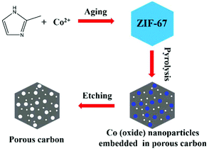 | ||
| Fig. 1 Schematic illustration of the synthetic route for MOF-derived carbon using ZIF-67 as an example. | ||
The impact of pyrolysis temperature on the structure and performance of MOF-derived carbons was studied by Gu et al.45 and Liu et al.46 based on ZIF-67 and ZIF-8, respectively. With elevation of the temperature of pyrolysis, from 600 to 900 °C, similar trends of increase in degree of carbonization and SSA were demonstrated, but a decrease in doped nitrogen content was observed, as shown in Fig. 2a and b. In both studies, the carbons with developed porosity that were pyrolyzed at a relatively low temperature exhibited the highest reversible sodium storage capacity (Fig. 2c and d ). This may indicate that a large SSA is not essential for a high-performance carbon anode material. Nevertheless, a poorly developed graphitic structure, with a high degree of disorder or defects (such as nitrogen doping), is beneficial for sodium storage. The ZIF-8-derived carbon pyrolyzed at 700 °C showed the highest reversible capacity of more than 300 mA h g−1 after 500 cycles at a current density of 0.5 A g−1, as well as good cycle stability and rate capability.46 Heteroatom doping, other than with nitrogen, has also been reported to alter the microstructure of MOF-derived carbons. Zhang's group prepared sulfur-doped mesoporous carbons through pyrolysis of MOF-5 using sulfur powders as the sulfur source.47 Sulfur doping (mainly in the form of C–S–C and C![[double bond, length as m-dash]](https://www.rsc.org/images/entities/char_e001.gif) S) could enlarge the interlayer spacing of carbon and contribute more active sites for sodium storage. As a result, the sulfur-doped mesoporous carbon exhibited an improved reversible capacity of 270 mA h g−1 at 100 mA g−1 and long-term cycling stability (80.5% capacity retention after 500 cycles), as well as outstanding rate capability (90 mA h g−1 at 3.2 Ag−1) in SIBs.
S) could enlarge the interlayer spacing of carbon and contribute more active sites for sodium storage. As a result, the sulfur-doped mesoporous carbon exhibited an improved reversible capacity of 270 mA h g−1 at 100 mA g−1 and long-term cycling stability (80.5% capacity retention after 500 cycles), as well as outstanding rate capability (90 mA h g−1 at 3.2 Ag−1) in SIBs.
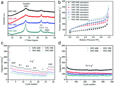 | ||
| Fig. 2 (a) X-ray diffraction (XRD), (b) N2 sorption isotherms, (c) rate capability and (d) cycling performance of the ZIF-67-derived carbons pyrolyzed at temperatures from 600 to 900 °C. Reproduced from ref. 45 with permission from John Wiley and Sons. | ||
Development of a desirable morphology is important for advanced carbon anode materials. Ji's group assembled one-dimensional Mn-MOFs into three-dimensional (3D) hollow spheres by regulating the amount of poly(vinylpyrrolidone) (PVP), and obtained 3D hollow porous carbon microspheres via subsequent carbonization and acid treatment (Fig. 3).43 When utilized as anode materials for SIBs, the carbon microspheres delivered a high capacity (314 mA h g−1 at 0.1 A g−1), good rate capability (113 mA h g−1 at 5 A g−1) and cycling stability. The outstanding electrochemical performance was attributed to the 3D hollow porous microsphere structure, which enhances the mechanical stability, buffers the volume expansion, and accelerates the transport of Na+ and electrons. Recently, Liu et al.19 developed N-rich porous carbon nanosheets derived from two-dimensional (2D) Zn-hexamine MOF nanosheets for SIBs. A high capacity (318 mA h g−1 at 0.1 A g−1), ultrafast capability (194 mA h g−1 at 10 A g−1) and good long-term cycling stability (76.9% capacity retention after 1000 cycles) were delivered by these as-prepared carbon nanosheets. The prominent high rate performance is explained by a major capacitive effect, as revealed by the electrochemical kinetics investigation based on cyclic voltammetry (CV) at different scan rates. Moreover, wrinkled carbon foils48 and accordion-like nanoporous carbon49 have also been reported to show superb electrochemical performance in SIBs.
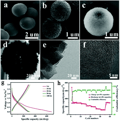 | ||
| Fig. 3 (a–c) Scanning electron microscopy (SEM) images, (d and e) transmission electron microscopy (TEM) images, and (f) high-resolution TEM (HRTEM) image of the 3D hollow porous carbon microspheres. (g) The discharge–charge profiles under different cycle numbers and (h) the rate capability of the carbon microspheres. Reproduced from ref. 43 with permission from the Royal Society of Chemistry. | ||
Constructing carbon-based composites has provided an opportunity to achieve synergistic effects between different components.39 Cobalt-embedded hierarchical carbon hybrids (CoCHs) were synthesized through the stereoselective assembly of Co-MOFs on polyacrylonitrile (PAN) accompanied by catalytic pyrolysis, as illustrated in Fig. 4.39 The hybrids consisted of free-standing, PAN-derived, interconnected carbon networks decorated with porous multiwall carbon nanotubes (MWCNTs)/CoCH. The MWCNTs were produced catalytically by the in situ-formed Co nanoparticles during carbonization. Profiting from the favourable effects of enhanced electrical conductivity, as well as self-supported features, such carbon hybrids exhibited a high specific capacity of 220 mA h g−1 and superior stability in SIBs. Chen et al. reported the preparation of self-assembled N-doped porous carbon nanocomposites via the pyrolysis of ZIF-8/carbon composites grown on various carbon frameworks (i.e. one-dimensional carbon nanotubes (CNTs) and 2D graphene oxide (GO)).50 They found that the electrochemical performance of the carbon nanocomposite using both CNTs and graphene substrates was enhanced compared with that of bare N-doped porous carbon (NPC) or nanocomposite using only one substrate. Due to the synergistic effect of NPC, CNTs and graphene, the optimized carbon nanocomposite delivered a high reversible capacity of 315 mA h g−1 and maintained a good capacity retention of 80% after 300 cycles. Moreover, MOF-derived microporous carbon has also been regarded as an ideal template for confining nanosized amorphous red P in SIBs.51
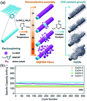 | ||
| Fig. 4 (a) Preparation of hierarchical CoCHs derived from M(MOFs)@PAN fibers. (b) Cycle performance of CoCHs in SIBs at 100 mA g−1. Reproduced from ref. 39 with permission from John Wiley and Sons. | ||
3. Metal oxide
3.1 Titanium dioxide (TiO2)
Titanium dioxide (TiO2) is considered to be a particularly attractive anode material for SIBs due to its excellent stability, abundance, non-toxicity and environmental friendliness. TiO2 presents in the form of versatile polymorphs, among which anatase, rutile and amorphous structure are the most commonly reported. The sodium storage mechanism of TiO2 is still under investigation,52 although mechanisms including insertion, conversion reactions, and pseudocapacitance have been reported in the literature. The crystallinity, particle size, ionic/electronic conductivity and operating conditions are the key factors that affect the differences in the sodiation/desodiation mechanism. Because of the sluggish sodium-ion diffusion in TiO2, the kinetics of insertion and conversion reactions is rather poor.53 Therefore, it is important to design nanostructures together with a porous texture to improve the kinetics. In these structures, the pseudocapacitance mechanism would play a major role, due to the high surface to volume ratio.54,55Taking advantage of MOFs as precursors, porous TiO2 nanostructures can be conveniently prepared.18,56 In a typical process, terephthalic acid and tetra-n-butyl titanate (Ti(OC4H9)4) in a mixed solvent of dimethylformamide (DMF) and methanol react under solvothermal conditions to give MIL-125(Ti). Subsequent calcination of the MIL-125(Ti) in air burns out the organic ligand and produces porous TiO2 with a morphology inherited from the MOF precursor. A cake-like, porous TiO2 derived from MIL-125 prepared by Pan's group exhibited a high SSA of 96 m2 g−1 and fine particle size of ∼20 nm.18 This porous structure favours electrolyte permeation and shortens the sodium-ion diffusion length. Thus, a high capacity of 250 mA h g−1 and good rate capability (117 mA h g−1 at 4.0 A g−1) were achieved. Moreover, this cake-like TiO2 showed excellent cycle stability, with negligible capacity decay over 2500 cycles. It should be pointed out that the calcination temperature is an extremely important factor that affects the structure and electrochemical performance of the materials. With increase in heating temperature from 380 to 500 °C, the TiO2 particles sintered and their size increased, resulting in decreased SSA and poor electrochemical performance.
When the calcination of Ti-MOF is carried out in an inert atmosphere, such as N2 or Ar, the organic ligands are carbonized and the in situ-formed TiO2 nanoparticles are encapsulated by the carbon to construct a TiO2/carbon composite. This carbon matrix could greatly enhance the electrochemical performance of TiO2 due to increased SSA and confined particle size, as well as improved conductivity.57 Ji's group reported a carbon-coated rutile TiO2 through in situ-pyrolysis of Ti-MOF.58 They found that the as-prepared carbon-coated composite showed a larger specific surface area (245 m2 g−1versus 12.8 m2 g−1) and better electronic conductivity compared with pure TiO2. In addition, the carbon coating could effectively prevent aggregation of the TiO2 nanoparticles, accelerate the mass transfer of Na+ and speed up the charge transfer rate. Thus, the capacity and rate capability, as well as cycle performance, of the coated TiO2 were improved.
The nature of carbon in the TiO2/carbon composite is an important aspect determining the performance of the composite. Heteroatom doping and the introduction of an additional carbon matrix, such as graphene, have been reported to further improve the composite. Zhao et al. fabricated a TiO2/nitrogen-doped carbon (TiO2/NC) composite by simply substituting the organic ligand of terephthalic acid with 2-amino terephthalic acid, to synthesize NH2-MIL-125(Ti) as the precursor.59 They studied the influence of calcination temperature and found that elevating the temperature increased the degree of carbonization, the particle size of TiO2, the content of anatase and the SSA, while decreasing the content of doped nitrogen, as displayed in Fig. 5 and 6. The sample calcined at 600 °C exhibited the best sodium storage performance in terms of capacity, rate capability and cycle stability because of its desirable anatase structure, small TiO2 particle size and high nitrogen-doping content. Sulfur doping of the carbon matrix is also an effective way to enhance the performance of the TiO2/carbon composite. It has been demonstrated that sulfur doped in porous carbon not only improves the charge transfer, but also increases the sodium storage capacity due to its electrochemical reactivity with sodium ions.60 In a work reported by Zhang et al., reduced graphene oxide (RGO) was introduced, additionally, to the TiO2/carbon composite by utilizing a GO/MOF composite as precursor.61 It is believed that the wrapping of RGO could improve the electronic conductivity, and construct a unique porous structure with iso-oriented TiO2 nanoparticles, leading to enhanced cycling stability and rate performance.
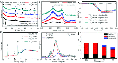 | ||
| Fig. 5 (a) XRD patterns of NH2-MIL-125(Ti) precursor and four TiO2/NC nanocomposites. (b) Raman spectra, (c) thermal gravimetric analysis curves and (d) X-ray photoelectron spectroscopy (XPS) survey spectra of four TiO2/NC nanocomposites. (e) High-resolution N 1s spectrum of TiO2/NC-800 (800 represents the calcination temperature, which is the same for TiO2/NC-500, etc.). (f) Atomic contents of various nitrogen-doping types for the TiO2/NC nanocomposites obtained at different temperatures. Reproduced from ref. 59 with permission from John Wiley and Sons. | ||
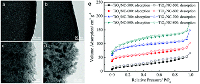 | ||
| Fig. 6 TEM images of (a) TiO2/NC-500, (b) TiO2/NC-600, (c) TiO2/NC-700, (d) TiO2/NC-800 and (e) N2 sorption isotherms of the four TiO2/NC nanocomposites prepared at different temperatures. Reproduced from ref. 59 with permission from John Wiley and Sons. | ||
Defect chemistry is another promising strategy to further enhance the performance of TiO2. It has been proven that introducing Ti3+ species or oxygen vacancies in TiO2 can significantly narrow the band gap and facilitate electronic and ionic conductivity.62,63 He et al. synthesized defect-rich TiO2/carbon composites by pyrolysis of the MIL-125(Ti) precursor with magnesium reduction.55 The as-prepared composite consists of TiO2 nanocrystals with an average size of 5 nm that are well dispersed in the carbon matrix. The presence of rich defects and Ti3+ species in TiO2 was confirmed by XPS and electron spin resonance. The defect-rich TiO2/carbon composite exhibited a high reversible capacity of 330 mA h g−1 (compared with a capacity of 261 mA h g−1 for the control sample) and long-term cycling stability, with negligible capacity decay over 5000 cycles in SIBs, as shown in Fig. 7. In-depth electrochemical kinetics investigations revealed a major pseudocapacitive process for the composites, which was largely enlarged by introducing Ti3+ species and oxygen vacancies onto the surface as well as into the bulk of TiO2. Recently, Xu et al. presented a Co-doped TiO2/carbon composite by using Co-doped Ti-MOFs as precursor.54 They demonstrated that doping of Co2+ in TiO2 lead to substitution of Ti4+, decreased the c-axis and resulted in oxygen vacancies. These oxygen vacancies greatly improved the electrical conductivity and electrochemical performance of the composite.
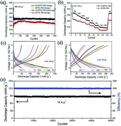 | ||
| Fig. 7 (a) Cycling performance of MTO-700 (regular TiO2/carbon) and D-MTO-700 (defect-rich TiO2/carbon). (b) Rate performance of MTO-700 and D-MTO-700 at various current densities. Charge–discharge curves of MTO-700 (c) and D-MTO-700 (d) at various current densities. (e) Cycling performance of D-MTO-700. Reprinted from ref. 55, Copyright (2017), with permission from Elsevier. | ||
3.2 Cobalt-based oxides
Relying on a conversion mechanism, cobalt-based oxides (such as CoO and Co3O4) are widely considered to be promising anode materials for SIBs because of their simple synthesis, environmental friendliness and high specific capacity. However, they often suffer from poor rate capability and unsatisfactory cycle performance due to inferior electronic conductivity, poor ion transport kinetics and large volume changes during sodium insertion/extraction processes.64 Intensive efforts have been made to address these problems. Strategies such as reducing particle size, constructing porous structures and introducing carbon-conducting supports have been proposed.64,65 Interestingly, MOFs have been widely accepted as an ideal template to construct such a desirable porous structure with ultrafine particles, benefiting from their versatile porosity and long-range ordering of metal ions and organic ligands. In this structure, the nanoscale particle size can shorten the diffusion length of ions and electrons, the porous structure is beneficial to electrolyte permeation and volume change buffering, and the carbon support can enhance the electrical conductivity of the composite and alleviate structure change upon cycling.Up to now, porous structures with various morphologies derived from versatile MOFs have been reported. Li et al. obtained shale-like Co3O4 with layered structures composed of ultrafine nanocrystallites (∼10 nm) from a layered cobalt-based metal–organic compound.17 The unique structure donates an extremely short ion-diffusion pathway and rich porosity. As a result, the as-prepared Co3O4 showed decent electrochemical performance in SIBs, with capacities of 380 and 154 mA h g−1 at 50 and 5000 mA g−1, respectively. Based on the interface separation resulting from a multi-step calcination in Ar and air, Mai's group successfully synthesized porous yolk–shell Co3O4/carbon dodecahedra from ZIF-67.66 Because the yolk–shell structure could alleviate the volume expansion during lithiation or sodiation, and the carbon matrix is beneficial to the electrical conductivity of the materials, the composite showed high capacity, excellent rate capability and good cycling stability in both LIBs and SIBs. High capacities of 608 and 269 mA h g−1 at 0.2 and 2 A g−1, respectively, were achieved in SIBs. A flower-like Co3O4/carbon composite derived from Co2+ and nicotinic acid-assembled MOFs was also reported to be a high-performance anode, profiting from its unique flower-like structure.65
It is well known that Co is a good catalyst for the catalytic growth of CNTs. If the pyrolysis temperature of Co-MOFs is elevated to an adequately high value, and an appropriate reductive atmosphere is constructed, CNTs can grow in the product using the decomposed organic ligands as a carbon source. Pang et al. pyrolyzed lamellar Co-MOFs at 800 °C in a mixed atmosphere of Ar and H2, and obtained a 2D CoO/nitrogen-doped CNT (CoO-NCNT) composite.67 The cobalt oxide particles were encapsulated and remained at the apical position of the CNTs, as presented in Fig. 8. Such a structure could guarantee superior conductivity and relieve the volume change of the CoO during charge–discharge. Moreover, CNTs intertwined together could construct an effective conductive network favouring ion transfer. The composite delivered a capacity of 561 mA h g−1 at 200 mA g−1, and retained a capacity retention ratio of 80.56% after 300 cycles in SIBs, showing great potential for lithium/sodium storage.
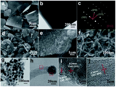 | ||
| Fig. 8 (a) SEM image, (b) TEM image, and (c) selected area electron diffraction analysis of Co-MOFs. (d–f) SEM images of CoO-NCNTs at different magnifications. (g and h) TEM and (i and j) HRTEM images of CoO-NCNTs corresponding to the two marked regions in (h). Reproduced from ref. 67 with permission from the Royal Society of Chemistry. | ||
Heteroatom (such as Ni, Zn and Ti) doping has been reported to enhance the electrochemical performance of cobalt-based oxides. Doped oxides can be easily synthesized via the pyrolysis of heteroatom-doped MOFs that are prepared through bimetallic MOFs or ion exchange. The successful doping is usually confirmed by XRD (tiny lattice distortion) and XPS (slight shift in the binding energies of Co). In work reported by Kaneti et al., Ni doping was supposed to introduce defect sites into the atomic structure of CoO via partial substitution.16 These defects are considered to enhance the conductivity of the cobalt oxide (CoO) component and, hence, the overall hybrid material. Ni and Zn doping was also reported to provide more active sites for lithium and sodium storage by Han et al.68,69 In another work, Li et al. found that Ti doping could decrease the size of CoO, enhance the specific surface area of the Ti-doped CoO@carbon composite and, as a result, improve the pseudocapacitance contribution.15 However, it remains unclear how the doped elements function during the conversion reaction. Currently, any conclusions that emphasize a doping enhancement would be uncertain. Adequate and well-controlled studies are still needed to clarify the effect of doping due to the complexity of the nanocomposite system.
3.3 Other unary metal oxides
Many other unary transition metal oxides, such copper-, iron-, nickel- and manganese-based oxides, have also been found to be electrochemically active in SIBs. They rely on a conversion mechanism similar to the cobalt-based oxides, and suffer from inferior electronic conductivity, poor ion transport kinetics and large volume changes. The MOF-derived strategy has been adopted as an intriguing way to construct desirable structures for these materials as well. Copper-based oxides, such as CuO and Cu2O, have received attention because of their abundance, chemical stability and non-toxicity.70 Using Cu-MOFs ([Cu3(BTC)2]n) as the template, Pan et al. successfully prepared porous CuO/Cu2O composite hollow octahedra (CHO) that consist of nanoparticles with a size of tens of nanometers, and their influence on calcination temperature was studied.71 It was found that the porous structure of the octahedra gradually collapsed and the electrochemical performance declined as the calcination temperature increased, as shown in Fig. 9. The sample calcinated at 300 °C delivered a maximum reversible capacity of 415 mA h g−1 after 50 cycles at 50 mA g−1 with excellent cycling stability and good rate capability in SIBs. With the help of GO, the same group demonstrated a porous CuO/RGO composite derived from Cu-MOFs/GO.72 The sodium storage capacity of this composite was elevated to 503 mA h g−1 at 100 mA g−1 and a capacity of 348 mA h g−1 could be retained even at 2 A g−1, showing decent rate capability. Kim et al. presented a CuO/Cu2O in a porous carbon composite derived from Cu-MOFs via a programed thermal transformation process in nitrogen and air, successively. The composite exhibited a capacity of 303 mA h g−1 after 200 cycles at 50 mA g−1 in SIBs. The good cycling stability was attributed to the synergistic effect of the CuO and Cu2O micronanoparticles and highly graphitized porous carbon formed by catalytic graphitization of the Cu nanoparticles.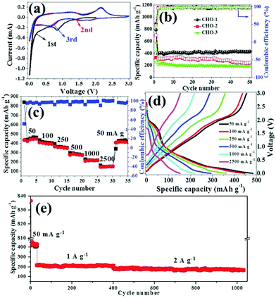 | ||
| Fig. 9 (a) CV curves of CHO-1 and (b) cycling performance of CHO electrodes at a current density of 50 mA g−1. (c) Rate capabilities at different current densities, (d) typical discharge–charge curves at different current densities and (e) long cycling performance of CHO-1. The CHO samples obtained from pyrolysis of MOFs at 300, 350 and 400 °C are denoted as CHO-1, CHO-2 and CHO-3, respectively. Reproduced from ref. 71 with permission from the Royal Society of Chemistry. | ||
Taking advantage of MIL-88-Fe-NH2 as the template and GO as the backbone, Qi et al. reported a composite composed of nitrogen-doped graphene (GN)-supported raspberry-like microstructures.73 The raspberry-like microstructures (Fe3O4 QD@C-GN) were embedded with carbon-coated Fe3O4 quantum dots, as shown in Fig. 10. Due to the short diffusion length and integrated hierarchical conductive network, this composite favours a surface-induced process. Therefore, it exhibited a high capacity (680 mA h g−1 at 0.2 A g−1), excellent rate capability (161 mA h g−1 at 10 A g−1) and good cycling performance. Using PVP as the stabilizing agent, Zou et al. synthesized Ni-MOFs with a hierarchical, hollow, ball-in-ball structure using nickel nitrate and trimesic acid as the metal source and organic ligand, respectively.74 These Ni-MOFs were transformed intact to a hierarchical hollow NiO/Ni/graphene composite after successive carbonization and oxidation. Graphene was believed to be catalytically produced by the in situ-formed Ni nanoparticles during the carbonization. The composite provided a high reversible capacity (483 mA h g−1 at 0.2 A g−1), good cycling stability (capacity fading rate of 0.2% per cycle over 200 cycles) and rate performance (207 mA h g−1 at 2 A g−1). The authors ascribed the good electrochemical performance to the well-designed hollow structure, which not only mitigates the volume expansion of NiO during repeated cycles, but also provides a continuous highly conductive graphene matrix. Such a graphene matrix could facilitate the fast charge transfer and form a stable solid electrolyte interphase (SEI) layer. In addition, porous MnO@C nanorods were also reported to be synthesized simply by annealing Mn-MOFs, and they showed superb sodium storage performance.75
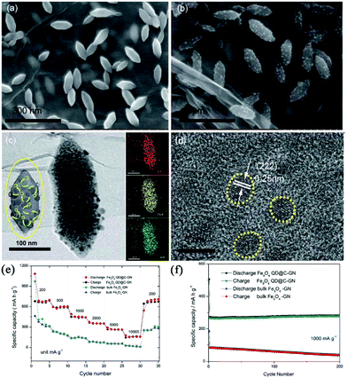 | ||
| Fig. 10 (a) SEM image of the MOF precursors. (b) SEM image of the final raspberry-like Fe3O4 QD@C-GN. (c) TEM images of the final raspberry-like Fe3O4 QD@C-GN and the corresponding elemental mapping images. (d) HRTEM image of Fe3O4 QD@C-GN. (e) Comparative rate capability and (f) cycle performance of Fe3O4 QD@C-GN and bulk Fe3O4-GN. Reproduced from ref. 73 with permission from the Royal Society of Chemistry. | ||
In addition to the aforementioned conversion-type oxides, MOFs have inevitably found application in other types of oxides, such intercalation-based vanadium oxides76,77 and alloy-aided tin dioxide78 and zinc oxide.79 A porous shuttle-like V2O3/C composite was reported by Liang's group via the calcination of MIL-88B(V) in Ar.76 The V2O3 had an inherent layered structure with metallic behaviour, which could be preserved after sodium insertion. Hence, assisted by the uniform carbon coating, the composite exhibited outstanding electrochemical performance with high capacity (417 mA h g−1 at 50 mA g−1), good rate capability (149 mA h g−1 at 2 A g−1) and cycling stability (capacity fading rate of 0.032% per cycle over 1000 cycles). Kong et al. demonstrated that vanadium oxide/porous carbon nanorods (VOx/PCs) with orderly slit-like 2D pores could be derived from MOFs and showed high rate capability and ultralong cycling life for sodium storage.77
3.4 Binary metal oxides
Recently, binary metal oxides have received widespread attention as anode materials for SIBs due to their variability of chemical composition. Notably, cobalt nickel oxide (NiCo2O4) has been viewed as a promising, less expensive and scalable alternative for high-performance cobalt-based oxides due to the abundance, low cost and environmental friendliness of Ni.80 According to previous work,80,81 the sodium storage mechanism of NiCo2O4 can be expressed as follows:| NiCo2O4 + 8Na+ + 8e− → Ni + 2Co + 4Na2O | (1) |
| Ni + Na2O ⇄ NiO + 2Na+ + 2e− | (2) |
| Co + Na2O ⇄ CoO + 2Na+ + 2e− | (3) |
| CoO + 1/3Na2O ⇄ 1/3Co3O4 + 2/3Na+ + 2e− | (4) |
After the first discharge, the sodium storage mechanism is mainly based on two independent conversion reactions of the corresponding component unary metal oxide. These conversion reactions suffer from poor kinetics, as is the case for cobalt-based oxides. Accordingly, MOFs are applied to construct a porous nanostructure for this binary metal oxide. Chen et al. synthesized hollow porous NiCo2O4 nanoboxes based on the reaction between ZIF-67 and Ni ions, and found that this NiCo2O4 could achieve a high reversible capacity of 531 mA h g−1 in SIBs.82 Recently, Zhang et al. reported the preparation of hierarchical NiCo2O4/NiO/carbon nanofibers through the in situ growth of Co/Ni-MOFs on a polymer (Co/Ni) fiber precursor.83 When used as anode materials in SIBs, the as-prepared composite displayed a high capacity (495 mA h g−1 at 0.1 A g−1) and outstanding rate capability (168 mA h g−1 at 5 A g−1), which were better than for the Co3O4/carbon and NiO/carbon nanofibers. In addition, a cobalt-based binary metal oxide, CoSnO3, was reported to be directly modified by an in situ construction and successive pyrolysis of the Co-MOF method.84 The treatment introduced conductive N-rich carbon, improved the porosity and, thus, enhanced the electrochemical performance of CoSnO3 in SIBs.
Fe-Based binary oxides (such as MgFe2O4, CoFe2O4 and MnFe2O4) have also received attention as anode materials for SIBs due to their low cost, high capacity and rich redox reactions.85,86 Using non-toxic and low-cost Prussian blue MOFs as templates, porous CoFe2O4 nanocubes with an ordered mesoporous structure and high SSA of 106.8 m2 g−1 were prepared by Zhang et al.86 The as-prepared nanocubes exhibited a high reversible capacity of 360 mA h g−1 after 50 cycles at 50 mA g−1, as well as good rate capability and excellent cycling stability due to the short diffusion distance of the sodium ion and buffering of the volume change by the porous structure. By introducing a TiO2 shell on Fe-MOF nanorods via sol–gel deposition and subsequent annealing, tiny FeTiO3 nanoparticle-embedded tubular carbon was successfully obtained by Yu et al.87 The unique structure has advantages of a hollow interior in the hybrid nanostructure, carbon fully encapsulated FeTiO3 nanoparticles (5–10 nm), a flexible conductive carbon matrix, and stable SEI. Thus, the as-prepared FeTiO3/C composite presented a high capacity (535 mA h g−1 at 0.1 A g−1), good cycle stability (97% capacity retention after 3500 cycles) and remarkable rate capability (202 mA h g−1 at 5 A g−1).
4. Metal sulfides
Metal sulfides that work on the conversion mechanism have attracted much interest as anode materials for SIBs owing to their high specific capacity and low cost. Compared with the conversion-type metal oxides, the Na2S product shows a weaker Na–S bond (−1.294 eV) than the Na–O of Na2O (−1.454 eV), lowering the reaction barrier and thus increasing electrochemical performance.88,89 However, the major challenges for these conversion-type metal sulfides are the huge volume change during repeated charge–discharge cycles and their inferior intrinsic conductivity.90,91 To address these challenges, they should be tailored to versatile nanostructures, such as porous structures and nanocomposites combined with carbon. Due to their superiority for controllable structures, large surface area, tunable pore size and high porosity, MOFs have been used as an important alternative precursor to fabricate porous metal compound/carbon composite nanostructures.28 Starting with MOFs, various sulfuration methods, such as thermal, hydrothermal/solvothermal and two-step sulfuration, have been developed to prepare colourful nanostructures of metal sulfides, including cobalt-based sulfide,92–94 iron-based sulfide,95,96 zinc-based sulfide,97,98 and molybdenum sulfide,30,99etc.In the thermal sulfuration process, the calcination of MOFs is carried out in the presence of a sulfur resource. The metal species are sulfurized and the organic ligands are simultaneously carbonized to encapsulate the in situ-formed metal sulfide nanoparticles, constructing a nanocomposite with nanoparticles embedded in the carbon matrix.92,100,101 Ultrafine CoS nanoparticles embedded in porous carbon nanorods (7-CoS/C) were facilely fabricated via calcination of Co-MOF in the presence of sublimed sulfur and applied as anode materials for SIBs by Zhou et al.92 Benefiting from the advantageous embedding architecture of the CoS nanoparticles and porous carbon nanorods (Fig. 11), long-term cycling stability (542 mA h g−1 after 2000 cycles with a capacity retention of 91.4% at 1 A g−1) and excellent rate capability (510 mA h g−1 at 5 A g−1 and 356 mA h g−1 at 40 A g−1) were achieved. The superb performance was believed to be related to large partial pseudocapacitive behaviours during the sodiation/desodiation process, as revealed by the reaction kinetics investigations. Cao's group reported a hollow spherical (Co0.5Ni0.5)9S8/N-doped carbon composite structure with ultrafine nanoparticles embedded via a facile heating treatment of Ni-Co-MOFs with sulfur powder.102 By optimizing the Ni/Co ratio, a superior electrochemical performance was demonstrated through the balance between capacity and cycling stability. The optimized composite exhibited a high capacity of 723.7 mA h g−1 at 100 cycle at 1.0 A g−1 and a high rate capability with a capacity of 569.1 mA h g−1 at 10 A g−1.
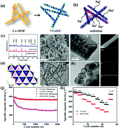 | ||
| Fig. 11 Brief illustration of (a) the synthesis process and (b) the sodium-storage process of 7-CoS/C. (c–i) Phase analysis: (c) XRD pattern of the as-prepared 7-CoS/C and 18.5-CoS/C; (d) Crystal structure of hexagonal CoS. Morphology characterization: (e) SEM, (f and g) TEM (inset: CoS particle size distribution diagram), (h) HRTEM and (i) EDS mapping (Co, S, C elements) of the as-prepared 7-CoS/C. (j) Cycling performance at 1 A g−1 and (k) rate capability of the 7-CoS/C and 18.5-CoS/C electrodes (7-CoS/C and 18.5-CoS/C represent the MOF-derived CoS/C calcinated at 600 and 800 °C, respectively). Reprinted from ref. 92, Copyright (2017), with permission from Elsevier. | ||
The sulfuration of MOFs can also be conducted under hydrothermal/solvothermal conditions followed by an annealing process to prepare metal sulfides. MOFs typically are dissolved under a hydrothermal process and act as a controlled-release resource of metal ions for the growth of metal sulfide.29,30 Two-dimensional holey Co4S3 (h-Co4S3) nanosheets were prepared via sulfuration of leaf-like cobalt-based MOFs in a solution of thioacetamide (TAA) with subsequent annealing, as shown in Fig. 12.29 Profiting from the nanosheet nature of the in-plane nanopores (10–30 nm), ultrathin depth (<30 nm), crumpled morphology, and micrometer-scale lateral size, the h-Co4S3 nanosheets delivered a high reversible capacity of 571 mA h g−1 at 0.1 A g−1, and long-life cycling stability, with a capacity retention of 80% after 400 cycles in SIBs in ether-based electrolyte. In the case of solvothermal synthesis, ethanol solvent is frequently used. MOFs can usually preserve their morphology in this solvothermal process.94,95 However, elevating the solvothermal temperature results in hollow structures.103,104 Through a simple solvothermal sulfuration of the ZIF-67 precursor and subsequent calcination, Co9S8@carbon yolk–shell nanocages (Co9S8@CYSNs) were successfully prepared, which are composed of Co9S8 nanoparticles dispersed in an amorphous carbon matrix inside a rigid carbon shell. Benefiting from this unique structure, the Co9S8@CYSNs exhibited a large capacity of 549 mA h g−1 at 0.1 A g−1, a superior rate capability (100 mA h g−1 at 10 A g−1) and excellent cycle stability with a low capacity decay of 0.019% per cycle over 800 cycles. Recently, Lou's group have combined solvothermal synthesis with complex-anion conversion and exchange processes to prepare cobalt sulfide multi-shelled nanoboxes derived from ZIF-67.27 The as-prepared cobalt sulfide showed enhanced sodium-storage performance, which retained a high capacity of 438 mA h g−1 after 100 cycles at 500 mA g−1.
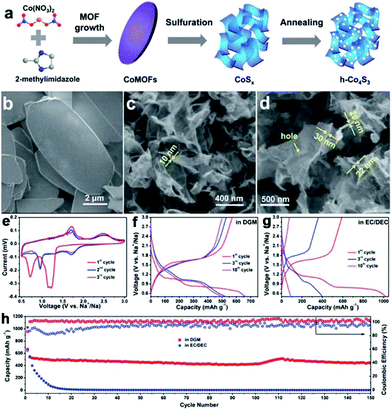 | ||
| Fig. 12 (a) Schematic of the fabrication of 2D h-Co4S3 nanosheets, including the growth and sulfuration of Co-MOFs, and annealing treatment of CoSx nanosheets. SEM images of (b) Co-MOFs, (c) CoSx and (d) h-Co4S3 nanosheets. (e) CV curves of the h-Co4S3 anode in ether-based electrolyte (1.0 M NaCF3SO3 in diglyme (DGM)). Discharge–charge profiles of the h-Co4S3 anode in (f) ether-based electrolyte and (g) carbonate-based electrolyte (1.0 M NaClO4 in EC/DEC with 5% FEC). (h) Cycling stability of h-Co4S3 electrodes in DGM-based electrolyte and in carbonate-based electrolyte, tested at 0.1 A g−1. Reproduced from ref. 29 with permission from the Royal Society of Chemistry. | ||
A two-step sulfuration method has also been developed to synthesize metal sulfides from MOFs. In a typical synthesis, MOFs are firstly pyrolyzed in an inert atmosphere to build ultrafine metal nanoparticles embedded in a porous carbon matrix structure, due to the uniformly distributed metal ions and organic ligands. Then, the structure is further subjected to sulfuration using either a thermal or hydrothermal/solvothermal method. The successive carbonization and sulfuration usually result in metal sulfide nanoparticles embedded in a porous carbon matrix structure, which favours outstanding electrochemical performance in SIBs.97,105 A CoS2-C/CNT nanocomposite (as shown in Fig. 13), with CoS2 nanoparticles embedded in porous carbonaceous micropolyhedra interlinked by CNTs, was synthesized from ZIF-67 using the two-step sulfuration strategy of Ma et al.93 Due to its appealing structure, the CoS2-C/CNT nanocomposite provided excellent energy storage performance in SIBs, delivering a capacity of 403 mA h g−1 after 200 cycles (capacity retention of 90%) at 100 mA g−1.
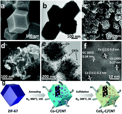 | ||
| Fig. 13 Morphological and structural features of the ZIF-67 precursor and the Co-C/CNT intermediate. SEM and HRTEM images of (a and b) ZIF-67 and (c–f) Co-C/CNT. The lattice fringes highlighted in (f) are in good agreement with the JCPDS reference card no. 15-0806 for metallic cobalt and the characteristic (002) interlayer spacing for graphitic carbon. (g) Schematic drawing of the formation process to obtain the CoS2-C/CNTs nanocomposite. Adapted with permission from ref. 93. Copyright (2018) American Chemical Society. | ||
To further enhance the electronic conductivity and buffer the stress caused by the volume change, carbon-based materials are introduced, in addition to the MOF-derived metal sulfides. Yin's group synthesized a ZnS-Sb2S3@C core–double-shell polyhedron structure through a sulfurization reaction between polymeric resorcinol–formaldehyde-coated ZIF-8 and TAA, followed by an ion exchange process between Zn2+ and Sb3+ and subsequent annealing, as displayed in Fig. 14.28 The authors found that an additional carbon shell not only acted as a protective layer to preserve the rigid construction of ZIF-8 and accommodate the volume changes during cycling, but also enhanced the electronic conductivity to improve the cycling stability and rate property. Benefiting from these structural and compositional features, the composites showed excellent sodium storage performance with a high reversible capacity of 630 mA h g−1 at 100 mA g−1 after 120 cycles. Polydopamine21,106,107 and hydrothermal glucose derivative30,108 have also been regarded as good coating layers for MOFs to construct an additional carbon shell in the final MOF-derived metal sulfides. Moreover, TiO2 coating is reported to improve the electrochemical performance of MOF-derived FeS.22 In addition, RGO has been well accepted as an effective substrate for the construction of carbon-based nanocomposites with MOF-derived metal sulfides.96,98,109 Through a one-step thermal transformation of three-dimensional graphene (3DG)-wrapped MOF composite, a core–shell FeS@carbon nanocomposite encapsulated within 3DG (3DG/FeS@C) was fabricated by Bu et al.96 Benefiting from the effective ion/charge transport and robust structural stability guaranteed by the highly interpenetrated porous conductive network of 3DG, the free-standing 3DG/FeS@C electrode delivered a high capacity of 632 mA h g−1 after 80 cycles at 100 mA g−1 with excellent cycling stability (capacity retention of 97.9% after 300 cycles at 1 A g−1).
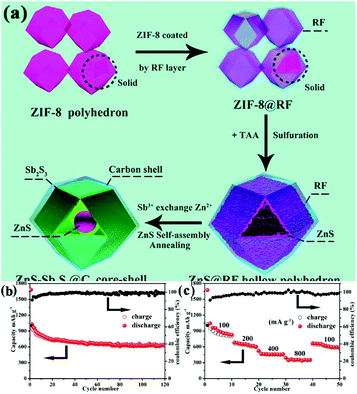 | ||
| Fig. 14 (a) Schematic illustration of the synthesis process. (b) Cycling performance (at 100 mA g−1) and (c) rate capability of the ZnS-Sb2S3@C core–shell SIB anodes. Adapted with permission from ref. 28. Copyright (2018) American Chemical Society. | ||
Due to their porous structure, with high SSA and good conductive features, MOF-derivative frameworks, such as MOF-derived carbon99,110,111 and metal compound/carbon composite,112,113 have been investigated as profitable templates for the growth of metal sulfides, forming desirable hierarchical structures. Lim et al. grew WS2 nanosheets onto a Prussian blue-derived nitrogen-doped carbon nanocubic framework (NCF) through a solvothermal method to prepare cubic-shaped WS2@NCF nanostructures with vertical rose petal-like layers.111 Because of good electrochemical transport properties resulting from the nanostructured hierarchical scaffolding and the highly conductive nature of the carbon framework, the as-prepared WS2@NCF exhibited a good cycling stability (0.1% capacity fading per cycle over 500 cycles) and high rate capacities of 384 and 151 mA h g−1 at 0.1 and 5 A g−1, respectively. SnS2 nanosheets coating on hollow cubic CoS2/C (CoS2/C@SnS2) composites with a hollow structure were fabricated using Co-MOFs as the starting material based on a two-step synthesis.113 The Co-MOFs were first converted to Co9S8via solvothermal sulfuration and subsequent annealing, which acted as a substrate for solvothermal coating of the SnS2 nanosheets. When used as anode materials for SIBs, the CoS2/C@SnS2 delivered excellent cycling stability and rate capability, which maintained a high specific capacity of 400 mA h g−1 after 3500 cycles at 10 A g−1.
5. Other materials
Intensive efforts have been made to extend the use of versatile MOFs to the structural design of many other materials, such as metal selenides,114,115 metal phosphides,25,26 metal carbides116,117 carbon nitride,118etc.5.1 Metal selenides
Recently, metal selenides, such as CoSe2, MoSe2 and ZnSe, have shown great potential as anode materials for SIBs because of their high theoretical capacity and excellent electrochemical performance.24,115 Metal selenides working on a conversion mechanism are reversibly converted to Na2Se in a way that is similar to that of metal oxides and metal sulfides. The metal (M)–Se bond is even weaker than the M–O and M–S bond and the discharge product (Na2Se) of metal selenides also exhibits a better conductivity than Na2O or Na2S.119 As a result, metal selenides usually deliver a higher kinetic reactivity, as well as better rate capability, than their oxide and sulfide counterparts. However, the significant volume change during cycling and the inadequate electrical conductivity of the selenides still hinder their application.120,121 As a consequence, great efforts have been devoted to designing rational nanostructures to solve these problems, and MOFs have played a remarkable role in this field. Several selenization methods, such as thermal, hydrothermal and two-step selenization, have been developed to prepare metal selenide nanostructures from MOFs.In a typical thermal selenization process, MOFs mixed with selenium powder are calcinated at elevated temperatures and transformed to metal selenides.23,24,122 Yolk–shell CoSe/C mesoporous dodecahedra were successfully prepared by Zhang et al. through annealing ZIF-67 with selenium powder in an Ar atmosphere.23 During the annealing process, CoSe nanoparticles were formed in situ via reaction between the cobalt species in ZIF-67 and the selenium powder, and the organic species were simultaneously pyrolyzed to nitrogen-doped carbon. In a revised thermal selenization method, annealing of the mixture of MOFs and selenium powder was conducted in a vacuum. In this case, the processes of carbonization, selenization and selenium vapour deposition took place simultaneously, resulting in the formation of selenium/selenide/carbon composites, as reported by Yang et al.114 They achieved a record high Se content of 76 wt% for Se-based materials and, thus, enhanced capacity and rate capability (490 and 384 mA h g−1 at 0.1 and 2.0 A g−1), as well as excellent cycle stability (no decay over 700 cycles at 2 A g−1), which is ascribed to the dominant capacitive behaviour and the robust MOF-derived structure.
The selenization of MOFs can also be carried out under hydrothermal conditions.119,123 Lou's group reported a two-step ion exchange method based on a hydrothermal process to synthesize selenides from Co–Co Prussian blue analogue microcubes and doped Cu ions, and, finally, hierarchical Cu-doped CoSe2 microboxes assembled by ultrathin nanosheets were fabricated.123 Due to their unique structural and compositional advantages, the Cu-doped CoSe2 microboxes demonstrated enhanced sodium storage properties, with a high reversible capacity (492 mA h g−1), good rate capability (185 mA h g−1 at 3 A g−1) and long-term cycle stability (94% capacity retention over 500 cycles). In an alternative approach, metal selenides were prepared from MOFs through a two-step selenization method, where MOFs were subjected to successive carbonization and selenization.124–126 Inherited from the structure of the carbonized MOFs, the as-obtained metal selenides usually show a structure consisting of metal selenide nanoparticles encapsulated in a porous carbon framework. Pan et al. fabricated a composite consisting of CoSe nanoparticles uniformly dispersed in porous carbon polyhedra (CoSe@PCP) using this two-step strategy, as shown in Fig. 15.115 When used as an anode material for SIBs, the CoSe@PCP delivered superior performance, with a high reversible capacity (341 mA h g−1 after 100 cycles at 0.1 A g−1), good rate capability (208 mA h g−1 at 4 A g−1) and excellent cycling stability (capacity fading of 0.2% per cycle over 500 cycles), benefiting from the synergistic effect of nanostructured CoSe and PCP.
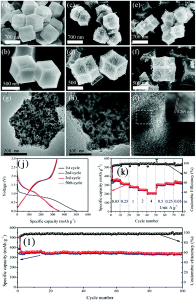 | ||
| Fig. 15 FESEM images of (a and b) ZIF-67, (c and d) Co@PCP and (e and f) CoSe@PCP at different magnifications. (g, h and i) HRTEM images of CoSe@PCP at different magnifications. (j) Galvanostatic charge and discharge profiles in the 1st, 2nd, 3rd and 50th cycles at 100 mA g−1. (k) Rate performance and (l) cycling performance at 100 mA g−1 of CoSe@PCP. Reprinted from ref. 115, Copyright (2017), with permission from Elsevier. | ||
5.2 Metal phosphides
Metal phosphides have drawn much attention as promising anode materials for SIBs due to their high theoretical specific capacity, low cost and relatively low intercalation potential.127,128 They store Na ions by producing NaPy during repeated charge–discharge cycles. However, the huge volume change during cycling, and inferior electronic conductivity, normally result in rapid capacity decay and sluggish kinetics for these materials. Several strategies, such as rational design of nanostructures and composites with carbon, have been reported to address the above issues. Among them, a MOF-derivative strategy should be the most simple and effective to prepare high-performance metal phosphides, such as CoP,129 FeP130 and Sn4P3.131 A nanocomposite consisting of CoP nanoparticles uniformly embedded in N-doped carbon nanosheets was fabricated via a simple one-step calcination of Co-based MOFs with red phosphorus.26 Because of the nanoscale CoP particle size, robust P–C bonding and highly conductive carbon nanosheets, the composite exhibited a high capacity (598 mA h g−1 at 0.1 A g−1), fast kinetics (174 mA h g−1 at 20 A g−1) and a long cycle life (98.5% capacity retention after 900 cycles at 1 A g−1). The same group further studied the sodium storage mechanisms and found that the composite structure showed an important impact on the charge mechanism. It was demonstrated that CoP underwent a conversion mechanism during the first discharge, to form Co metal nanoparticles and Na3P. If the CoP particles are small enough and well confined by the carbon matrix, the conversion reaction (Co + Na3P − 3e− → CoP + 3Na+) preferentially occurs during the first charge process. Otherwise, the de-alloying reaction (Na3P − 3e− → P + 3Na+) occurs during the first charge process. In work reported by Yang's group,25 a porous FeP/C nanostructure was synthesized through low-temperature phosphorization of Prussian blue analogues with the presence of sodium hypophosphite. Due to the highly porous nanocubic structure with FeP nanoparticles distributed in the carbon scaffold, the as-obtained FeP/C composite showed remarkable sodium storage performance in terms of high capacity (410 mA h g−1 at 100 mA g−1), excellent rate capability and long cycle life.6. Conclusions and perspectives
Exploring advanced electrode materials for SIBs is currently of great interest. Recently, MOFs have been extensively used as precursors or templates to design and fabricate colourful nanostructures. Materials prepared based on MOFs typically show nanoscaled particle size, well-developed porosity, as well as designable microstructure and morphology, which make them particularly attractive as promising electrode materials for SIBs. In this review, recent progress on MOF-based materials, including carbons, metal oxides, sulfides and others, as anode materials for SIBs is summarized. Through optimization of the precursor and the preparation process, such as calcination temperature, MOF-derived carbon materials with designed microstructure, porosity and morphology have been fabricated and showed outstanding electrochemical performance in terms of capacity, rate capability and cycling stability in SIBs, as a result of their desirable structures. Metal oxides derived from MOFs, including TiO2, cobalt-based oxides, binary metal oxides and many others, showed diverse nanostructures, such as a typical nanocomposite structure consisting of metal oxide nanoparticles embedded in a porous carbon matrix. These nanostructures are beneficial to effectively buffer the volume change and improve the charge transfer as well as the mass transportation. As a result, these MOF-derived metal oxides show enhanced sodium storage performance with good rate capability and cycling stability. Moreover, several strategies, including an additional carbon matrix, such as graphene, and defect chemistry, etc. have been employed to further improve the performance of MOF-derived metal oxides. In addition, metal sulfides, selenides and phosphides with versatile structures have also been prepared from MOFs using similar strategies, and they have delivered remarkable electrochemical performances when applied as anode materials in SIBs.Although tremendous progress on the development of MOF-based electrode materials for SIBs has been demonstrated, many challenges still remain and hinder the application of these materials in practice. First, large-scale production of MOF-derived materials needs to be further explored to ensure that high-quality products are achieved. Aimed at this, the transformation process from MOFs to various target materials needs to be further studied. Second, most of the as-obtained MOF-derived materials exhibit a low initial coulombic efficiency (typically less than 60%) because of a high SSA and defect surface, which is far from the practical standard of 85%. Efforts in surface chemistry or pre-sodiation techniques should be made to alleviate this mismatch. Third, the stacking density as well as the specific stacked volume capacity are very important in many applications and are normally related to the processability of the electrode materials. These features need to be carefully taken into account for these MOF-derived materials, because of their high porous nanostructure. Finally, to achieve a high working voltage for a full cell, a low insertion potential is preferred for the anode materials. Future developments in MOF-derived electrode materials should focus primarily on low potential insertion materials, such as carbon, TiO2 and metal phosphides, etc. Nevertheless, with sustained research efforts devoted to these fields, great opportunities exist to realize the practical applications of MOF-derived materials in SIBs.
Conflicts of interest
There are no conflicts to declare.Acknowledgements
Financial support from the National Nature Science Foundation of China (No. 51902301) and the Natural Science Foundation of Zhejiang Province (No. LY18E060005, LY18E020007, LY19E020006 and LQ18E030005) is gratefully acknowledged.References
- J. F. Li, L. Han, Y. Q. Li, J. L. Li, G. Zhu, X. J. Zhang, T. Lu and L. K. Pan, Chem. Eng. J., 2020, 380, 122590 CrossRef CAS.
- J. F. Li, L. Han, X. J. Zhang, G. Zhu, T. Q. Chen, T. Lu and L. K. Pan, Chem. Eng. J., 2019, 370, 800–809 CrossRef CAS.
- X. X. Li, S. S. Zheng, L. Jin, Y. Li, P. B. Geng, H. G. Xue, H. Pang and Q. Xu, Adv. Energy Mater., 2018, 8, 1800716 CrossRef.
- W. Qin, T. Q. Chen, L. K. Pan, L. Y. Niu, B. W. Hu, D. S. Li, J. L. Li and Z. Sun, Electrochim. Acta, 2015, 153, 55–61 CrossRef CAS.
- T. Q. Chen, Y. Liu, L. K. Pan, T. Lu, Y. F. Yao, Z. Sun, D. H. C. Chua and Q. Chen, J. Mater. Chem. A, 2014, 2, 4117–4121 RSC.
- G. Zou, H. Hou, P. Ge, Z. Huang, G. Zhao, D. Yin and X. Ji, Small, 2018, 14, 1702648 CrossRef PubMed.
- H. S. Hou, C. E. Banks, M. J. Jing, Y. Zhang and X. B. Ji, Adv. Mater., 2015, 27, 7861–7866 CrossRef CAS PubMed.
- L. Zhang, H. Liu, W. Shi and P. Cheng, Coord. Chem. Rev., 2019, 388, 293–309 CrossRef CAS.
- M. Zhong, L. J. Kong, N. Li, Y.-Y. Liu, J. Zhu and X.-H. Bu, Coord. Chem. Rev., 2019, 388, 172–201 CrossRef CAS.
- J. B. Li, D. Yan, S. J. Hou, T. Lu, Y. F. Yao, D. H. C. Chua and L. K. Pan, Chem. Eng. J., 2018, 335, 579–589 CrossRef CAS.
- J. B. Li, D. Yan, S. J. Hou, T. Lu, Y. F. Yao and L. K. Pan, Chem. Eng. J., 2018, 354, 172–181 CrossRef CAS.
- S. M. Cohen, Chem. Rev., 2012, 112, 970–1000 CrossRef CAS PubMed.
- Y. Xu, Q. Li, H. Xue and H. Pang, Coord. Chem. Rev., 2018, 376, 292–318 CrossRef CAS.
- W. Shi, X. Xu, L. Zhang, W. Liu and X. Cao, Funct. Mater. Lett., 2018, 11, 1830006 CrossRef CAS.
- J. K. Li, D. Wang, J. S. Zhou, L. Hou and F. M. Gao, ChemElectroChem, 2019, 6, 917–927 CrossRef CAS.
- Y. V. Kaneti, J. Zhang, Y. B. He, Z. J. Wang, S. Tanaka, M. S. A. Hossain, Z. Z. Pan, B. Xiang, Q. H. Yang and Y. Yamauchi, J. Mater. Chem. A, 2017, 5, 15356–15366 RSC.
- H.-H. Li, Z.-Y. Li, X.-L. Wu, L.-L. Zhang, C.-Y. Fan, H.-F. Wang, X.-Y. Li, K. Wang, H.-Z. Sun and J.-P. Zhang, J. Mater. Chem. A, 2016, 4, 8242–8248 RSC.
- X. J. Zhang, M. Wang, G. Zhu, D. S. Li, D. Yan, T. Lu and L. K. Pan, Ceram. Int., 2017, 43, 2398–2402 CrossRef CAS.
- S. T. Liu, J. S. Zhou and H. H. Song, Adv. Energy Mater., 2018, 8, 1800569 CrossRef.
- G. Zou, X. Jia, Z. Huang, S. Li, H. Liao, H. Hou, L. Huang and X. Ji, Electrochim. Acta, 2016, 196, 413–421 CrossRef CAS.
- J. W. Chen, S. H. Li, V. Kumar and P. S. Lee, Adv. Energy Mater., 2017, 7, 1700180 CrossRef.
- X. Xu, Z. Liu, S. Ji, Z. Wang, Z. Ni, Y. Lv, J. Liu and J. Liu, Chem. Eng. J., 2019, 359, 765–774 CrossRef CAS.
- Y. F. Zhang, A. Q. Pan, L. Ding, Z. L. Zhou, Y. P. Wang, S. Y. Niu, S. Q. Liang and G. Z. Cao, ACS Appl. Mater. Interfaces, 2017, 9, 3624–3633 CrossRef CAS PubMed.
- S. H. Yang, S.-K. Park and Y. C. Kang, Chem. Eng. J., 2019, 370, 1008–1018 CrossRef CAS.
- Y. Von Lim, S. Huang, Y. Zhang, D. Kong, Y. Wang, L. Guo, J. Zhang, Y. Shi, T. P. Chen, L. K. Ang and H. Y. Yang, Energy Storage Mater., 2018, 15, 98–107 CrossRef.
- K. Zhang, M. Park, J. Zhang, G.-H. Lee, J. Shin and Y.-M. Kang, Nano Res., 2017, 10, 4337–4350 CrossRef CAS.
- X. Wang, Y. Chen, Y. J. Fang, J. T. Zhang, S. Y. Gao and X. W. Lou, Angew. Chem., Int. Ed., 2019, 58, 2675–2679 CrossRef CAS.
- S. H. Dong, C. X. Li, X. L. Ge, Z. Q. Li, X. G. Miao and L. W. Yin, ACS Nano, 2017, 11, 6474–6482 CrossRef CAS.
- Y. Dong, W. Shi, P. Lu, J. Qin, S. Zheng, B. Zhang, X. Bao and Z.-S. Wu, J. Mater. Chem. A, 2018, 6, 14324–14329 RSC.
- Y. Cai, H. Yang, J. Zhou, Z. Luo, G. Fang, S. Liu, A. Pan and S. Liang, Chem. Eng. J., 2017, 327, 522–529 CrossRef CAS.
- M. A. Munozmarquez, D. Saurel, J. L. Gomezcamer, M. Casascabanas, E. Castillomartinez and T. Rojo, Adv. Energy Mater., 2017, 7, 1700463 CrossRef.
- X. J. Zhang, G. Zhu, M. Wang, J. B. Li, T. Lu and L. K. Pan, Carbon, 2017, 116, 686–694 CrossRef CAS.
- W. Luo, F. Shen, C. Bommier, H. Zhu, X. L. Ji and L. B. Hu, Acc. Chem. Res., 2016, 49, 231–240 CrossRef CAS PubMed.
- K. Y. Zou, P. Cai, C. Liu, J. Y. Li, X. Gao, L. Q. Xu, G. Q. Zou, H. S. Hou, Z. M. Liu and X. B. Ji, J. Mater. Chem. A, 2019, 7, 13540–13549 RSC.
- G. Q. Zou, H. S. Hou, C. W. Foster, C. E. Banks, T. X. Guo, Y. L. Jiang, Y. Zhang and X. B. Ji, Adv. Sci., 2018, 5, 1800241 CrossRef PubMed.
- D. A. Stevens and J. R. Dahn, J. Electrochem. Soc., 2000, 147, 1271–1273 CrossRef CAS.
- B. W. Xiao, T. Rojo and X. L. Li, ChemSusChem, 2018, 133–144 Search PubMed.
- J. Meng, X. Liu, J. Li, Q. Li, C. Zhao, L. Xu, X. Wang, F. Liu, W. Yang, X. Xu, Z. Liu, C. Niu and L. Mai, Nano Lett., 2017, 17, 7773–7781 CrossRef CAS PubMed.
- M. Du, D. Song, A. M. Huang, R. X. Chen, D. Q. Jin, K. Rui, C. Zhang, J. X. Zhu and W. Huang, Angew. Chem., Int. Ed., 2019, 58, 5307–5311 CrossRef CAS PubMed.
- X. Shi, Z. Zhang, Y. Fu and Y. Gan, Mater. Lett., 2015, 161, 332–335 CrossRef CAS.
- Q. Qu, J. Yun, Z. Wan, H. Zheng, T. Gao, M. Shen, J. Shao and H. Zheng, RSC Adv., 2014, 4, 64692–64697 RSC.
- N. Ingersoll, Z. Karimi, D. Patel, R. Underwood and R. Warren, Electrochim. Acta, 2019, 297, 129–136 CrossRef CAS.
- G. Q. Zou, H. S. Hou, X. Y. Cao, P. Ge, G. G. Zhao, D. L. Yin and X. B. Ji, J. Mater. Chem. A, 2017, 5, 23550–23558 RSC.
- X. Gao, G. Zhu, X. Zhang and T. Hu, Microporous Mesoporous Mater., 2019, 273, 156–162 CrossRef CAS.
- X. Gu, P. Dai, L. Li, J. Li, D. Li, H. Zhang and X. Zhao, ChemistrySelect, 2016, 1, 6442–6447 CrossRef CAS.
- Y. Liu, G. Wei, L. Pan, M. Xiong, H. Yan, Y. Li, C. Lu and Y. Qiao, ChemElectroChem, 2017, 4, 3244–3249 CrossRef CAS.
- X. D. Shi, Y. X. Chen, Y. Q. Lai, K. Zhang, J. Li and Z. Zhang, Carbon, 2017, 123, 250–258 CrossRef CAS.
- L. J. Kong, J. Zhu, W. Shuang and X.-H. Bu, Adv. Energy Mater., 2018, 8, 1801515 CrossRef.
- Y. Hu, Y. Chen, Y. Liu, W. Li, M. Zhu, P. Hu, H. Jin and Y. Li, Microporous Mesoporous Mater., 2018, 270, 67–74 CrossRef CAS.
- C. Chen, M. Wu, Z. Xu, T. Feng, J. Yang, Z. Chen, S. Wang and Y. Wang, J. Colloid Interface Sci., 2019, 538, 267–276 CrossRef CAS PubMed.
- W. H. Li, S. H. Hu, X. Y. Luo, Z. L. Li, X. Z. Sun, M. S. Li, F. F. Liu and Y. Yu, Adv. Mater., 2017, 29, 1605820 CrossRef PubMed.
- W. G. Wang, Y. Liu, X. Wu, J. Wang, L. J. Fu, Y. S. Zhu, Y. P. Wu and X. Liu, Adv. Mater. Technol., 2018, 3, 1800004 CrossRef.
- Y. Mei, Y. Huang and X. Hu, J. Mater. Chem. A, 2016, 4, 12001–12013 RSC.
- H. Xu, Y. Liu, T. Qiang, L. Qin, J. Chen, P. Zhang, Y. Zhang, W. Zhang, W. Tian and Z. Sun, Energy Storage Mater., 2019, 17, 126–135 CrossRef.
- H. He, Q. Zhang, H. Wang, H. Zhang, J. Li, Z. Peng, Y. Tang and M. Shao, J. Power Sources, 2017, 354, 179–188 CrossRef CAS.
- H. Li, Z. Zhang, X. Huang, T. Lan, M. Wei and T. Ma, J. Energy Chem., 2017, 26, 667–672 CrossRef.
- X. Shi, Z. Zhang, K. Du, Y. Lai, J. Fang and J. Li, J. Power Sources, 2016, 330, 1–6 CrossRef CAS.
- G. Zou, J. Chen, Y. Zhang, C. Wang, Z. Huang, S. Li, H. Liao, J. Wang and X. Ji, J. Power Sources, 2016, 325, 25–34 CrossRef CAS.
- X. Zhao, C. Yan, X. Gu, L. Li, P. Dai, D. Li and H. Zhang, ChemElectroChem, 2017, 4, 1516–1522 CrossRef CAS.
- J. F. Li, X. J. Zhang, L. Han, D. Yan, S. J. Hou, T. Lu, Y. F. Yao and L. K. Pan, J. Mater. Chem. A, 2018, 6, 24224–24231 RSC.
- Z. Zhang, Y. An, X. Xu, C. Dong, J. Feng, L. Ci and S. Xiong, Chem. Commun., 2016, 52, 12810–12812 RSC.
- T. Lin, C. Yang, Z. Wang, H. Yin, X. Lü, F. Huang, J. Lin, X. Xie and M. Jiang, Energy Environ. Sci., 2014, 7, 967–972 RSC.
- J. Chen, W. X. Song, H. S. Hou, Y. Zhang, M. J. Jing, X. N. Jia and X. B. Ji, Adv. Funct. Mater., 2015, 25, 6793–6801 CrossRef CAS.
- X. J. Wei, X. P. Wang, X. Tan, Q. Y. An and L. Q. Mai, Adv. Funct. Mater., 2018, 28, 1804458 CrossRef.
- H. Xu, G. Zhu and B. Hao, J. Mater. Sci. Technol., 2019, 35, 100–108 CrossRef.
- Y. Wu, J. Meng, Q. Li, C. Niu, X. Wang, W. Yang, W. Li and L. Mai, Nano Res., 2017, 10, 2364–2376 CrossRef CAS.
- Y. Pang, S. Chen, C. Xiao, S. Ma and S. Ding, J. Mater. Chem. A, 2019, 7, 4126–4133 RSC.
- Y. Han, J. Li, T. Zhang, P. Qi, S. Li, X. Gao, J. Zhou, X. Feng and B. Wang, Chem. – Eur. J., 2018, 24, 1651–1656 CrossRef CAS PubMed.
- G. Fang, J. Zhou, Y. Cai, S. Liu, X. Tan, A. Pan and S. Liang, J. Mater. Chem. A, 2017, 5, 13983–13993 RSC.
- H. Zhang, I. Hasa and S. Passerini, Adv. Energy Mater., 2018, 8, 1702582 CrossRef.
- X. J. Zhang, W. Qin, D. S. Li, D. Yan, B. W. Hu, Z. Sun and L. K. Pan, Chem. Commun., 2015, 51, 16413–16416 RSC.
- D. S. Li, D. Yan, X. J. Zhang, J. B. Li, T. Lu and L. K. Pan, J. Colloid Interface Sci., 2017, 497, 350–358 CrossRef CAS PubMed.
- L.-Y. Qi, Y.-W. Zhang, Z.-C. Zuo, Y.-L. Xin, C.-K. Yang, B. Wu, X.-X. Zhang and H.-H. Zhou, J. Mater. Chem. A, 2016, 4, 8822–8829 RSC.
- F. Zou, Y.-M. Chen, K. Liu, Z. Yu, W. F. Liang, S. M. Bhaway, M. Gao and Y. Zhu, ACS Nano, 2016, 10, 377–386 CrossRef CAS PubMed.
- X. J. Zhang, G. Zhu, D. Yan, T. Lu and L. K. Pan, J. Alloys Compd., 2017, 710, 575–580 CrossRef CAS.
- Y. S. Cai, G. Z. Fang, J. Zhou, S. N. Liu, Z. G. Luo, A. Q. Pan, G. Z. Cao and S. Q. Liang, Nano Res., 2018, 11, 449–463 CrossRef CAS.
- L. Kong, C.-C. Xie, H. Gu, C.-P. Wang, X. Zhou, J. Liu, Z. Zhou, Z.-Y. Li, J. Zhu and X.-H. Bu, Small, 2018, 14, 1800639 CrossRef PubMed.
- X. Lu, F. Luo, Q. Xiong, H. Chi, H. Qin, Z. Ji, L. Tong and H. Pan, Mater. Res. Bull., 2018, 99, 45–51 CrossRef CAS.
- Y. Wang, Q. Deng, W. Xue, Z. Jian, R. Zhao and J. Wang, J. Mater. Sci., 2018, 53, 6785–6795 CrossRef CAS.
- L. F. Shen, Q. Che, H. S. Li and X. G. Zhang, Adv. Funct. Mater., 2014, 24, 2630–2637 CrossRef CAS.
- B. Li, J. Feng, Y. Qian and S. Xiong, J. Mater. Chem. A, 2015, 3, 10336–10344 RSC.
- J. Chen, Q. Ru, Y. Mo, S. Hu and X. Hou, Phys. Chem. Chem. Phys., 2016, 18, 18949–18957 RSC.
- W. Zhang, P. Cao, Z. Zhang, Y. Zhao, Y. Zhang, L. Li, K. Yang, X. Li and L. Gu, Chem. Eng. J., 2019, 364, 123–131 CrossRef CAS.
- G. Zou, H. Hou, G. Zhao, P. Ge, D. Yin and X. Ji, J. Mater. Chem. A, 2018, 6, 4839–4847 RSC.
- Y. Guo, Y. Y. Zhu, C. Yuan and C. Y. Wang, Mater. Lett., 2017, 199, 101–104 CrossRef CAS.
- X. J. Zhang, D. S. Li, G. Zhu, T. Lu and L. K. Pan, J. Colloid Interface Sci., 2017, 499, 145–150 CrossRef CAS PubMed.
- L. T. Yu, J. Liu, X. J. Xu, L. G. Zhang, R. Z. Hu, J. W. Liu, L. Z. Ouyang, L. C. Yang and M. Zhu, ACS Nano, 2017, 11, 5120–5129 CrossRef CAS.
- Q. Zhou, L. Liu, Z. Huang, L. Yi, X. Wang and G. Cao, J. Mater. Chem. A, 2016, 4, 5505–5516 RSC.
- P. Ge, C. Zhang, H. Hou, B. Wu, L. Zhou, S. Li, T. Wu, J. Hu, L. Mai and X. Ji, Nano Energy, 2018, 48, 617–629 CrossRef CAS.
- J. B. Li, J. L. Li, Z. B. Ding, X. L. Zhang, Y. Q. Li, T. Lu, Y. F. Yao, W. J. Mai and L. K. Pan, Chem. Eng. J., 2019, 378, 122108 CrossRef CAS.
- J. L. Li, W. Qin, J. P. Xie, R. Lin, Z. L. Wang, L. K. Pan and W. J. Mai, Chem. Eng. J., 2018, 332, 260–266 CrossRef CAS.
- L. Zhou, K. Zhang, J. Sheng, Q. An, Z. Tao, Y.-M. Kang, J. Chen and L. Mai, Nano Energy, 2017, 35, 281–289 CrossRef CAS.
- Y. Ma, Y. J. Ma, D. Bresser, Y. C. Ji, D. Geiger, U. Kaiser, C. Streb, A. Varzi and S. Passerini, ACS Nano, 2018, 12, 7220–7231 CrossRef CAS PubMed.
- Y. Zhao, Q. Fu, D. Wang, Q. Pang, Y. Gao, A. Missiul, R. Nemausat, A. Sarapulova, H. Ehrenberg, Y. Wei and G. Chen, Energy Storage Mater., 2019, 18, 51–58 CrossRef.
- A. Jin, M.-J. Kim, K.-S. Lee, S.-H. Yu and Y.-E. Sung, Nano Res., 2019, 12, 695–700 CrossRef CAS.
- F. Bu, P. Xiao, J. Chen, M. F. Aly Aboud, I. Shakir and Y. Xu, J. Mater. Chem. A, 2018, 6, 6414–6421 RSC.
- J. B. Li, D. Yan, X. J. Zhang, S. J. Hou, T. Lu, Y. F. Yao and L. K. Pan, J. Mater. Chem. A, 2017, 5, 20428–20438 RSC.
- R. Zhang, J. Xu, M. Jia, E. Pan, C. Zhou and M. Jia, J. Alloys Compd., 2019, 781, 450–459 CrossRef CAS.
- W. N. Ren, H. F. Zhang, C. Guan and C. W. Cheng, Adv. Funct. Mater., 2017, 27, 1702116 CrossRef.
- X. Gao, X. Zhang, J. Jiang and J. Chen, Mater. Lett., 2018, 228, 42–45 CrossRef CAS.
- K. J. Zhu, G. Liu, Y. J. Wang, J. Liu, S. T. Li, L. Y. Yang, S. L. Liu, H. Wang and T. Xie, Mater. Lett., 2017, 197, 180–183 CrossRef CAS.
- D. Cao, W. Kang, S. Wang, Y. Wang, K. Sun, L. Yang, X. Zhou, D. Sun and Y. Cao, J. Mater. Chem. A, 2019, 7, 8268–8276 RSC.
- S. H. Yang, S.-K. Park, J. K. Kim and Y. C. Kang, J. Mater. Chem. A, 2019, 7, 13751–13761 RSC.
- Y. Li, R. P. Zhang, W. Zhou, X. Wu, H. B. Zhang and J. Zhang, ACS Nano, 2019, 13, 5533–5540 CrossRef CAS PubMed.
- X. Liu, F. Zou, K. Liu, Z. Qiang, C. J. Taubert, P. Ustriyana, B. D. Vogt and Y. Zhu, J. Mater. Chem. A, 2017, 5, 11781–11787 RSC.
- H. Shangguan, W. Huang, C. Engelbrekt, X. Zheng, F. Shen, X. Xiao, L. Ci, P. Si and J. Zhang, Energy Storage Mater., 2019, 18, 114–124 CrossRef.
- Y. Yao, J. Zheng, Z. Gong, Z. Ding, J. Zhang, W. Yu, D. a. M. Bengono, H. Li, B. Zhang and H. Tong, J. Alloys Compd., 2019, 790, 288–295 CrossRef CAS.
- C. Kang, Y. Lee, I. Kim, S. Hyun, T. H. Lee, S. Yun, W. S. Yoon, Y. Moon, J. Lee, S. Kim and H. J. Lee, Materials, 2019, 12, 14 Search PubMed.
- J. Huang, X. Tang, Z. Li and K. Liu, J. Colloid Interface Sci., 2018, 532, 407–415 CrossRef CAS PubMed.
- Y. Von Lim, S. Huang, Q. Wu, Y. Zhang, D. Kong, Y. Wang, T. Xu, Y. Shi, Q. Ge, L. K. Ang and H. Y. Yang, Nano Energy, 2019, 61, 626–636 CrossRef CAS.
- Y. V. Lim, Y. Wang, D. Kong, L. Guo, J. I. Wong, L. K. Ang and H. Y. Yang, J. Mater. Chem. A, 2017, 5, 10406–10415 RSC.
- Y. Wang, W. Kang, D. Cao, M. Zhang, Z. Kang, Z. Xiao, R. Wang and D. Sun, J. Mater. Chem. A, 2018, 6, 4776–4782 RSC.
- L. Shi, D. Li, P. Yao, J. Yu, C. Li, B. Yang, C. Zhu and J. Xu, Small, 2018, 14, 1802716 CrossRef PubMed.
- X. Yang, S. Wang, D. Y. W. Yu and A. L. Rogach, Nano Energy, 2019, 58, 392–398 CrossRef CAS.
- J. B. Li, D. Yan, T. Lu, Y. F. Yao and L. K. Pan, Chem. Eng. J., 2017, 325, 14–24 CrossRef CAS.
- T. Chen, B. R. Cheng, R. P. Chen, Y. Hu, H. L. Lv, G. Y. Zhu, Y. R. Wang, L. B. Ma, J. Liang, Z. X. Tie, Z. Jin and J. Liu, ACS Appl. Mater. Interfaces, 2016, 8, 26834–26841 CrossRef CAS PubMed.
- J. Qiu, Z. Yang, Q. Li, Y. Li, X. Wu, C. Qi and Q. Qiao, J. Mater. Chem. A, 2016, 4, 13296–13306 RSC.
- J.-M. Fan, J.-J. Chen, Q. Zhang, B.-B. Chen, J. Zang, M.-S. Zheng and Q.-F. Dong, ChemSusChem, 2015, 8, 1856–1861 CrossRef CAS PubMed.
- G. Z. Fang, Q. C. Wang, J. Zhou, Y. P. Lei, Z. X. Chen, Z. Q. Wang, A. Q. Pan and S. Q. Liang, ACS Nano, 2019, 13, 5635–5645 CrossRef CAS PubMed.
- F. Zhang, C. Xia, J. J. Zhu, B. Ahmed, H. F. Liang, D. B. Velusamy, U. Schwingenschlögl and H. N. Alshareef, Adv. Energy Mater., 2016, 6, 1601188 CrossRef.
- J. H. Choi, S.-K. Park and Y. C. Kang, Small, 2019, 15, 1803043 CrossRef PubMed.
- L. Zeng, Y. Fang, L. Xu, C. Zheng, M.-Q. Yang, J. He, H. Xue, Q. Qian, M. Wei and Q. Chen, Nanoscale, 2019, 11, 6766–6775 RSC.
- Y. J. Fang, X.-Y. Yu and X. W. Lou, Adv. Mater., 2018, 30, 1706668 CrossRef PubMed.
- J. Yang, H. C. Gao, S. Men, Z. Q. Shi, Z. Lin, X. W. Kang and S. W. Chen, Adv. Sci., 2018, 5, 1800763 CrossRef PubMed.
- X. J. Xu, J. Liu, J. W. Liu, L. Z. Ouyang, R. Z. Hu, H. Wang, L. C. Yang and M. Zhu, Adv. Funct. Mater., 2018, 28, 1707573 CrossRef.
- X. Liu, Y. Liu, M. Feng and L.-Z. Fan, J. Mater. Chem. A, 2018, 6, 23621–23627 RSC.
- R. Jin, X. F. Li, Y. Sun, H. Shan, L. L. Fan, D. J. Li and X. L. Sun, ACS Appl. Mater. Interfaces, 2018, 10, 14641–14648 CrossRef CAS PubMed.
- Z. Li, L. Zhang, X. Ge, C. Li, S. Dong, C. Wang and L. Yin, Nano Energy, 2017, 32, 494–502 CrossRef CAS.
- X. Ge, Z. Li and L. Yin, Nano Energy, 2017, 32, 117–124 CrossRef CAS.
- X. Xu, J. Feng, J. Liu, F. Lv, R. Hu, F. Fang, L. Yang, L. Ouyang and M. Zhu, Electrochim. Acta, 2019, 312, 224–233 CrossRef CAS.
- E. Pan, Y. Jin, C. Zhao, Q. Chang and M. Jia, Ionics, 2018, 24, 3281–3285 CrossRef CAS.
| This journal is © the Partner Organisations 2020 |


