 Open Access Article
Single-unit-cell-thick layered electrocatalysts: from synthesis to application
Sanshuang
Gao
a,
Yifan
Liu
 b,
Hongyi
Li
*c,
Xijun
Liu
 a and
Jun
Luo
 *a
*a
aCenter for Electron Microscopy and Tianjin Key Lab of Advanced Functional Porous Materials, Institute for New Energy Materials & Low-Carbon Technologies, School of Materials Science and Engineering, Tianjin University of Technology, Tianjin 300384, China. E-mail: jluo@tjut.edu.cn
bCollege of Physics and Optoelectronic Engineering, Shenzhen University, Shenzhen 518060, China
cQualification of Products Supervision & Inspection Institute of Technology, Xinjiang Uygurs Autonomous Region, Urumqi 830011, China. E-mail: 422340661@qq.com
First published on 9th June 2020
Abstract
Electrocatalysts are critical for water splitting, carbon dioxide reduction, and zinc–air battery. However, the low-exposed surface areas of bulk electrocatalysts usually limit the complete utilization of active sites. Ultrathin electrocatalysts have noteworthy advantages in maximizing the use of active sites. Among the pioneering works on such performing catalysts, the development of single-unit-cell-thick layered electrocatalysts (STLEs) has attracted extensive attention owing to their superior specific surface area and large number of vacancies, which can provide abundant available surface active sites. Therefore, this minireview provides recent advances in STLE synthesis and applications, which are helpful for electrocatalysis-oriented researchers. Finally, the future perspectives and challenges for developing high-performance STLEs are proposed.
 Yifan Liu | Yifan Liu received his PhD degree from Heidelberg University, Germany, in 2019. His current scientific interests focus on nanomaterials, optics, and light–matter interaction. |
1. Introduction
During the last decade, the aggravation of energy crisis and global warming was witnessed. Therefore, developing eco-friendly strategies to produce clean and renewable energy sources is accelerated.1–3 Among various innovative options, photo- and electrocatalytic technologies have been regarded as efficient strategies for developing appropriate alternative energy sources to replace fossil fuels.4,5 Of them, the materials used for electrochemical water splitting, carbon dioxide reduction reaction (CO2RR), and rechargeable zinc–air batteries (ZABs) exhibit excellent catalytic activity, stability, selectivity, and faradaic efficiency (FE), allowing these reactions to be employed as promoters of clean-renewable energy sources.6–8 For instance, water splitting contains two half-reactions, i.e., hydrogen evolution reaction (HER), occurring on the cathode, and oxygen evolution reaction (OER), taking place on the anode.9 Hydrogen fuel, obtained by HER, has an extremely high mass-based energy density and environmental-friendly characteristics.10–12 OER is essential not only for water splitting but also for the charging process occurring in ZABs, one of the next-generation energy storage batteries.13,14 Low-carbon number hydrocarbons obtained by CO2RR are feedstocks and renewable fuels with a high potential in solving both energy crisis and global warming.15 The core of these processes is the electrocatalyst, which should have a large number of highly dispersed active sites.16 However, the agglomeration is a common phenomenon encountered in the development of such catalysts. Hence, a part of the active sites do not participate in the reactions, and thus the catalyst does not work at full capacity.17,18 Therefore, exploring appropriate methods for the synthesis of electrocatalysts without aggregates is significant to properly address the energy and environmental crisis.19Ultrathin nanomaterials (UNMs), benefiting from their unique properties such as thin thickness, large specific surface area, abundant active sites, excellent electroconductibility, and preferential diffusion paths, were developed in the attempts to overcome the agglomeration issues and to provide materials abundant of accessible active sites.20 For instance, Liu et al. prepared an ultrathin chiffon-like structure to overcome the agglomeration of layered double hydroxides, and Geenen et al. developed ultrathin NiSi2 films to avoid morphological agglomeration.21,22 Thus, UNMs are widely applied in electrocatalysis, photocatalysis, biosensors, biomedicine, energy storage, and energy conversion.23–25 For example, Zhang et al. prepared ultrathin Co3O4 and Co(OH)2 nanosheet arrays, and Dinh et al. reported ultrathin porous NiFeV for efficient electrocatalytic water splitting.26,27 Li et al. proposed ultrathin CeO2 nanoflakes loaded on graphene for ZABs, and Esrafilzadeh et al. reported atomically thin CeO2 for CO2RR.28,29
Although extensive works on UNM for electrocatalysis have been done, the preparations methods and potential applications still need to be upgraded.30 Many reviews mainly focusing on the synthesis (e.g., top-down and bottom-up approaches, including liquid exfoliation, thermal exfoliation, chemical vapor deposition, and wet-chemical synthesis31–34) and applications (e.g., photocatalysts,35 electrocatalysts,36–38 biomedicine, and biosensing39,40) of ultrathin layered nanomaterials have been published.31–41 Nevertheless, there are quite few reviews discussing the single-unit-cell-thick layered electrocatalysts (STLEs, thickness normally less than 1.0 nm), which essentially approaches the fundamental limit thickness of UNMs.42 That is, the STLE thickness is the fundamental lower limit of the UNM thickness,42 and the name of UNMs is used to represent single-/few-/multiple-unit-cell-thick nanomaterials in general.43 It should also be noted that the thickness of unit-cell-thick sheet (UCS) is equivalent to the STLE thickness.44,45 Generally, monolayer means single layer, which is also single-unit-cell-thick but from the view of layered structures.46–48 The concept of single-unit-cell-thick is from the view of crystal structures and more general.44 Unlike conventional UNMs, STLEs provide a thinner monolayer for exposing more surface-active sites and a larger number of structural defects, which changes the intrinsic activity. Specifically, single-unit-cell-thick layered double hydroxides (LDHs) with defect-rich surface-active sites exhibited excellent electric conductivity and spin-polarization characteristics, which were improved by the single-unit-cell thickness, in OER.49 Co3O4-based STLEs with distinct oxygen vacancies on the surface were prepared to understand the relationship between vacancies and catalytic activity in CO2RR.50 Single-unit-cell-thick CoSe2 in which 66.7% Co2+ acted as surface-active sites were prepared for OER performance.51 Therefore, all these outcomes highlight the significance of the morphostructural properties, particularly the thickness and vacancies of STLEs for catalytic performance. However, the preparation of such solids is challenging and several strategies were proposed.
In this minireview, we thoroughly summarize the latest progress in the synthesis of STLEs for electrocatalytic water splitting, CO2RR, and ZABs. Synthetic strategies (i.e., thermal and liquid exfoliation techniques) are in-depth discussed. The characterization results are also discussed. Subsequently, the electrocatalytic performance (i.e., catalytic activity, durability, selectivity, and FE) of STLEs is described aiming to highlight the recent advances in electrocatalysis. Therefore, this minireview aims to provide ideas for the design and synthesis of STLEs and discuss the challenges and perspectives for future applications.
2. Synthesis of STLEs
The structural properties, e.g., vacancies and thickness, have been considered as major factors affecting the quantity of active sites and electric conductivity of STLEs.23,52 Usually, electrocatalysts display a low number of active sites on the surfaces with low coordination numbers due to the stronger electrostatic interactions between layers which is detrimental for the catalytic activity. Therefore, pioneering works have devoted efforts to overcoming the electrostatic interactions between layers aiming to control the structural defects and the electronic properties of STLEs.53 In the following, the published synthetic strategies, i.e., thermal and liquid exfoliation, are detailed.2.1 Thermal exfoliation synthesis
Solvothermal/hydrothermal exfoliation techniques are widely used in preparing single-unit-cell-thick layered photocatalysts. Normally, the synthesis is performed in a stainless steel autoclave, at high temperature and autogeneous pressure.54–57 For instance, Huang et al. synthesized single-unit-cell-thick Bi2WO6 monolayers with surface tungsten vacancies by hydrothermal method;58 Di et al. employed solvothermal method to synthesize ultrathin BiOBr nanosheets, which was further used as template to obtain single-unit-cell-thick Bi2WO6.59 However, there is still little literature, focusing on the solvothermal/hydrothermal fabrication of STLEs, correlate to electrocatalytic applications. Thus, this section has cited three representative thermally exfoliation strategies, which successfully synthesize STLEs via solvothermal/hydrothermal intermediates.As illustrated in Fig. 1a. Gao et al. transferred cetyltrimethyl ammonium bromide (CTAB) and Co(acac)3 into a Teflon-lined autoclave with a mixture of ethylene glycol and distilled water (reacting under 180 °C for 20 h). Then, the self-assembled intermediates were thermally exfoliated (320 °C for 5 min) under air and O2 gaseous environment, respectively.50 The as-obtained thickness of VO-rich and VO-poor Co3O4 correspond to 0.84 nm (Fig. 1b and c), which fairly agrees with Co3O4 single-unit-cell. Similarly, as shown in Fig. 1d and e. Liang et al. blended Co2+ and Se into a mixture of diethylenetriamine and distilled water, maintained at 180 °C for 30 h. Subsequently, the assembled intermediates were thermally exfoliated (350 °C for 1 h) under atmosphere conditions for generating single-unit-cell-thick CoSe2, which presents 0.66 nm height.51 Besides, our group has dissolved Zn2+, Co2+, NH4F, and urea into distilled water, both of the mixed solution and rinsed Ti substrate were then transferred into Teflon-lined autoclave, which was maintained at 100 °C for 10 h. Subsequently, the hydrothermal growth of Zn-doped α-Co(OH)2 was placed in 1 M NaOH and 1 M NaBH4 solution at 5 °C for 2 h, and calcined at 250 °C for 3 h under an Ar atmosphere (Fig. 1f).44 In the light of discussing results, it can be stated that thermal methods have a great potential to prepare efficient STLEs for electrocatalytic reactions.
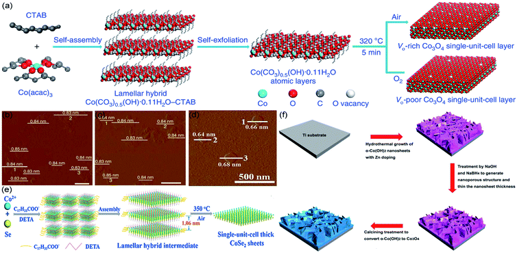 | ||
| Fig. 1 For thermal exfoliation. (a) Scheme for preparing single-unit-cell-thick layered Co3O4; AFM images of (b) VO-rich and (c) VO-poor single-unit-cell-thick layered Co3O4, respectively. Reproduced from ref. 50. Copyright 2017, Springer Nature. (d) AFM image and (e) scheme for fabricating single-unit-cell-thick layered CoSe2, respectively. Reproduced from ref. 51. Copyright 2015, Wiley-VCH. (f) Scheme for generating Zn-doped Co3O4 single-unit-cell. Reproduced from ref. 44. Copyright 2018, Elsevier. | ||
It is shown that these strategies of synthesis are very convenient to obtain STLEs due to the facile tuning of structural defects and morphology of STLEs by changing the temperature and gaseous environment during thermal treatment. Whereas, the automatic reaction leads to difficultly analyze the mechanistic principles of thermal process. Furthermore, thermal exfoliation requires complicated multi-step procedures (i.e., solvothermal/hydrothermal process and calcined treatment), which possibly cause potential safety risks, especially for the high-temperature solvothermal process.
2.2 Liquid exfoliation synthesis
Liquid exfoliation is a simple method to prepare monolayers by which the van der Waals interactions between layers is controlled. Typically, the multilayer solid precursor is immersed into a liquid, and ultrasounds are applied to overcome the attractive forces between layers and separate them. For instance, Miao et al. adopted a liquid exfoliation strategy to synthesize misfit-layered-structured Bi2Sr2Co2O8+δ (BSCO) nanosheets, which possess a single-unit-cell-thick structure (Fig. 2a and b).5 The bulk BSCO (misfit-layered CoO2 and SrO–BiO–BiO–SrO) involves weak van der Waals forces between BiO layers, which can be overcome to exfoliate the BSCO structure and obtain stable independent monolayers. Basically, the BSCO crystals were immersed in N-methyl-2-pyrrolidone and an ultrasonic treatment was applied in ice water for 24 h to obtain single-unit-cell-thick BSCO nanosheets. As seen in Fig. 2b, displaying atomic force microscopy (AFM) image and corresponding height results, the one-unit-cell BSCO has an average thickness of 3 nm, corresponding to the thickness of BSCO single unit cell.60 Moreover, Yang et al. proposed a self-surface charge exfoliation utilizing ultrasound treatment to fabricate single-unit-cell-thick ZnIn2S4 from multilayered ZnIn2S4.61 As illustrated in Fig. 2c, InCl3 and Zn(OOCCH3)2 were transferred into distilled water with refluxing and then sonicated continuously for 30 min to obtain the single-unit-cell-thick ZnIn2S4. During the synthetic process, a high amount of S2− was adsorbed onto the surface of bulk ZnIn2S4, causing a strong negative charge on the surface. As a result, the interactions between layers were weakened and the Coulombic repulsion promoted their separation.62 Each layer has a thickness of ∼2.5 nm, corresponding to the thickness of a unit cell in the (001) direction of ZnIn2S4 (Fig. 2d).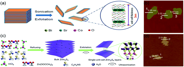 | ||
| Fig. 2 Schematic illustration of ultrasonic exfoliation of bulk (a) BSCO and (c) ZnIn2S4; AFM images of single-unit-cell (b) BSCO and (d) ZnIn2S4. (a and b) Reproduced from ref. 5. Copyright 2018, American Chemical Society. (c and d) Reproduced from ref. 61. Copyright 2017, Springer Nature. | ||
Liquid exfoliation can be achieved by different strategies, such as shear force, ultrasonication, or thermal energy, to exfoliate multilayered crystals and avoid other heteroatoms polluting catalyst.63,64 However, there are still some shortcomings, restricting the commercial applications of liquid exfoliation methods, such as continuous noise during ultrasonication and strongly ultrasonic energy destroying fragile layers.
3. Application of STLEs
With a graphene-like geometric structure, STLEs expose far more surface-active sites and low-coordinated surfaces compared to bulk catalysts, which endow them with plentiful dangling bonds for enhancing catalytic performance. Furthermore, benefitting from their unique morphostructural properties and strong synergistic effect with substrates, STLEs are expected to exhibit improved electric conductivity and spin-polarization characteristics as effective electrocatalysts in electrochemical energy storage and conversion. Therefore, the pioneering electrochemical applications, i.e., water splitting (including HER and OER), CO2RR, and ZABs, are favored and highlighted in the following discussions.3.1 STLEs for HER
The hydrogen, due to its zero-carbon emission, is regarded as a clean and renewable energy source to replace fossil fuels.65 In the last decade, platinum-based catalysts have been considered as state-of-the-art catalysts for industrial hydrogen production.66 Nevertheless, the high cost impedes their large-scale applications.67 Therefore, developing low-cost catalysts to replace platinum-based ones has become a hot topic in HER-oriented research. Recently, high-purity hydrogen was obtained by water splitting over transition metal dichalcogenides as HER catalysts.68 The monolayer molybdenum disulfide (M-MoS2, which is also single-unit-cell-thick MoS2) catalysts, benefiting from the high density of edges hosting the active sites, have been used in HER with high improved catalytic efficiency.69,70For instance, Su et al. have employed ultrathin alumina mask-assisted nanopore patterning to synthesize high-density porous MoS2 (HDP-MoS2).47 This unit-cell-thick HDP-MoS2 is richer in edges, as compared with the pristine monolayer MoS2 (M-MoS2). As Fig. 3a illustrated, large-area M-MoS2 (before ion beam etching) displays a triangular flake-like morphology with a thickness of ∼0.7 nm. Revealing M-MoS2 maintains structural integrity during the transfer process. Then, the ion beam etching was applied to generate high-density nanopores with an average diameter of 50 nm in uncovered MoS2. It should be noted that the transfer of HDP-MoS2 from the SiO2 substrate used for its preparation to the glassy carbon electrode (GCE) for HER was accomplished by spincoating polystyrene, HF etch, water cleaning and floating, and polystyrene pyrolysis. This process enhanced the adhesion between HDP-MoS2 and GCE, leading to a stable HER current density within 10![[thin space (1/6-em)]](https://www.rsc.org/images/entities/char_2009.gif) 000 s. Further, the pores in a monolayer structure increase the edge atom ratio, which promotes a high HER potential of −385 mV for HDP-MoS vs. reversible hydrogen electrode (RHE) at 10 mA cm−2 (Fig. 3c). Due to the excellent performance obtained for HER, the controllable edge engineering method can be extended to other materials.
000 s. Further, the pores in a monolayer structure increase the edge atom ratio, which promotes a high HER potential of −385 mV for HDP-MoS vs. reversible hydrogen electrode (RHE) at 10 mA cm−2 (Fig. 3c). Due to the excellent performance obtained for HER, the controllable edge engineering method can be extended to other materials.
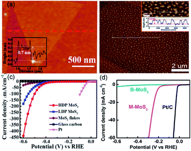 | ||
| Fig. 3 AFM images and the corresponding heights of (a) HDP-MoS2 precursor and (b) M-MoS2. The polarization curves of (c) HDP-MoS2 and (d) M-MoS2 in comparison with other catalysts. (a and c) Reproduced from ref. 47. Copyright 2018, American Chemical Society. (b and d) Reproduced from ref. 71. Copyright 2019, Elsevier. | ||
Wang et al. utilized the interlayer spaces of Mg–Al LDH to grow the two-dimensional (2D) M-MoS2, which suspended in water with the large-scale monolayer ratio (approximate 95%).71 As shown in Fig. 3b, the thickness and lateral size of M-MoS2 are ∼1 and 89 nm, respectively, based on the measurement of 400 unit-cell-thick particles. Overpotential and durability are critical indicators used to assess the performance of a catalyst for HER. The as-obtained HER activity of M-MoS2 exhibited a lower onset overpotential of 85 mV and an overpotential of 210 mv (vs. RHE) at 10 mA cm−2, which are significantly lower than bulk MoS2 (see Fig. 3d). This should be because compared with bulk MoS2, M-MoS2 owns larger ratios of edge atoms, which can expose massive active sites and facilitate electronic conduction. These are beneficial for catalyzing HER and thereby can lead to a better HER performance. The polarization curves, showing stability without any obvious change, were obtained before and after 1000 cyclic voltammetry cycles. All these results reveal that M-MoS2 has indeed a real potential to increase the efficiency of HER process.
3.2 STLEs for OER
The theoretical electrode potential of O2 generation is 1.23 V (vs. RHE), which indicates that considerable potentials (above theoretical potential) have to be applied on the electrode to promote OER.72 However, a high overpotential is energy-consuming, which makes the OER process unsustainable. At present, a hot research topic is the optimization of electrocatalysts to enhance the performance in OER. Fortunately, single-unit-cell-thick electrocatalysts proved to be appropriate materials to solve this challenge. The synthesized electrocatalysts could decrease the overpotential and thus make an economically feasible OER.Gao et al. employed the co-precipitation method to synthesize 2D single-unit-cell-thick LDH nanosheets (including CoNi-, NiFe-, CoFe-, and ZnCo-LDH NSs).46 According to the AFM image, the LDH nanosheets with hexagonal-like morphology, lateral sizes of ∼40 nm, and an average thickness of ∼1.3 nm are monodispersed (Fig. 4a and b). The thickness value between single- and two-layer LDH NSs (synthesized through liquid exfoliation method) probably be enhanced by the residual anions and/or solvents. Density functional theory (DFT) calculations reveal that CoFe- and NiFe-LDHs accelerate electronic spin-polarization, reduce energy gaps, and hence enhance electron mobility.46 Furthermore, the single-unit-cell-thick thickness exhibits vast surface defects, which can serve as catalytically active sites. To investigate OER performance, polarization curves were tested, in which the loading technique of the bulk and LDH NSs catalysts was dropping and evaporating the homogeneous catalyst inks onto fresh GCE. As shown in Fig. 4c, as compared with bulk LDH (green line), bimetallic LDH NSs (orange line) exhibit superior overpotential and Tafel slopes. Among these bimetallic LDH NSs, CoFe-LDH NSs revealed the lowest overpotential (280 mV at 10 mA cm−2) and excellent TOF values (5.5 mF cm−2 at 300 mV overpotential), whereas NiFe-LDHs NSs showed the highest electrocatalytic activity (Tafel slope of 33.4 mV per decade and FE of nearly 100%). Moreover, compared with the commercial IrO2 catalysts, the NiFe-LDH NSs was active for 8 h, suggesting a high stability.
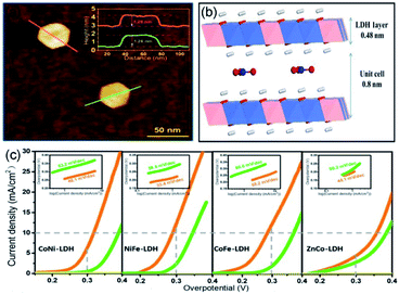 | ||
| Fig. 4 (a) AFM image and the corresponding heights of individual LDH. (b) Schematic illustration of the interlayer spacing of single-unit-cell-thick LDH NS. (c) Polarization curves and Tafel plots of bimetallic LDH NS (orange line) and bulk LDH (green line). Reproduced from ref. 46. Copyright 2018, Springer Nature. | ||
Our group has applied a synthesis strategy, combining hydrothermal treatment, etching, and calcination, to synthesize nanoporous Zn-doped Co3O4 sheets with single-unit-cell thickness and lateral surfaces (NPCoO-UCSs, in which UCS denotes unit-cell-thick sheet) for efficient OER.44 Morphological characterization in Fig. 5a reveals that partial interconnecting NPCoO-UCSs stand on the Ti foil, which generated considerable lateral surfaces and many nanopores, and the HR-TEM image shows 0.2 nm interplanar spacing, which belongs to (004) plane of Co3O4.73 As seen in Fig. 5b, AFM image measurement shows that the heights of NPCoO-UCSs (0.84 ± 0.03 nm) are very close to that of single-unit-cell-thick (0.81 nm).74 The NPCoO arrays growing on Ti foils were directly used as electrochemical electrodes with a mass loading of 0.45 mg cm−2. To compare the OER performance of different UCS heights, the etching durations (0, 1.0, 1.5, 2.5, and 3 h) were controlled to obtain distinctive polarization curves and TOF values of NPCoO. Different from those control samples (CoO-0 h, NPCoO-1 h, NPCoO-1.5 h, NPCoO-2.5 h, and CoO-3 h), NPCoO-UCSs (prepared by 2 h etching) possessed more nanopores and oxygen vacancies, both of which can accelerate the transfer of intermediates and electrons, resulting in higher catalytic performance.75 In Fig. 5c and d the onset potential and overpotential (calculating from 10 mA cm−2) of NPCoO-UCSs in 0.1 M KOH are 1.369 and 0.172 V, respectively. Furthermore, the high activity of NPCoO-UCSs maintains 50![[thin space (1/6-em)]](https://www.rsc.org/images/entities/char_2009.gif) 000 s for OER and 500 h for overall water splitting without obviously attenuating.
000 s for OER and 500 h for overall water splitting without obviously attenuating.
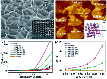 | ||
| Fig. 5 (a) Low-magnification and high-resolution TEM images of NPCoO-UCSs. (b) Top-view AFM image of NPCoO-UCSs, the measurable thickness close to the inserting 3D model of standard Co3O4 unit cell. (c) OER polarization curves of NPCoO-UCSs and other catalysts. (d) TOF vs. thickness curves of NPCoO-UCSs and other catalysts. Reproduced from ref. 44. Copyright 2018, Elsevier. | ||
3.3 STLEs for CO2RR
The high emissions of CO2 have impacted the climate, causing global warming and threatening sustainable development.76 CO2 electrochemical reduction into reusable low-carbon energy sources is an efficient route for sustainable recycling of carbon resources.77 Thus, recent investigations focused on developing suitable ultrathin electrocatalysts for CO2RR.78,79Our group has illustrated that Li-intercalation/exfoliation method allowed to obtain a monolayered SnS2 (M-SnS2) catalyst with excellent catalytic activity in CO2RR.48 As illustrated in Fig. 6a, AFM image and three different areas of corresponding heights showed an average thickness of 0.58 ± 0.04 nm, which is closing to that of the single-unit-cell thickness of SnS2, i.e., 0.59 nm (Fig. 6c). The FE of formate product specific to SnS2 monolayers is ∼100% at −0.8 V vs. RHE (Fig. 6b). In addition, the long-term durability of the STLE was proved by the 80 h of activity without an obvious decrease. We also studied the probable chemical pathways involved in the conversion of CO2 by DFT calculations. Fig. 6d–f, reveal that HCOO*, COOH*, and H* are the main competitive intermediates of the reactions leading to HCOOH, CO, and H2, respectively. Notably, it was found that the lowest Gibbs free energy (0.38 eV) belongs to HCOO* intermediate, which is formed on the (001) surface of M-SnS2. By contrary, the Gibbs free energy of HCOO* formation on bulk SnS2 was higher (0.79 eV). This phenomenon was mainly caused by the higher electron density of M-SnS2. Therefore, our group proposed a promising route to prepare an efficient and robust STLE for CO2 reduction.
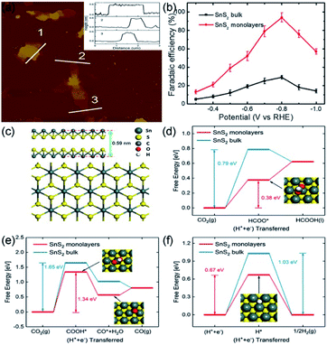 | ||
| Fig. 6 (a) AFM image and the corresponding heights and (b) FEs of formate over SnS2 monolayer at various applied potentials. (c) Atomic side and top models of single-unit-cell SnS2. (d and e) Free energy results of CO2 reduction to (d) HCOOH and (e) CO by SnS2 monolayer and bulk surface. (f) Free energy results of HER by SnS2 monolayer and bulk surface. Reproduced from ref. 48. Copyright 2018, Elsevier. | ||
3.4 STLEs for ZABs
Due to their high theoretical energy density (1084 W h kg−1), excellent safety, and low cost, ZABs are considered as one of the next-generation batteries to replace lithium-ion batteries.80,81 Oxygen evolution reaction (OER, which is the charge process) and oxygen reduction reaction (ORR, which is the discharge process) are the half-reactions occurring at the working electrode in ZABs.13 The overpotential of OER and half-wave/onset potential of ORR significantly affect the charge–discharge processes of ZABs. Yet, the use of commercial noble-metal-based materials, such as Pt/C, RuO2, and IrO2, as catalysts, restricts the large-scale development of ZABs. Developing cost-effective, high-performance, and robust catalysts to replace precious-metal-based catalysts is challenging, but it will be the key to the widespread application of ZABs. Recently, the transition metal oxides and hydroxides loaded on reduced graphene oxide (rGO) were successfully applied as STLEs for OER/ORR processes of ZABs due to the advantages of STLE structure already discussed.82,83 In these composite materials, the rGO acts as a current collector to accelerate the transfer of electrons.Wang et al. have proposed Br−-intercalation, NO3−-exchange, and exfoliation methods to gradually expand the interlayer distance of bulk CoNi-LDH for obtaining CoNi-NS monolayers.82 The delaminated CoNi-NSs were then flocculated and calcined together with GO to obtain CoNi-NS/rGO composites. As seen in Fig. 7a, the AFM image shows an average thickness of CoNi-NS monolayers of 0.7–0.8 nm, corresponding to the 0.8 nm of the CoNi-LDH monolayer. The single-unit-cell-thick structure of CoNi-NS monolayers and electrical conductivity of rGO endow the CoNi-NS/rGO composite with outstanding electrocatalytic activity and durability in ORR and OER under alkaline conditions. A homogeneous CoNi-NS/rGO ink, hybrid with Ketjenblack carbon, was dropped onto GCE with a loading of 0.48 mg cm−2. For OER charge process, an overpotential of 330 mV (vs. RHE) was obtained at 10 mA cm−2, for ORR discharge progress, the half-wave potential was of 0.85 V (vs. RHE), and the H2O2 yield was less than 7% (Fig. 7b and c). Benefitting from the effective properties of the bifunctional material, CoNi-NS/rGO exhibited stable rechargeability (more than 350 cycles) and a 300 mW cm−2 power density with a durable polarization gap (0.8 V at 10 mA cm−2) (Fig. 7d). Therefore, the authors proposed an efficient strategy to synthesize single-unit-cell-thick CoNi-NS/rGO composites for ZAB, especially since the delamination and flocculation methods are suitable for fabricating other types of STLEs. In addition, the substrate effect should also be considered for explaining the changes of intrinsic activity. As reported by Wang et al.,82 the rGO substrate, acting as a current collector, accelerates the electron transfer during the charge–discharge process of zinc-air batteries with CoNi-NS/rGO. Uosaki et al. find that the interaction between monolayer h-BN and the Au substrate facilitates the binding and activation of O2 molecules, and thereby significantly reduces the overpotential of oxygen reduction reaction.83
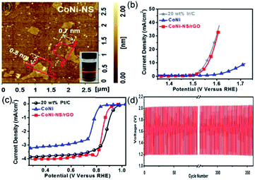 | ||
| Fig. 7 (a) AFM image of CoNi-NS and photograph of CoNi-NS suspension. Polarization curves of CoNi-NS/rGO, CoNi, and commercial catalysts for (b) OER and (c) ORR. (d) Charge and discharge cycling curves of CoNi-NS/rGO at 10 mA cm−2. Reproduced from ref. 82. Copyright 2019, Elsevier. | ||
Li et al. reported a facile and continuous method to synthesize layered Co3O4/nitrogen-doped rGO (Co3O4/N-rGO) composite, which can be assembled and knitted into flexible and wearable ZAB. In addition, the wearable device was made of low-cost materials, i.e., zinc wire, chiffon band, and carbon fibers.84 As shown in Fig. 8a, AFM image reveals that the thickness of Co3O4 nanosheets is 0.8 nm, corresponding to the single-unit-cell-thick of Co3O4 (0.81 nm). Noteworthy, compared with Pt/C and RuO2, Co3O4/N-rGO exhibited better ORR and OER performances, i.e., lower half-wave potential E1/2 (0.79 V vs. RHE) for ORR and overpotential Ej=10 (490 mV vs. RHE) for OER (Fig. 8b and c). Moreover, the charge–discharge potentials of ZAB appropriate for polarization curves, indicating better rechargeability of the novel composite material. Additionally, because the layered structure enlarged the surface-to-surface contact between Co3O4/N-rGO and the electrode, the cycling stability of ZAB showed a better rechargeability without obvious potential gap increase than the Pt/C + RuO2 catalyst. As a result, the charge–discharge potentials of the two catalysts approximated 2.0 V (Co3O4/N-rGO) and 1.2 V (Pt/C + RuO2) within 75 cycles for 25 h, respectively (Fig. 8d). The outcomes of that article are promising for ZAB applications in wearable electronics.
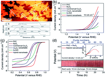 | ||
| Fig. 8 (a) AFM image and the corresponding height profiles of CO3O4 NS. (b and c) Linear sweep voltammetry curves of Co3O4/N-rGO, Co3O4-NS, N-rGO, commerical Co3O4, RuO2, and Pt/C. (d) Charge and discharge cycling curves of Co3O4/N-rGO and electrochemical impedance spectroscopy (EIS) spectrum of ZAB. Reproduced from ref. 84. Copyright 2018, Wiley-VCH. | ||
4. Conclusions and perspectives
STLEs (layer thickness generally less than 1.0 nm) are excellent candidates for commercial applications based on electrolytic processes. This minireview summarizes the latest strategies applied for the synthesis of STLEs and their applications in various fields. For STLE synthesis, both liquid exfoliation and thermal treatments under autogeneous pressure are considered as efficient strategies to fabricate high-performance STLEs. Liquid exfoliation approach is a facile way, allowing to overcome the weak forces between adjacent layers to separate them into individual layers; the thermal exfoliation approach depends on the optimized reaction parameters to produce STLEs efficiently. The catalytic activity of STLEs is maximized by the high surface area and vacancies, which increase the amount of active sites.However, despite the progress made in the synthesis of STLEs, their widespread application is still narrow. In this minireview, we attempt to identify those limitations and succinctly present them, as follows. (1) To obtain STLEs, liquid exfoliation and thermal processes are associated with noise and safety risks, respectively. More importantly, some reaction mechanisms and conditions take insufficient account of preparing monolayered electrocatalysts, such as the multi-step thermally exfoliation methods requiring time-consuming (typically, more than 10 h) solvothermal/hydrothermal procedure and high-temperature (typically, more than 250 °C) calcination, which are uneconomic for large-scale achieving STLEs. Besides, liquid exfoliation methods are unsuitable for exfoliating multilayer electrocatalysts in which the structural integrity of the assembly is maintained by strong interactions. Therefore, alternative strategies, such as chemical vapor deposition and epitaxial growth, should be adopted to go further into the preparation of a wide range of STLEs. (2) Regarding the application, although remarkable pioneering works have devoted efforts to STLEs, the challenges are related to the stability of STLEs, which remains controversial, due to that the single-unit-cell-thick structure will more easily transform into other characteristics during the whole reaction process. In addition, the performance of STLEs highly depends on the monolayer thickness and number of vacancies, and thus a degree of uncertainty over the relationship between performance and structure still exists. Thus, more advanced characterization techniques and DFT calculations are needed to shed more light on this relationship. Yet, despite all these challenges, STLEs have proven to have excellent electrochemical properties due to the suppressed agglomeration of particles and large amounts of active sites exposed, which encourage the researches in the area.
Conflicts of interest
There are no conflicts to declare.Acknowledgements
This work was financially supported by National Key R&D Program of China (2017YFA0700104), National Natural Science Foundation of China (21601136, 51971157 and 51761165012), Tianjin Science Fund for Distinguished Young Scholars (19JCJQJC61800), and Science & Technology Development Fund of Tianjin Education Commission for Higher Education (2018KJ126).Notes and references
- W. Ma, X. Liu, C. Li, H. Yin, W. Xi, R. Liu, G. He, X. Zhao, J. Luo and Y. Ding, Adv. Mater., 2018, 30, 1801152 CrossRef PubMed.
- S. Shen, X. Peng, L. Song, Y. Qiu, C. Li, L. Zhuo, J. He, J. Ren, X. Liu and J. Luo, Small, 2019, 15, 1902229 CrossRef PubMed.
- F. Lü, H. Bao, Y. Mi, Y. Liu, J. Sun, X. Peng, Y. Qiu, L. Zhuo, X. Liu and J. Luo, Sustainable Energy Fuels, 2020, 4, 1012–1028 RSC.
- M. Jiang, J. Li, J. Li, Y. Zhao, L. Pan, Q. Cao, D. Wang and Y. Du, Nanoscale, 2019, 11, 9654–9660 RSC.
- X. Miao, S. Zhou, L. Wu, J. Zhao and L. Shi, ACS Sustainable Chem. Eng., 2018, 6, 12337–12342 CrossRef CAS.
- C. Guan, W. Xiao, H. Wu, X. Liu, W. Zang, H. Zhang, J. Ding, Y. P. Feng, S. J. Pennycook and J. Wang, Nano Energy, 2018, 48, 73–80 CrossRef.
- R. Wang, F. Kapteijn and J. Gascon, Chem.–Asian J., 2019, 14, 3452–3461 CrossRef CAS PubMed.
- M. Li, F. Luo, Q. Zhang, Z. Yang and Z. Xu, J. Catal., 2020, 381, 395–401 CrossRef CAS.
- L. Fu, F. Yang, G. Cheng and W. Luo, Nanoscale, 2018, 10, 1892–1897 RSC.
- S. Geng, W. Yang and Y. S. Yu, J. Catal., 2019, 375, 441–447 CrossRef CAS.
- X. Wang, Y. Zheng, W. Sheng, Z. J. Xu, M. Jaroniec and S.-Z. Qiao, Mater. Today, 2020 DOI:10.1016/j.mattod.2019.12.003.
- H. Liu, X. Peng and X. Liu, ChemElectroChem, 2018, 5, 2963–2974 CrossRef CAS.
- S. Li, C. Cheng, X. Zhao, J. Schmidt and A. Thomas, Angew. Chem., Int. Ed., 2018, 57, 1856–1862 CrossRef CAS PubMed.
- S. Clark, A. R. Mainar, E. Iruin, L. C. Colmenares, J. A. Blázquez, J. R. Tolchard, Z. Jusys and B. Horstmann, Adv. Energy Mater., 2020, 10, 1903470 CrossRef CAS.
- P. De Luna, R. Quintero-Bermudez, C.-T. Dinh, M. B. Ross, O. S. Bushuyev, P. Todorović, T. Regier, S. O. Kelley, P. Yang and E. H. Sargent, Nat. Catal., 2018, 1, 103–110 CrossRef CAS.
- X. Liu, H. Yang, J. He, H. Liu, L. Song, L. Li and J. Luo, Small, 2018, 14, 1704049 CrossRef PubMed.
- S. Dou, L. Tao, R. Wang, S. El Hankari, R. Chen and S. Wang, Adv. Mater., 2018, 30, 1705850 CrossRef PubMed.
- P. M. Shafi, N. Joseph, A. Thirumurugan and A. C. Bose, Chem. Eng. J., 2018, 338, 147–156 CrossRef CAS.
- S. Shrestha, B. Wang and P. Dutta, Adv. Colloid Interface Sci., 2020, 279, 102162 CrossRef CAS PubMed.
- H. Chem Soc RevZhang, M. Chhowalla and Z. Liu, Chem. Soc. Rev., 2018, 47, 3015–3017 RSC.
- J. Liu, X. Bai, Q. Liu, R. Chen, X. Jing, B. Li, R. Li and J. Wang, J. Electrochem. Soc., 2018, 165, A784–A792 CrossRef CAS.
- F. A. Geenen, K. van Stiphout, A. Nanakoudis, S. Bals, A. Vantomme, J. Jordan-Sweet, C. Lavoie and C. Detavernier, J. Appl. Phys., 2018, 123, 075303 CrossRef.
- Y. Li, J. Yin, L. An, M. Lu, K. Sun, Y. Q. Zhao, F. Cheng and P. Xi, Nanoscale, 2018, 10, 6581–6588 RSC.
- Z. Liu, S. Zhang, H. Lin, M. Zhao, H. Yao, L. Zhang, W. Peng and Y. Chen, Biomaterials, 2018, 155, 54–63 CrossRef CAS PubMed.
- B. Li, C. Lai, L. Qin, C. Chu, M. Zhang, S. Liu, X. Liu, H. Yi, J. He, L. Li, M. Li and L. Chen, Adv. Colloid Interface Sci., 2020, 560, 701–713 CrossRef CAS PubMed.
- L. Zhang, B. Liu, N. Zhang and M. Ma, Nano Res., 2017, 11, 323–333 CrossRef.
- K. N. Dinh, P. Zheng, Z. Dai, Y. Zhang, R. Dangol, Y. Zheng, B. Li, Y. Zong and Q. Yan, Small, 2018, 14, 1703257 CrossRef PubMed.
- D. Esrafilzadeh, A. Zavabeti, R. Jalili, P. Atkin, J. Choi, B. J. Carey, R. Brkljača, A. P. O'Mullane, M. D. Dickey, D. L. Officer, D. R. MacFarlane, T. Daeneke and K. Kalantar-Zadeh, Nat. Commun., 2019, 10, 865 CrossRef PubMed.
- X. Li, Z. Liu, L. Song, D. Wang and Z. Zhang, Electrochim. Acta, 2018, 263, 561–569 CrossRef CAS.
- T. I. Kim, I. J. Park and S. Y. Choi, Nano Lett., 2020, 20, 3740–3746 CrossRef CAS PubMed.
- M. Luo, Y. Yang, Y. Sun, Y. Qin, C. Li, Y. Li, M. Li, S. Zhang, D. Su and S. Guo, Mater. Today, 2019, 23, 45–56 CrossRef CAS.
- K. ZHAO, W. Zhu, S. Liu, X. Wei and Z. He, Nanoscale Adv., 2020, 2, 536–562 RSC.
- H. Zhang, ACS Nano, 2015, 9, 9451–9469 CrossRef CAS PubMed.
- C. Tan, X. Cao, X. J. Wu, Q. He, J. Yang, X. Zhang, J. Chen, W. Zhao, S. Han, G. H. Nam, M. Sindoro and H. Zhang, Chem. Rev., 2017, 117, 6225–6331 CrossRef CAS PubMed.
- J. Xiong, P. Song, J. Di and H. Li, Appl. Catal., B, 2019, 256, 117788 CrossRef CAS.
- J. Lai and S. Guo, Small, 2017, 13, 1702156 CrossRef PubMed.
- W. Zhang and K. Zhou, Small, 2017, 13, 1700806 CrossRef PubMed.
- J. Di, C. Yan, A. D. Handoko, Z. W. Seh, H. Li and Z. Liu, Mater. Today, 2018, 21, 749–770 CrossRef CAS.
- X. Ge, Z. Xia and S. Guo, Adv. Funct. Mater., 2019, 29, 1900318 CrossRef.
- K. V. Sreekanth, S. Sreejith, S. Han, A. Mishra, X. Chen, H. Sun, C. T. Lim and R. Singh, Nat. Commun., 2018, 9, 369 CrossRef PubMed.
- J. Xu, X. Chen, Y. Xu, Y. Du and C. Yan, Adv. Mater., 2019, 32, 1806461 CrossRef PubMed.
- D. Li, S. Hao, G. Xing, Y. Li, X. Li, L. Fan and S. Yang, J. Am. Chem. Soc., 2019, 141, 3480–3488 CrossRef CAS PubMed.
- M. Golalikhani, Q. Lei, R. U. Chandrasena, L. Kasaei, H. Park, J. Bai, P. Orgiani, J. Ciston, G. E. Sterbinsky, D. A. Arena, P. Shafer, E. Arenholz, B. A. Davidson, A. J. Millis, A. X. Gray and X. X. Xi, Nat. Commun., 2018, 9, 2206 CrossRef CAS PubMed.
- X. Liu, W. Xi, C. Li, X. Li, J. Shi, Y. Shen, J. He, L. Zhang, L. Xie, X. Sun, P. Wang, J. Luo, L.-M. Liu and Y. Ding, Nano Energy, 2018, 44, 371–377 CrossRef CAS.
- Y. Jin, L. Dang, H. Zhang, C. Song, Q. Lu and F. Gao, Chem. Eng. J., 2017, 326, 292–297 CrossRef CAS.
- R. Gao and D. Yan, Nano Res., 2018, 11, 1883–1894 CrossRef CAS.
- S. Su, Q. Zhou, Z. Zeng, D. Hu, X. Wang, M. Jin, X. Gao, R. Notzel, G. Zhou, Z. Zhang and J. Liu, ACS Appl. Mater. Interfaces, 2018, 10, 8026–8035 CrossRef CAS PubMed.
- J. He, X. Liu, H. Liu, Z. Zhao, Y. Ding and J. Luo, J. Catal., 2018, 364, 125–130 CrossRef CAS.
- Y. Wang, D. Yan, S. El Hankari, Y. Zou and S. Wang, Adv. Sci., 2018, 5, 1800064 CrossRef PubMed.
- S. Gao, Z. Sun, W. Liu, X. Jiao, X. Zu, Q. Hu, Y. Sun, T. Yao, W. Zhang, S. Wei and Y. Xie, Nat. Commun., 2017, 8, 14503 CrossRef CAS PubMed.
- L. Liang, H. Cheng, F. Lei, J. Han, S. Gao, C. Wang, Y. Sun, S. Qamar, S. Wei and Y. Xie, Angew. Chem., Int. Ed., 2015, 54, 12004–12008 CrossRef CAS PubMed.
- G. Liu, J. Li, J. Fu, G. Jiang, G. Lui, D. Luo, Y. P. Deng, J. Zhang, Z. P. Cano, A. Yu, D. Su, Z. Bai, L. Yang and Z. Chen, Adv. Mater., 2019, 31, 1806761 Search PubMed.
- Y. Wang, Y. Zhang, Z. Liu, C. Xie, S. Feng, D. Liu, M. Shao and S. Wang, Angew. Chem., Int. Ed., 2017, 56, 5867–5871 CrossRef CAS PubMed.
- J. Di, J. Xia, M. F. Chisholm, J. Zhong, C. Chen, X. Cao, F. Dong, Z. Chi, H. Chen, Y. X. Weng, J. Xiong, S. Z. Yang, H. Li, Z. Liu and S. Dai, Adv. Mater., 2019, 31, 1807576 CrossRef PubMed.
- J. Hou, S. Cao, Y. Wu, F. Liang, Y. Sun, Z. Lin and L. Sun, Nano Energy, 2017, 32, 359–366 CrossRef CAS.
- X. Jiao, Z. Chen, X. Li, Y. Sun, S. Gao, W. Yan, C. Wang, Q. Zhang, Y. Lin, Y. Luo and Y. Xie, J. Am. Chem. Soc., 2017, 139, 7586–7594 CrossRef CAS PubMed.
- J. Di, C. Chen, S. Z. Yang, S. Chen, M. Duan, J. Xiong, C. Zhu, R. Long, W. Hao, Z. Chi, H. Chen, Y. X. Weng, J. Xia, L. Song, S. Li, H. Li and Z. Liu, Nat. Commun., 2019, 10, 2840 CrossRef PubMed.
- H. Huang, C. Zhou, X. Jiao, H. Yuan, J. Zhao, C. He, J. Hofkens, M. B. Roeffaers, J. Long and J. A. Steele, ACS Catal., 2020, 10, 1439–1443 CrossRef CAS.
- J. Di, C. Chen, C. Zhu, M. Ji, J. Xia, C. Yan, W. Hao, S. Li, H. Li and Z. Liu, Appl. Catal., B, 2018, 238, 119–125 CrossRef CAS.
- C. K. Chua, Z. Sofer, O. Jankovský and M. Pumera, ChemPhysChem, 2015, 16, 769–774 CrossRef CAS PubMed.
- M. Q. Yang, Y. J. Xu, W. Lu, K. Zeng, H. Zhu, Q. H. Xu and G. W. Ho, Nat. Commun., 2017, 8, 14224 CrossRef CAS PubMed.
- B. Xu, P. He, H. Liu, P. Wang, G. Zhou and X. Wang, Angew. Chem., Int. Ed., 2014, 53, 2339–2343 CrossRef CAS PubMed.
- A. Jawaid, D. Nepal, K. Park, M. Jespersen, A. Qualley, P. Mirau, L. F. Drummy and R. A. Vaia, Chem. Mater., 2015, 28, 337–348 CrossRef.
- N. K. Oh, H. J. Lee, K. Choi, J. Seo, U. Kim, J. Lee, Y. Choi, S. Jung, J. H. Lee, H. S. Shin and H. Park, Chem. Mater., 2018, 30, 4658–4666 CrossRef CAS.
- X. Liu, J. He, S. Zhao, Y. Liu, Z. Zhao, J. Luo, G. Hu, X. Sun and Y. Ding, Nat. Commun., 2018, 9, 4365 CrossRef PubMed.
- L. Zhang, L. Han, H. Liu, X. Liu and J. Luo, Angew. Chem., Int. Ed., 2017, 56, 13694–13698 CrossRef CAS PubMed.
- H. Liu, X. Peng, X. Liu, G. Qi and J. Luo, ChemSusChem, 2019, 12, 1334–1341 CrossRef CAS PubMed.
- Y. Liu, C. Liang, J. Wu, T. Sharifi, H. Xu, Y. Nakanishi, Y. Yang, C. F. Woellne, A. Aliyan, A. A. Martí, B. Xie, R. Vajtai, W. Yang and P. M. Ajayan, Adv. Mater. Interfaces, 2018, 5, 1700895 CrossRef.
- W. Xu, S. Li, S. Zhou, J. K. Lee, S. Wang, S. G. Sarwat, X. Wang, H. Bhaskaran, M. Pasta and J. H. Warner, ACS Appl. Mater. Interfaces, 2018, 10, 4630–4639 CrossRef CAS PubMed.
- C. Zhang, H. Liu, J. He, G. Hu, H. Bao, F. Lü, L. Zhuo, J. Ren, X. Liu and J. Luo, Electrochem. Commun., 2019, 55, 10511–10514 CAS.
- D. Wang, H. Li, N. Du, Z. Lang, T. Hu and W. Hou, Adv. Colloid Interface Sci., 2019, 541, 183–191 CrossRef CAS PubMed.
- Q. Zhou, Z. Shen, C. Zhu, J. Li, Z. Ding, P. Wang, F. Pan, Z. Zhang, H. Ma, S. Wang and H. Zhang, Adv. Mater., 2018, 30, 1800140 CrossRef PubMed.
- K. Jiao, Z. Kang, B. Wang, S. Jiao, Y. Jiang and Z. Hu, Electroanalysis, 2018, 30, 525–532 CrossRef CAS.
- X. He, S. Z. Luan, L. Wang, R. Y. Wang, P. Du, Y. Y. Xu, H. J. Yang, Y. G. Wang, K. Huang and M. Lei, Mater. Lett., 2019, 244, 78–82 CrossRef CAS.
- W. Xu, F. Lyu, Y. Bai, A. Gao, J. Feng, Z. Cai and Y. Yin, Nano Energy, 2018, 43, 110–116 CrossRef CAS.
- Y. Huo, X. Peng, X. Liu, H. Li and J. Luo, ACS Appl. Mater. Interfaces, 2018, 10, 12618–12625 CrossRef CAS PubMed.
- S. Shen, J. He, X. Peng, W. Xi, L. Zhang, D. Xi, L. Wang, X. Liu and J. Luo, J. Mater. Chem. A, 2018, 6, 18960–18966 RSC.
- F. Lü, G. Qi, X. Liu, C. Zhang, R. Guo, X. Peng, J. He and J. Luo, Electrochem. Commun., 2019, 103, 127–132 CrossRef.
- X. Peng, Y. Chen, Y. Mi, L. Zhuo, G. Qi, J. Ren, Y. Qiu, X. Liu and J. Luo, Inorg. Chem., 2019, 58, 8910–8914 CrossRef CAS PubMed.
- L. Wang, Y. Wang, M. Wu, Z. Wei, C. Cui, M. Mao, J. Zhang, X. Han, Q. Liu and J. Ma, Small, 2018, 14, 1800737 CrossRef PubMed.
- W. Wan, X. Liu, H. Li, X. Peng, D. Xi and J. Luo, Appl. Catal., B, 2019, 240, 193–200 CrossRef CAS.
- T. Wang, J. Wu, Y. Liu, X. Cui, P. Ding, J. Deng, C. Zha, E. Coy and Y. Li, Energy Storage Materials, 2019, 16, 24–30 CrossRef.
- K. Uosaki, G. Elumalai, H. Noguchi, T. Masuda, A. Lyalin, A. Nakayama and T. Taketsugu, J. Am. Chem. Soc., 2014, 136, 6542–6545 CrossRef CAS PubMed.
- Y. Li, C. Zhong, J. Liu, X. Zeng, S. Qu, X. Han, Y. Deng, W. Hu and J. Lu, Adv. Mater., 2018, 30, 1703657 CrossRef PubMed.
| This journal is © The Royal Society of Chemistry 2020 |


