Cu/TiO2 octahedral-shell photocatalysts derived from metal–organic framework@semiconductor hybrid structures†
Rui
Li‡
,
Sikai
Wu‡
,
Xueying
Wan‡
,
Hangxun
Xu
* and
Yujie
Xiong
*
Hefei National Laboratory for Physical Sciences at the Microscale, iChEM (Collaborative Innovation Center of Chemistry for Energy Materials), Hefei Science Center (CAS), and School of Chemistry and Materials Science, University of Science and Technology of China, Hefei, Anhui 230026, P. R. China. E-mail: yjxiong@ustc.edu.cn; hxu@ustc.edu.cn; Tel: +86-551-63606657
First published on 5th November 2015
Abstract
The insertion of metal cocatalysts into semiconductor photocatalysts, which can promote electron–hole separation and provide additional reaction sites, is a popularly used approach to improve photocatalytic efficiency. In this article, we demonstrate a facile synthetic method for Cu/TiO2 photocatalysts with hollow structures by templating on metal–organic frameworks (MOFs). The Cu3(BTC)2 MOF octahedral microcrystals enwrapped by TiO2 shells serve as a Cu precursor for the in situ generation of Cu nanoparticles on the TiO2 photocatalyst. This method offers the versatility to tailor the photocatalyst configurations (including compositions, crystal phases, cocatalyst sizes, etc.) by simply altering the treatment conditions on MOF cores (e.g., room-temperature etching, simultaneous etching and reduction, and high-temperature calcination reduction). Enabled by the varied configurations, the synthesized octahedral-shell photocatalysts exhibit remarkably different performances in charge separation and photocatalytic hydrogen production, allowing the identification of an optimal design for photocatalysis.
1. Introduction
Metal–organic frameworks (MOFs) are a class of porous materials that offer tunable pore textures and high specific surface areas as well as diverse geometries by controlling the assembly of inorganic and organic building blocks.1–4 Owing to their porous structures, MOFs have been employed as either templates or precursors for their derived materials as they can be facilely removed by mild acid etching or calcination after synthesis.5,6 Previously, MOF-derived materials have been mainly based on porous carbon or metal oxides by taking advantage of the inherent porosity in MOFs.7–10 However, the development of hollow micro- and nanostructures by replicating the geometric features of MOFs is quite rare.11Hollow structures have attracted significant attention because of their irreplaceable architectural features and widespread applications in many fields such as catalysis, drug delivery, photonic devices and energy storage.12–15 Driven by strong demand, various methods have been developed for the fabrication of hollow structures, among which hard templating on carbon, silica and polymer spheres is one of the most effective approaches to the synthesis of uniform shells.16–19 In the scheme of hard templating, the geometries of the resultant shells mainly inherit from the shapes of mother templates.
In this article, we report a new class of octahedral-shaped TiO2 hollow structures composed of highly crystalline anatase-phase TiO2 nanoparticles by replicating the morphology of Cu3(BTC)2 (BTC = benzene-1,3,5-tricarboxylate) MOF microcrystals. Based on the previously developed Cu3(BTC)2@TiO2 core–shell structure,20 the Cu3(BTC)2 cores can be mildly etched by ascorbic acid (AA) at room temperature to leave TiO2 octahedral shells behind (Scheme 1). This Cu-based MOF not only provides a high-quality and uniform sacrificial template, but also can serve as a Cu source for the preparation of Cu/TiO2 hybrid structures by simultaneously reducing the released Cu2+ cations using AA in ethylene glycol (EG) solvent at 140 °C. EG is employed as the solvent to slow the oxidation of the Cu nanoparticles decorated on the TiO2 shells. In a parallel scheme, the Cu3(BTC)2 cores can be removed by high-temperature calcination which allows the reduction of Cu2+ cations into Cu nanoparticles in the solid phase. We have further implemented the obtained TiO2-based octahedral nanoshells in photocatalytic hydrogen production. The AA-reduced Cu/TiO2 hybrid structures exhibit enhanced charge separation and hydrogen production performance due to the functioning of the Cu cocatalyst, while the calcined Cu/TiO2 sample does not show comparable photocatalytic activity attributed to the production of carbon residues, crystal phase transition and increased Cu particle size by high-temperature treatment.
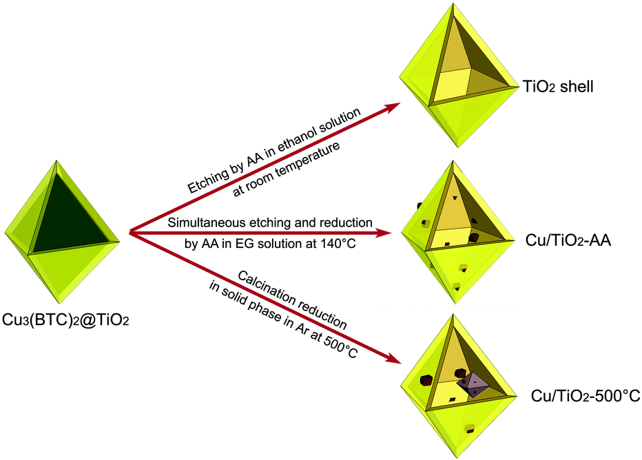 | ||
| Scheme 1 Schematic illustration for the synthetic approaches used in this work for various TiO2-based hollow-shell photocatalysts: TiO2 shell, Cu/TiO2-AA and Cu/TiO2-500 °C. | ||
2. Experimental
2.1 Synthesis of Cu3(BTC)2@TiO2 core–shell structure
The Cu3(BTC)2@TiO2 core–shell structure was synthesized by following our previously developed protocol.202.2 Synthesis of the TiO2 shell sample via room-temperature etching
The as-synthesized Cu3(BTC)2@TiO2 sample was dispersed in 8 mL of 0.025 M AA ethanol solution. After being shaken for 5 s, the solution was centrifuged at 5![[thin space (1/6-em)]](https://www.rsc.org/images/entities/char_2009.gif) 000 rpm. The precipitate was then redispersed in 8 mL of 0.125 M AA ethanol solution. After being shaken for 5 s, the sample was separated via 5
000 rpm. The precipitate was then redispersed in 8 mL of 0.125 M AA ethanol solution. After being shaken for 5 s, the sample was separated via 5![[thin space (1/6-em)]](https://www.rsc.org/images/entities/char_2009.gif) 000 rpm centrifugation again. Such a procedure was repeated several times until the blue color completely disappeared from the solution. Subsequently, the sample was washed with ethanol 2 times. Finally, the obtained powder was dried at 60 °C in a vacuum. We named this sample as the “TiO2 shell”.
000 rpm centrifugation again. Such a procedure was repeated several times until the blue color completely disappeared from the solution. Subsequently, the sample was washed with ethanol 2 times. Finally, the obtained powder was dried at 60 °C in a vacuum. We named this sample as the “TiO2 shell”.
2.3 Synthesis of the Cu/TiO2-AA hybrid structure via simultaneous etching and reduction
In a standard process, the as-synthesized Cu3(BTC)2@TiO2 sample (7 mg) and 334 mg poly(vinyl pyrrolidone) (PVP, MW = 55![[thin space (1/6-em)]](https://www.rsc.org/images/entities/char_2009.gif) 000) were dispersed in 10 mL EG, which was then heated under magnetic stirring at 140 °C in a three-necked round-bottom flask and deoxygenated using an Ar stream. Subsequently, 3 mL of EG containing 13.2 mg AA (0.025 M) was injected into the solution above with a syringe pump at 0.25 mL min−1. Afterwards the product was isolated by centrifugation, washed with 0.025 M AA ethanol solution several times and with ethanol 2 times, and then dried at 60 °C in a vacuum. To distinguish this sample from the one prepared via calcination, we name it as “Cu/TiO2-AA”. Inductively-coupled plasma mass spectrometry (ICP-MS) analysis indicated that 52.86 wt% Cu was loaded into the entire sample.
000) were dispersed in 10 mL EG, which was then heated under magnetic stirring at 140 °C in a three-necked round-bottom flask and deoxygenated using an Ar stream. Subsequently, 3 mL of EG containing 13.2 mg AA (0.025 M) was injected into the solution above with a syringe pump at 0.25 mL min−1. Afterwards the product was isolated by centrifugation, washed with 0.025 M AA ethanol solution several times and with ethanol 2 times, and then dried at 60 °C in a vacuum. To distinguish this sample from the one prepared via calcination, we name it as “Cu/TiO2-AA”. Inductively-coupled plasma mass spectrometry (ICP-MS) analysis indicated that 52.86 wt% Cu was loaded into the entire sample.
2.4 Synthesis of the Cu/TiO2-500 °C hybrid structure via calcination reduction in the solid phase
The as-synthesized Cu3(BTC)2@TiO2 sample was calcined in Ar at a rate of 3 °C min−1 to 200 °C for 2 h, and then at a rate of 2 °C min−1 to 500 °C for another 3 h, yielding a Cu/TiO2 hybrid structure. ICP-MS analysis indicated that 31.00 wt% Cu was loaded into the entire sample. We named this sample as “Cu/TiO2-500 °C”.2.5 Characterization
XRD patterns were recorded on a Philips X'Pert Pro Super diffractometer with Cu Kα radiation (λ = 1.54178 Å). The concentrations of metals were measured with a Thermo Scientific PlasmaQuad 3 ICP-MS after dissolving the samples with a mixture of HCl and HNO3 (3![[thin space (1/6-em)]](https://www.rsc.org/images/entities/char_2009.gif) :
:![[thin space (1/6-em)]](https://www.rsc.org/images/entities/char_2009.gif) 1, volume ratio). UV-vis diffuse reflectance data were recorded in the spectral range of 220–800 nm with a Shimadzu SolidSpec-3700 spectrophotometer. X-ray photoelectron spectra (XPS) were recorded on a Thermo ESCALab 250 X-ray photoelectron spectrometer, using nonmonochromatized Al-Kα X-ray as the excitation source.
1, volume ratio). UV-vis diffuse reflectance data were recorded in the spectral range of 220–800 nm with a Shimadzu SolidSpec-3700 spectrophotometer. X-ray photoelectron spectra (XPS) were recorded on a Thermo ESCALab 250 X-ray photoelectron spectrometer, using nonmonochromatized Al-Kα X-ray as the excitation source.
Prior to electron microscopy characterization, a drop of the aqueous suspension of particles was placed on a piece of carbon-coated copper grid or silicon wafer and dried under ambient conditions. Transmission electron microscopy (TEM) and high-resolution transmission electron microscopy (HRTEM) images were taken on a JEOL JEM-2100F field-emission high-resolution transmission electron microscope operated at 200 kV. Energy-dispersive X-ray spectroscopy (EDS) was used to determine the elemental compositions of the sample on the JEOL JEM-2100F. The EDS data were processed with the Inca Microanalysis Suite. The EDS sample was prepared by placing the particles on a Ni/C grid. SEM images were taken on a FEI Sirion 200 field-emission scanning electron microscope operated at 5 kV.
2.6 Photoelectrochemical measurements
The measurements were carried out in a three-electrode, single-compartment quartz cell. All the experiments were performed at room temperature in a 0.5 M Na2SO4 electrolyte (100 mL, pH = 6.6) deoxygenated with an Ar stream. The working electrode was prepared by depositing the as-prepared samples on indium tin oxide (ITO) glass (1 cm2 in deposition area). The suspension for the deposition was 200 μL ethanol containing 1 mg of the synthesized samples. The counter and reference electrodes were platinum gauze and Ag/AgCl, respectively. The photoresponses of the prepared photoelectrodes were operated by sweeping the potential from 0 to 1.0 V (vs. Ag/AgCl) at a sweep rate of 10 mV s−1 under chopped UV-light irradiation of a 300 W Xe lamp (λ < 400 nm, Perfect Light). The photocurrents were recorded on a CHI 660D electrochemical station (Shanghai Chenhua, China).2.7 Photocatalytic hydrogen production measurements
To investigate the photocatalytic hydrogen production performance of the samples, 10 mg photocatalysts were added to a 10 mL aqueous solution (10% methanol). The mixture was deoxygenated using an Ar stream to eliminate air. Then the suspension was illuminated with the same light source as that for the photoelectrochemical measurements. The power density of UV light was measured to be 3 mW cm−2. The photocatalytic reaction time was 4 hours. The rates of photocatalytic hydrogen production were determined using a gas chromatograph (GC, 7890A, thermal conductivity detector (TCD), Ar carrier, Agilent). Three replicates were collected for each sample with a relative error <10%.3. Results and discussion
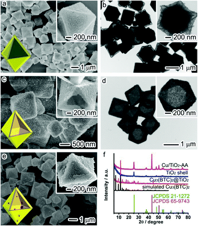
The precursor Cu3(BTC)2@TiO2 was firstly prepared by following the solvothermal method in our previous report.20 SEM and TEM images (Fig. 1a and b) show that the resulting sample possesses a core@shell structure with an octahedral Cu3(BTC)2 core at an average size of 1 μm and a TiO2 shell with a thickness of ca. 210 nm. Most MOFs with weak metal–ligand coordination bonds are vulnerable to water molecules and particularly sensitive to acidic or alkaline conditions.21 A typical example is the Cu3(BTC)2 used in this work which can be easily collapsed in an acidic environment. For this reason, we intentionally disperse the as-synthesized Cu3(BTC)2@TiO2 sample in the ethanol solution of AA – a type of weak acid, and allow the Cu3(BTC)2 to be completely etched by AA in the repeated procedures of shaking and centrifugation. During this etching process, the color of the suspension turns from blue to bright grass green and then finally yellow. Fig. 1c and d show SEM and TEM images of the sample obtained from this simple and straightforward etching method. These images clearly demonstrate that the Cu3(BTC)2 cores have been completely removed by acid etching, leading to the formation of perfect octahedral-shaped TiO2 shells (namely, TiO2 shell).To elucidate the role of a weak acid in the etching process, we carried out control experiments using a series of different etchants such as water, HCl and 10% HCl solution to etch Cu3(BTC)2 cores, respectively. TEM images (Fig. S1†) show that the Cu3(BTC)2 cores cannot be completely decomposed when water is used. In the case of HCl as an etchant, the TiO2 shells are broken down to tiny TiO2 nanocrystals. In contrast, diluted HCl (10%) solution only partially damages the TiO2 shells. Therefore, the use of a weak acid as the etchant is critical for the complete removal of the Cu3(BTC)2 MOF cores while keeping the structures of the TiO2 shells intact.
The above results demonstrate that the use of a susceptible Cu-based MOF as a sacrificial template is a facile method for producing hollow structures with a uniform octahedral profile. Another unique feature of Cu3(BTC)2 that cannot be offered by other hard templates is to provide Cu sources during the etching process for the decoration of TiO2 shells with Cu nanoparticles. It is known that insertion of metal cocatalysts into a semiconductor photocatalyst can facilitate the electron–hole separation and provide additional reaction sites for photocatalysis. For this reason, we have further modified the protocol for the decoration of Cu nanoparticles on TiO2 shells. The key to this modification is to increase the reaction temperature to 140 °C for enhancing the reducing ability of AA as well as to use EG as a solvent to slow the oxidation of Cu nanoparticles. As a result, the Cu2+ ions released from the AA etching on Cu3(BTC)2 can be simultaneously reduced by AA to produce Cu nanoparticles when they penetrate through the TiO2 shells. As indicated by the SEM image (Fig. 1e), the TiO2 shells are well maintained and decorated with some Cu nanoparticles (namely, Cu/TiO2-AA hybrid structure).
The complete removal of Cu3(BTC)2 cores by AA acid etching and the formation of Cu nanoparticles by AA reduction have been fully examined by X-ray diffraction (XRD) comparison between the Cu3(BTC)2@TiO2 precursor and the TiO2 shell and the Cu/TiO2-AA products. As shown in Fig. 1f, the core–shell precursor is a hybrid structure between Cu3(BTC)2 and anatase TiO2 (JCPDS 21-1272). As the Cu3(BTC)2 is etched by AA at room temperature, the precursor can be transformed into pure anatase TiO2. Once the etching is conducted in EG solvent at 140 °C, the released Cu source can be reduced into face-centered cubic (fcc) Cu (JCPDS 65-9743) to form the Cu/TiO2 hybrid structure.
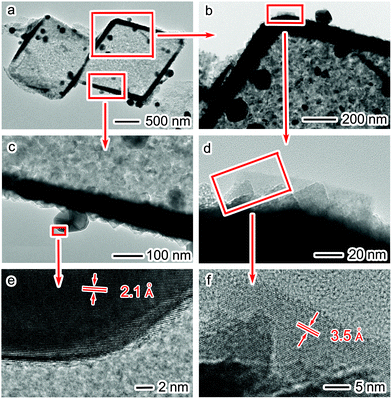
The decoration of Cu nanoparticles on TiO2 shells can be clearly observed under TEM examination. As revealed in Fig. 2a–d, Cu nanoparticles with sizes of 100–200 nm are evenly distributed on the walls of TiO2 shells. HRTEM images in Fig. 2e and f show the lattice fringes of TiO2 in the shells and Cu on the shells, respectively, indicating that the hybrid structures are composed of highly crystalline TiO2 and Cu nanoparticles. The lattice fringes with spacings of 2.1 Å can be assigned to the (111) crystal planes of Cu nanoparticles decorated on the shells (Fig. 2e), and those of 3.5 Å are indexed to the (101) crystal planes of anatase TiO2 nanocrystals in the shells (Fig. 2f). The energy-dispersive X-ray spectrum (EDS) (Fig. S2†) further confirms the compositions of this hybrid structure. In addition, the ratio of TiO2 to Cu is about 1![[thin space (1/6-em)]](https://www.rsc.org/images/entities/char_2009.gif) :
:![[thin space (1/6-em)]](https://www.rsc.org/images/entities/char_2009.gif) 1.4 as determined by ICP-MS.
1.4 as determined by ICP-MS.
To prove that the Cu nanoparticles are formed by etching and reducing Cu3(BTC)2, we have performed a control experiment by replacing the Cu3(BTC)2@TiO2 precursor with bare Cu3(BTC)2. Fig. S3a† shows the TEM image of the product obtained with AA in the EG solvent at 140 °C. It is clearly seen that the product consists of Cu nanoparticles at sizes of 100–200 nm, which are comparable to those of the Cu in the Cu/TiO2-AA hybrid structure. Their crystal phase is further confirmed by XRD (Fig. S3b†), in which all the peaks can be assigned to fcc Cu (JCPDS 65-9743).
Certainly the method of simultaneous etching and reduction is not the only approach to transform MOFs into metal nanoparticles. Previously, heat treatment has been demonstrated as another effective approach to decompose MOFs into metal/metal oxide materials.6,22 To demonstrate the niche of our “etching and reduction” approach, we have also employed calcination to treat the solid sample of the Cu3(BTC)2@TiO2 core–shell structure. It turns out that the heat treatment at temperatures below 500 °C cannot completely decompose the Cu3(BTC)2 cores. For this reason, we choose to calcine the core–shell particles at 500 °C in Ar for 5 h. Such a calcination process results in a color change from blue to black with a metallic luster, which is likely caused by the transformation of Cu3(BTC)2 cores into Cu and C.
SEM and TEM images (Fig. 3a–e) reveal that the TiO2 shells well maintain their morphology during the heat treatment. After calcination, the MOF cores disappear and instead a lot of aggregates of Cu nanoparticles are formed around the TiO2 shells (namely, the Cu/TiO2-500 °C hybrid structure). Apparently the quality of Cu nanoparticles obtained via this high-temperature treatment method is significantly lower than that in the Cu/TiO2-AA hybrid structure in terms of size distribution and dispersion, which is a typical drawback of high-temperature calcination. The ratio of TiO2 to Cu, as determined by ICP-MS, is about 1![[thin space (1/6-em)]](https://www.rsc.org/images/entities/char_2009.gif) :
:![[thin space (1/6-em)]](https://www.rsc.org/images/entities/char_2009.gif) 1.76. In comparison, the Cu content in the Cu/TiO2-AA hybrid structure is lower, as the conversion of etching-released Cu sources in solution into Cu nanoparticles is not as efficient as that by solid-phase calcination.
1.76. In comparison, the Cu content in the Cu/TiO2-AA hybrid structure is lower, as the conversion of etching-released Cu sources in solution into Cu nanoparticles is not as efficient as that by solid-phase calcination.
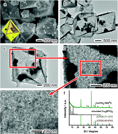 | ||
| Fig. 3 (a) SEM images, (b–e) TEM images, and (f) XRD patterns of the Cu/TiO2-500 °C hybrid structure. | ||
Although the TiO2 shells can maintain their morphology in this calcination method, their crystal phase has been slightly altered. The XRD pattern in Fig. 3f shows a slight phase transition within the shells, in which a newly emerging peak at 35.3° can be assigned to the (402) crystal face of the monoclinic TiO2 phase (JCPDS 46-1238). The other XRD peaks are indexed to anatase TiO2 (JCPDS 21-1272) and fcc Cu (JCPDS 65-9743), indicating that the Cu3(BTC)2 cores have been converted into Cu nanoparticles. Although both TiO2 and Cu are highly crystalline as revealed by XRD, it appears to be difficult to resolve their lattice fringes by HRTEM. This might be caused by the presence of carbon contaminants produced during the calcination process.
Despite the slight phase transition, the light absorption (λ < 400 nm) by TiO2 remains constant, as suggested by the UV-vis absorption spectra of the 3 different samples (Fig. 4). The comparable light absorption at λ < 400 nm would set up a platform for investigating the effect of Cu cocatalysts on photocatalysis under UV irradiation. In addition to the semiconductor light absorption, the UV-vis spectra also provide information on the surface plasmonic bands of Cu nanoparticles. The Cu/TiO2-AA sample exhibits a clear band centered at around 560 nm attributable to the surface plasmon of Cu nanoparticles. In comparison, the Cu plasmonic band in the Cu/TiO2-500 °C sample is obviously much broader, which is caused by the large size distribution and particle sintering during the high-temperature treatment.
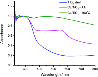 | ||
| Fig. 4 UV-vis diffuse reflectance spectra of the TiO2 shell, the Cu/TiO2-500 °C hybrid structure and the Cu/TiO2-AA hybrid structure. | ||
Prior to the evaluation of the cocatalyst effect on photocatalysis, one has to first examine the valence states of Cu in the Cu/TiO2 hybrid structures. The Cu/TiO2-AA and Cu/TiO2-500 °C samples exhibit similar XPS spectra for Cu 2p3/2 and Cu 2p1/2 (Fig. 5a and b). The binding energies of 932.5 eV for Cu 2p3/2 and 955 eV for Cu 2p1/2 suggest that Cu0 and/or Cu+ species exist in the Cu/TiO2.23 Although the shakeup satellite peak at 942 eV characteristic for Cu2+ has been observed in the samples, the Cu 2p3/2 peak at ∼935 eV for Cu2+ is not distinct.23,24 It indicates that only a very small portion of Cu species in the nanoparticles may have been oxidized, most likely occurring at the surface. As Cu 2p3/2 XPS can hardly differentiate Cu+ from Cu0, we have employed Cu LMM Auger spectra to characterize the Cu/TiO2-AA and Cu/TiO2-500 °C samples (Fig. 5c and d). The Cu LMM Auger kinetic energy at 916 eV for Cu/TiO2-AA indicates the presence of Cu+, while the kinetic energy at 919 eV for Cu/TiO2-500 °C can be ascribed to Cu0. This result suggests that the Cu nanoparticles formed by AA reduction are more susceptible to air oxidation. Cu nanoparticles without surface protection inevitably undergo surface oxidation when exposed to air. In the case of Cu/TiO2-500 °C, the presence of carbon on Cu nanoparticles may help suppress their surface oxidation. However, the contamination of Cu nanoparticles by carbon in Cu/TiO2-500 °C would be detrimental to the contact between Cu and TiO2 and reduce the efficacy of the cocatalyst in improving charge separation.
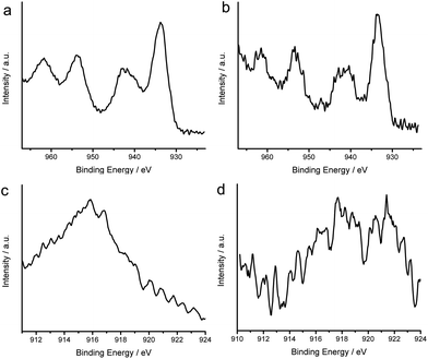 | ||
| Fig. 5 Cu 2P3/2 and 2P1/2 XPS spectra of (a) Cu/TiO2-AA and (b) Cu/TiO2-500 °C samples; Cu LMM high-resolution XPS spectra of (c) Cu/TiO2-AA and (d) Cu/TiO2-500 °C samples. | ||
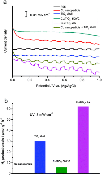
To assess the efficiency of charge separation, we have collected photocurrents from the photoelectrodes made of the derived TiO2-based samples with reference to commercial P25 under UV-light irradiation (Fig. 6a). The mixture of Cu nanoparticle (produced from AA etching and reduction on bare Cu3(BTC)2, Fig. S3†) and TiO2 shell samples is also used for comparison. With the comparable light absorption (as indicated by UV-vis absorption spectra in Fig. 4), the efficiencies of the various photocatalysts in charge separation are in the order of Cu/TiO2-AA hybrid structure > the mixture of Cu NPs and TiO2 shell > TiO2 shell ≈ P25 > Cu/TiO2-500 °C hybrid structure. As anticipated, the functioning of the Cu cocatalyst in the Cu/TiO2-AA hybrid structure has effectively suppressed the recombination of photoexcited electron–hole pairs, as the charge-carriers become trapped on the cocatalyst.23 In comparison, the physical mixture of two separate phases, the Cu nanoparticle and the TiO2 shell sample cannot achieve as good contact as the Cu/TiO2-AA. On the other hand, the Cu/TiO2-500 °C sample shows reduced efficiency in charge separation due to the existence of carbon residues between Cu and TiO2. Another drawback of this calcination approach is the slight TiO2 phase transition and Cu aggregation, which makes the efficiency of this sample even lower than the bare TiO2 shell. It is well recognized that anatase is the TiO2 phase with the highest efficiency for photocatalysis.25
Upon decoding the configuration-performance relationship, we further implement the TiO2-based samples in photocatalysis. In this study, we employ photocatalytic hydrogen production from a 10 vol% methanol solution as a model reaction. As demonstrated in Fig. 6b, the Cu/TiO2-AA hybrid structure exhibits the highest hydrogen production rate under UV light (62.16 μmol g−1 h−1) among all the samples. Note that bare Cu nanoparticles do not produce hydrogen in a control experiment.
4. Conclusions
In summary, we have synthesized a series of TiO2-based samples derived from MOF@TiO2 core–shell structures, whose configurations can be readily tailored by varying the treatment methods. This is the first time various novel octahedral-shaped TiO2 hollow shell structures and Cu/TiO2 hybrid structures based on MOF templates have been obtained. As compared with the widely used calcination approach, the simultaneous etching and reduction can better preserve the octahedral-shaped shells and crystal phase as well as prevent the formation of carbon residues and cocatalyst aggregation, which all help improve the efficiency of photocatalysis. The unique structure and improved photocatalytic activity demonstrate that MOFs can serve as ideal templates and sacrificial agents for the fabrication of functional polyhedral-shaped hollow shell structures.Acknowledgements
This work was financially supported by the 973 Program (no. 2014CB848900), NSFC (no. 21471141), Recruitment Program of Global Experts, CAS Hundred Talent Program, and the Fundamental Research Funds for the Central Universities (no. WK2060190025, WK2310000035).Notes and references
- J. R. Long and O. M. Yaghi, Chem. Soc. Rev., 2009, 38, 1213–1214 RSC
.
- H.-C. Zhou, J. R. Long and O. M. Yaghi, Chem. Rev., 2012, 112, 673–674 CrossRef CAS PubMed
.
- H. Furukawa, K. E. Cordova, M. O'Keeffe and O. M. Yaghi, Science, 2013, 341, 1230444 CrossRef PubMed
.
- H.-C. Zhou and S. Kitagawa, Chem. Soc. Rev., 2014, 43, 5415–5418 RSC
.
- J.-K. Sun and Q. Xu, Energy Environ. Sci., 2014, 7, 2071–2100 CAS
.
- M. Y. Masoomi and A. Morsali, Coord. Chem. Rev., 2012, 256, 2921–2943 CrossRef CAS
.
- B. Liu, H. Shioyama, T. Akita and Q. Xu, J. Am. Chem. Soc., 2008, 130, 5390–5391 CrossRef CAS PubMed
.
- H.-L. Jiang, B. Liu, Y.-Q. Lan, K. Kuratani, T. Akita, H. Shioyama, F. Zong and Q. Xu, J. Am. Chem. Soc., 2011, 133, 11854–11857 CrossRef CAS PubMed
.
- M. Hu, J. Reboul, S. Furukawa, N. L. Torad, Q. Ji, P. Srinivasu, K. Ariga, S. Kitagawa and Y. Yamauchi, J. Am. Chem. Soc., 2012, 134, 2864–2867 CrossRef CAS PubMed
.
- A. S. Hall, A. Kondo, K. Maeda and T. E. Mallouk, J. Am. Chem. Soc., 2013, 135, 16276–16279 CrossRef CAS PubMed
.
- H. Ejima, N. Yanai, J. P. Best, M. Sindoro, S. Cranick and F. Caruso, Adv. Mater., 2013, 25, 5767–5771 CrossRef CAS PubMed
.
- X. W. Lou, L. A. Archer and Z. Yang, Adv. Mater., 2008, 20, 3987–4019 CrossRef CAS
.
- Y. Zhao and L. Jiang, Adv. Mater., 2009, 21, 3621–3638 CrossRef CAS
.
- J. Hu, M. Chen, X. Fang and L. Wu, Chem. Soc. Rev., 2011, 40, 5472–5491 RSC
.
- X. Lai, J. E. Halpert and D. Wang, Energy Environ. Sci., 2012, 5, 5604–5618 CAS
.
- J.-U. Park, H. J. Lee, W. Cho and M. Oh, Adv. Mater., 2011, 23, 3161–3164 CrossRef CAS PubMed
.
- X. Lai, J. Li, B. A. Korgel, Z. Dong, Z. Li, F. Su, J. Du and D. Wang, Angew. Chem., Int. Ed., 2011, 50, 2738–2741 CrossRef CAS PubMed
.
- G. Zhang, H. B. Wu, T. Song, U. Paik and X. W. Lou, Angew. Chem., Int. Ed., 2014, 53, 12590–12593 CAS
.
- C.-T. Dinh, H. Yen, F. Kleitz and T.-O. Do, Angew. Chem., Int. Ed., 2014, 53, 6618–6623 CrossRef CAS PubMed
.
- R. Li, J. Hu, M. Deng, H. Wang, X. Wang, Y. Hu, H.-L. Jiang, J. Jiang, Q. Zhang, Y. Xie and Y. Xiong, Adv. Mater., 2014, 26, 4783–4788 CrossRef CAS PubMed
.
- W. Zhang, Y. Hu, J. Ge, H.-L. Jiang and S.-H. Yu, J. Am. Chem. Soc., 2014, 136, 16978–16981 CrossRef CAS PubMed
.
- L. Chen, Y. Shen, J. Bai and C. Wang, J. Solid State Chem., 2009, 182, 2298–2306 CrossRef CAS
.
- H. Tian, X. L. Zhang, J. Scott, C. Ng and R. Amal, J. Mater. Chem. A, 2014, 2, 26432–26438 Search PubMed
.
- P. Liu and E. J. M. Hensen, J. Am. Chem. Soc., 2013, 135, 14032–14035 CrossRef CAS PubMed
.
- A. L. Linsebigler, G. Lu and J. T. Yates Jr., Chem. Rev., 1995, 95, 735 CrossRef CAS
.
Footnotes |
| † Electronic supplementary information (ESI) available: Additional experimental methods, TEM images and EDS spectra. See DOI: 10.1039/c5qi00205b |
| ‡ The first three authors contributed equally to this work. |
| This journal is © the Partner Organisations 2016 |

