 Open Access Article
Positioning of the HKUST-1 metal–organic framework (Cu3(BTC)2) through conversion from insoluble Cu-based precursors†
Takashi
Toyao
a,
Kang
Liang
b,
Kenji
Okada
a,
Raffaele
Ricco
b,
Mark J.
Styles
b,
Yasuaki
Tokudome
a,
Yu
Horiuchi
a,
Anita J.
Hill
b,
Masahide
Takahashi
a,
Masaya
Matsuoka
*a and
Paolo
Falcaro
*b
aDivision of Materials Science & Engineering, Graduate School of Engineering, Osaka Prefecture University, 1-1 Gakuen-cho, Naka-ku, Sakai, Osaka 599-8531, Japan. E-mail: matsumac@chem.osakafu-u.ac.jp
bDivision of Materials Science and Engineering, CSIRO, Private Bag 33, Clayton South MDC, Victoria 3169, Australia. E-mail: Paolo.Falcaro@csiro.au
First published on 11th March 2015
Abstract
A Cu-based metal–organic framework (HKUST-1 or Cu3(BTC)2, BTC = 1,3,5-benzene tricarboxylate) has been synthesized from insoluble Cu-based precursors and positioned on substrates. Patterning of HKUST-1 was achieved through a two-step process: (1) the positioning of the insoluble Cu-based ceramic precursors on substrates using a sol–gel solution, and (2) the subsequent conversion into HKUST-1 by treatments with an alcoholic solution containing 1,3,5-benzene tricarboxylic acid (H3BTC) at room temperature for 10 min. This technique has been found to be suitable for both inorganic and polymeric substrates. The HKUST-1 pattern on a polymer film can be easily bent without affecting the positioned MOFs crystals. This approach would allow for versatile and practical applications of MOFs in multifunctional platforms where the positioning of MOFs is required.
Introduction
Metal–organic frameworks (MOFs), also referred to as porous coordination polymers (PCPs), are a new class of three-dimensional crystalline porous materials consisting of metal ions (or metal-oxo clusters) and organic linkers.1 In recent years, MOFs have attracted much attention due to their porosity and the possibility of combining high surface areas with pore characteristics that can be designed at the molecular level.1 These unique features make MOFs suitable materials for gas adsorption,2 catalysis3 and sensing4 as well as promising agents for separation,5 electronics,6 decontamination7 and drug delivery.8 Due to the desirable properties of MOFs, recent research has focused on spatial positioning and device fabrication through the integration of MOFs into miniaturised multifunctional platforms such as microfluidic or lab-on-a-chip devices.9 Integration of MOFs into these devices requires the materials to be positioned in a geometrically controlled fashion on substrates. However, achieving spatial control over the location of MOF materials is challenging since such porous crystals are usually obtained through a delicate self-assembly process.10 Therefore, much effort has been devoted to developing methodologies for controlling the location of MOFs. Examples include the deposition of MOF precursors and subsequent conversion into porous crystals,11 selective substrate functionalization to trigger the MOF growth at precise locations12 and other advanced techniques potentially compatible with current conventional lithographic methods.13Synthesis of MOFs from ceramic materials is a recent research trend and has attracted great interest in MOF technology, due to various advantageous features for MOF-based device fabrication, including a fast and spatially controlled conversion into MOF and the controlled architecture of the material in the mesoscale.14 Importantly, this method can exploit established technologies utilised for the production of ceramic films and patterns with finely tuned chemical compositions such as sol–gel,15 physical and chemical vapour methods,16 spray deposition17 and chemical processing of metals.18 In addition, the low residual content of metal ions in the solution after the conversion into MOFs can address concerns related to the environmental impacts of MOF fabrication. Among the recent reports focusing on the production of MOFs from ceramic precursors, a remarkable approach has been described by Majano et al.19 These authors found that solvent insoluble Cu(OH)2 can be easily and quickly transformed into HKUST-1 (also called Cu3(BTC)2, BTC = 1,3,5- benzene tricarboxylate) at room temperature through an acid–base reaction (3Cu(OH)2 + 2H3BTC → Cu3(BTC)2 + 6H2O). This discovery was subsequently combined with the use of photolithography for patterning copper, converting it into Cu(OH)2 nanotubes and finally using it as a feedstock material to induce HKUST-1 formation.20 Although the versatility towards different substrates (including Cu mesh, wire and grid) has been successfully demonstrated, substrates need to be made of metallic copper. To improve the versatility towards practical applications, the localization of MOFs on other substrates such as glass or flexible polymers are highly desired.
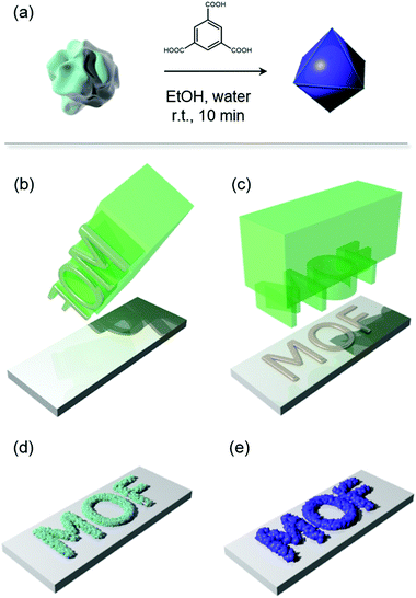
Herein, we report a novel strategy to position the HKUST-1 MOF on different supports through a two-step approach, namely, the positioning of the solvent insoluble Cu-based ceramic precursors on substrates, followed by their conversions into HKUST-1, as illustrated in Fig. 1. The solvent insoluble Cu-based precursors, which are ceramic materials according to modern definitions,21 have been obtained by reacting Cu(NO3)2·3H2O with ammonia solutions. The obtained nanopowder products were subsequently converted to HKUST-1 through the treatments with alcoholic solution containing H3BTC. This method has been successfully combined with a local deposition of a sol–gel solution to promote the adhesion between the ceramic nanopowder precursors and glass or plastic substrates. The ceramic patterns were converted into the corresponding HKUST-1 patterns. Remarkably, the pattern on the polymeric substrate could be bent, showing that MOF patterns can be applied on flexible substrates. According with the need for improved patterning protocols,15a the method proposed here offer a cheaper alternative to photolithography. Indeed, the process for the fabrication of the mold used in the contact printing process22 does not require proximity lithography equipment involved in the microfabrication of a thermally sensitive resist.13d Although the resolution in the present investigation is in the millimetre scale, use of established soft lithography protocols such as contact printing23 and dip-pen lithography24 can potentially increase the resolution up to a few microns.
Experimental
Materials
Ethanol (EtOH), copper(II) nitrate trihydrate (Cu(NO3)2·3H2O) and 1,3,5-benzenetricarboxylic acid (H3BTC) were purchased from Acros Organics. 3-Aminopropyltrimethoxysilane (APTMS) was obtained from Aldrich. 30% aq. ammonia was purchased from Chem-Supply. (3-Glycidoxypropyl)trimethoxysilane (GPTMS) was obtained from Dow Corning. HCl solution (1 M) was purchased from Scharla. A polymer (polyethylene terephthalate; PET) film with thickness of 0.1 mm was bought from Nobo. All materials were used as received without purification.Materials preparation
The insoluble ceramic Cu-based precursors were prepared as follows: 0.5–4 ml of mixed solutions of NH3 aq. (5 ml) and EtOH (25 ml) were added to EtOH (30 ml) containing 0.6 g of Cu(NO3)2·3H2O. The mixed solution was stirred for 24 h at room temperature. The precipitate was washed with water and collected by centrifugation. The collected powders were dried under vacuum at room temperature. The prepared samples are denoted as Cu-based precursors_X, where X = 0.5, 1, 2, 3 and 4 ml (amount of mixed solution of NH3 and EtOH added).HKUST-1 was prepared from the solvent insoluble Cu-based precursors as follows: 97 mg of Cu-based precursors_X was added to the mixed solution of 5 ml of EtOH and 2 ml of water containing 106 mg of H3BTC as an organic linker. The mixture was stirred for 10 min at room temperature. The deep turquoise-coloured powder was washed with water and EtOH, and then collected via centrifugation. The collected samples were dried under vacuum. The prepared samples are denoted as HKUST-1_X, where X = 0.5, 1, 2, 3 and 4 ml. For comparison, HKUST-1 was also prepared from Cu(NO3)2·3H2O by using the previously reported method.25 The prepared sample is denoted as HKUST-1_ref.
Positioning of HKUST-1 was performed via the following procedure: a sol–gel solution was prepared by mixing GPTMS (3 ml) and APTMS (3 ml) under stirring at room temperature, followed by adding 1 M HCl solution (0.1 ml) and stirring for 1 h at room temperature. The sol–gel solution was used as a viscous medium to bind the sprinkled Cu-based precursors_2 to substrates. The patterns were obtained using stamps to transfer the sol–gel solution onto selected locations. Subsequently, the MOF precursor was sprinkled on top of the patterned sol–gel solution. The system was aged for 5 minutes at room temperature to dry the sol–gel solution. For conversion to HKUST-1, the substrate was immersed into the mixed solution of 5 ml of EtOH and 2 ml of water containing 106 mg of H3BTC at room temperature. After 10 min, the substrate was removed from the solution and washed with EtOH, then dried in air.
General methods
The surface morphologies of samples were observed using a field emission scanning electron microscopy (FE-SEM; Merlin; Carl Zeiss Germany) with a thin Iridium film coating. X-ray powder diffraction (XRD) patterns were collected using a PANalytical X'Pert Pro diffractometer employing Co Kα radiation (λ = 0.179 nm). Nitrogen adsorption–desorption isotherms were collected using a BEL-SORP mini (BEL Japan, Inc.) at 77 K. Fourier transform infrared spectroscopy (FT-IR: ALPHA FT-IR spectrometer, Bruker Optik GmbH) was employed in the ATR configuration. Small-angle X-ray scattering (SAXS) and wide-angle X-ray scattering (WAXS) were performed at the Australian Synchrotron. A capillary with a 1.5 mm diameter was used for the in situ characterization by SAXS and WAXS. Once filled with the solution, the capillary was illuminated by a high-intensity X-ray beam at the beamline, and the scattered radiation was registered by the detector (Pilatus 1 M). An on-axis video camera allowed for parallax free sample viewing and alignment at all times before and during exposure, enabling precise and rapid sample alignment.Results and discussion
The solvent insoluble Cu-based precursors were prepared from Cu(NO3)2·3H2O by the ammonia treatment with different concentrations. Their SEM images are displayed in Fig. 2a–e. The particle size increased with the amount of ammonia added, and plate-like structures were seen at higher ammonia concentrations. Subsequently, the conversion of the insoluble Cu-based precursors was carried out by adding an alcoholic solution containing H3BTC. After about 10 seconds of reaction time, the colour of the precursor materials rapidly changed to deep turquoise, visibly indicating the formation of HKUST-1. Significant changes in morphology from the solvent insoluble Cu-based precursors to the octahedral crystals of HKUST-1 were observed, as shown in Fig. 2a′–e′. It should be noted that the particle size of HKUST-1 decreased with increasing amount of ammonia added for the preparations of the Cu-based precursors.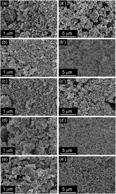 | ||
| Fig. 2 SEM images of the solvent insoluble Cu-based precursors (Cu-based precursors_X, (a–e) and corresponding HKUST-1_X (a′–e′). (a) X = 0.5, (b) X = 1, (c) X = 2, (d) X = 3, (e) X = 4. | ||
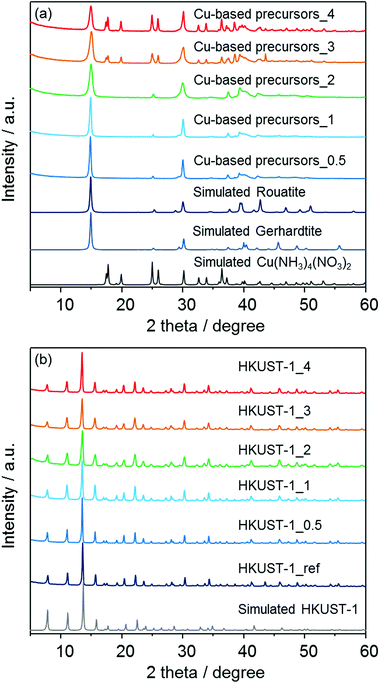
In order to confirm the formation of HKUST-1 structures, powder X-ray diffraction (XRD) measurements were carried out. As shown in Fig. 3a, the insoluble Cu-based precursors were found to include the crystalline Cu2(OH)3NO326 and Cu(NH3)4(NO3)2 phases.27 The data were analyzed using the Rietveld method,28 and the approximate phase fractions were calculated using the method of Hill and Howard.29 The peaks in the diffraction patterns collected from the three samples prepared with less than 3 ml of ammonia solution indicate that the samples contain a large proportion of the Cu2(OH)3NO3 phase. However, Cu2(OH)3NO3 has two polymorphs, the monoclinic rouaite phase,26a and the orthorhombic gerhardite phase26b with very similar diffraction patterns (see Fig. S1 in the ESI†). The difference between this phases relates to the packing of the NO3− ions between the Cu layers. Analysis of the diffraction data indicates both phases are present in the samples, however, discrepancies between the observed and calculated patterns suggest there may be some disorder between the layers of the Cu2(OH)3NO3 phase(s). The samples prepared with 3 and 4 ml of ammonia solution were found to also contain the crystalline Cu(NH3)4(NO3)2 phase.27 The Rietveld analysis indicates that the concentration of this phase increases with increasing ammonia solution. For example, excluding any amorphous component, the proportion of the Cu(NH3)4(NO3)2 phase to the Cu2(OH)3NO3 phase(s) increased from ∼27 wt% to ∼53 wt% from 3 ml to 4 ml of ammonia solution respectively (Fig. S2 in the ESI†). However, the accuracy of these measurements is limited by discrepancies between the observed and calculated relative peak intensities of the Cu2(OH)3NO3 phase. An EDX investigation revealed the presence of carbon (6–8%) confirming the presence of residual solvent (ethanol), which may disrupt the crystal structure of the Cu2(OH)3NO3 phase. Previous studies have shown that layered metal hydroxy nitrates can be sensitive to the presence and intercalation of organic molecules.30 It was also found that the observed diffraction patterns after the conversion to MOFs (Fig. 3b) are in good agreement with the previously-reported diffraction pattern of a HKUST-1-type structure31 as well as the pattern of HKUST-1_ref which was synthesized following the aqueous room temperature protocol proposed by Bradshaw et al.25 No diffraction peaks corresponding to residual precursors or the bulk copper oxides were observed for the patterns of converted HKUST-1_X.
FT-IR measurements were also performed to characterize both the insoluble Cu-based precursors and the corresponding HKUST-1. The spectra are displayed in Fig. 4. In the spectra for Cu-based precursors_X, the wide band attributed to O–H stretching modes appeared in the region of 3550–3200 cm−1.32a The mode at around 3340 cm−1 for Cu-based precursors_3 and 4 is attributed to the N–H stretching vibration, suggesting the presence of residual NH3.32b The absorption bands at around 877, 1044, 1240, 1296, 1333 and 1416 cm−1 can be assigned to vibrational modes of nitrate (NO3−) ions having an interaction with copper hydroxide layers.32c,d Moreover, the bands at 1640 and 820 cm−1 for Cu-based precursors_3 and 4 are attributed to the N–H bending mode.32b The remaining bands at 670 and 772 cm−1 are assigned to the Cu–OH stretching mode.32e After treatments with an alcoholic solution containing H3BTC, the absorption bands attributed to O–H stretching modes in the region of 3550–3200 cm−1 significantly decreased for all HKUST-1_X samples. New modes were observed and are assigned to the organic molecules used as ligands in the HKUST-1_X frameworks (BTC); 729, 760, 940 cm−1: C–CO2 stretching, 1114 cm−1: C–O stretching, 1373, 1449, 1645 cm−1: COO–Cu2 stretching.33 These results confirmed the conversions of the solvent insoluble Cu-based precursors to HKUST-1. The absorption bands coming from nitrate ions are still observable for all HKUST-1_X materials.
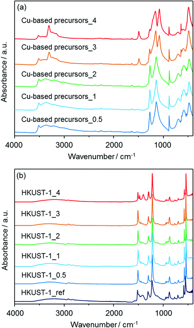 | ||
| Fig. 4 FT-IR spectra of (a) the solvent insoluble Cu-based precursors (Cu-based precursors_X) and (b) corresponding HKUST-1_X with HKUST-1_ref. | ||
N2 adsorption isotherms are shown in Fig. 5. Using the BET (Brunauer–Emmett–Teller) method, the specific surface areas of the Cu-based precursors_X (X = 0.5, 1, 2, 3 and 4) were measured (26, 23, 16, 11 and 6 m2 g−1 respectively), showing that the feedstock ceramic materials have a low porosity. After conversion into the MOF, type I isotherms were measured for all of the prepared materials, indicating the microporosity of the samples. The specific surface areas of HKUST-1_X (X = 0.5, 1, 2, 3 and 4) were determined to be 1021, 1019, 998, 965, and 966 m2 g−1, respectively. HKUST-1_ref was also found to have the surface area of 1236 m2 g−1. With the room temperature conversion proposed here, we found that the surface areas are between 17% (HKUST-1_0.5) to 22% (HKUST-1_3 and 4) lower than HKUST-1_ref. This result suggests the residual precursor species still exist in the framework, which is consistent with the results obtained by FT-IR measurements. This conclusion is supported by the previous studies converting other Cu-based ceramics into HKUST-1.19,20 In summary, the investigation performed here (XRD, FT-IR and N2 adsorption measurements) indicates the formation of HKUST-1 from the solvent insoluble Cu-based precursors.
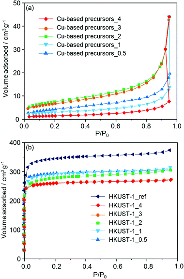 | ||
| Fig. 5 N2 adsorption isotherms of (a) the solvent insoluble Cu-based precursors (Cu-based precursors_X) and (b) corresponding HKUST-1_X with HKUST-1_ref measured at 77 K. | ||
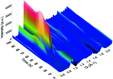
In situ SAXS/WAXS measurements were conducted at the Australian Synchrotron to gain an insight into the kinetics of HKUST-1 growth from the solvent insoluble Cu-based precursors. For the measurements, the Cu-based precursors were placed in a capillary with the mixed solution of EtOH and water, followed by the controlled addition of the alcoholic solution containing the H3BTC linker using a syringe. Once filled with the solution, the capillary was illuminated by a high-intensity X-ray beam, and the scattered radiation was collected by the two 2D detectors. The obtained 2D scattering patterns have been background-subtracted, radially integrated and plotted as a function of the reaction time. As an example, the conversion from Cu-based precursors_2 into HKUST-1_2 is shown in Fig. 6. The peaks attributed to the HKUST-1 structure appeared just after the ligand was injected (within 5 seconds). Within 30 seconds of the ligand injection, plateaus were found in the peaks corresponding to the HKUST-1 structure including two intense peaks which appeared at Q = 0.67 and 0.82 Å−1. These peaks are attributed to the (022) and (222) planes of the HKUST-1 framework, respectively. This result indicates that the conversion process was almost completed within 30 seconds of the reaction time. Similar trends were observed for all of the samples, with the reaction occurring within ca. 30 seconds. However, fluctuations in the intensity of the diffraction peaks were observed due to MOF crystals passing in and out of the volume illuminated by the X-ray beam in the process of settling to the bottom of the capillary, which made accurate quantification of the phase fractions difficult.
HKUST-1 was recently used as a functional material for sensing,34a catalysis,34b decontamination34c and electronics.34d Here we propose a protocol that can position HKUST-1 on substrates for their potential use in practical device fabrication. The protocol can be described as a two-step approach. First, the solvent insoluble Cu-based precursors were positioned on a glass slide and fixed on it using a sol–gel solution based on APTMS and GPTMS (Fig. 7a). Then, the substrate was immersed into the mixed solution of EtOH and water containing H3BTC (10 min, 25 °C) to convert precursor materials to HKUST-1 (Fig. 7b). SEM measurements confirmed the successful formation of the octahedral crystal morphology of HKUST-1 on the glass slide as found for the free nanopowder form. A highly advantageous aspect of the approach proposed here is the variety of patterning procedures available for the sol–gel technology.35 Although synthesis of MOF thin films have been of great interest in recent years, there are only several reports describing the fabrication of MOF thin films on flexible substrates, such as porous polymers and paper fibers.36 Positioning of MOFs on flexible substrates would offer further opportunities for practical applications due to their light weight, flexibility, low cost, and ease of design over conventional substrates.37 To demonstrate this, a bendable polyethylene terephthalate (PET) film was employed as a substrate using the same method developed in this study, as shown in Fig. 8. Positioning of HKUST-1 was successfully demonstrated through the two-step approach. It was also confirmed that the prepared film could be easily bent without changes in the positioned MOF, as shown in Fig. 8d. A previous study proposed an interesting technique (ink-jet printing) for the positioning HKUST-1 on a number of substrates, including flexible plastic sheets.36e However, the protocol proposed here does not require heating steps or the use of hazardous solvents (e.g. DMSO) in the process. In addition, this environmentally friendly approach offers easy access to positioned MOFs for the exploration of MOF properties in miniaturized devices and the exploitation of the functional properties for industrial application.
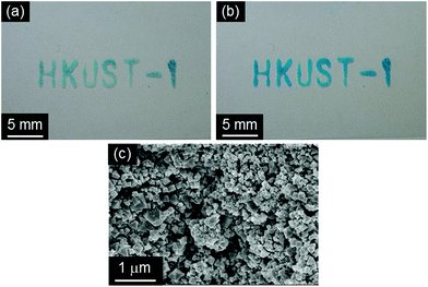 | ||
| Fig. 7 Photographs of (a) the positioned solvent insoluble Cu-based precursors (Cu-based precursors_2 and (b) HKUST-1_2 and (c) SEM image of HKUST-1_2 on a slide glass substrate. | ||
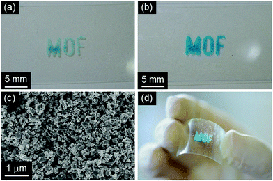 | ||
| Fig. 8 Photographs of (a) the positioned solvent insoluble Cu-based precursors (Cu-based precursors_2 and (b, d) HKUST-1_2 and (c) SEM image of HKUST-1_2 on a PET substrate. | ||
Conclusions
We have presented the conversion of solvent insoluble Cu-based precursors into HKUST-1 through a simple and quick acid–base reaction at room temperature. The technique has been successfully adopted for use in the positioning of MOFs on flat substrates. To demonstrate the broad versatility and applicability of this method, positioning was also performed on a flexible polymer substrate. The fabricated thin film was found to be easily bendable without change in the positioned MOF crystals. This approach offers significant advantages including the stability over time of the Cu-based ceramic nanopowder used as a precursor, an environmentally friendly protocol for the conversion from ceramic into HKUST-1 and the exploitation of established technologies for HKUST-1 film and pattern fabrication.Acknowledgements
The present work is supported by “ACCEL Project” from the Japan Science and Technology Agency, by Grants-in-Aid for Scientific Research from the Ministry of Education, Culture, Sports, Science and Technology of Japan (No. 25410241) and Strategic Young Researcher Overseas Visits Program for Accelerating Brain Circulation. Part of this research was undertaken on the SAXS beamline at the Australian Synchrotron, Victoria, Australia with the support of Dr Nigel Kirby and Dr Adrian Hawley. P.F. acknowledges the Australian Research Council (ARC, DECRA Grant DE120102451), the AMTCP scheme, and the OCE science team for the Julius Award. T. T. and K. O. thank the JSPS Research Fellowships for Young Scientists.Notes and references
- (a) S. Furukawa, J. Reboul, S. Diring, K. Sumida and S. Kitagawa, Chem. Soc. Rev., 2014, 43, 5700 RSC; (b) G. Férey, Chem. Soc. Rev., 2008, 37, 191 RSC; (c) H. Furukawa, K. E. Cordova, M. O'Keeffe and O. M. Yaghi, Science, 2013, 341, 1230444 CrossRef PubMed; (d) C. M. Doherty, D. Buso, A. J. Hill, S. Furukawa, S. Kitagawa and P. Falcaro, Acc. Chem. Res., 2014, 47, 396 CrossRef CAS PubMed.
- (a) N. L. Rosi, J. Eckert, M. Eddaoudi, D. T. Vodak, J. Kim, M. O'Keeffe and O. M. Yaghi, Science, 2003, 300, 1127 CrossRef CAS PubMed; (b) K. Sumida, D. L. Rogow, J. A. Mason, T. M. McDonald, E. D. Bloch, Z. R. Herm, T.-H. Bae and J. R. Long, Chem. Rev., 2012, 112, 724 CrossRef CAS PubMed; (c) Q. L. Zhu and Q. Xu, Chem. Soc. Rev., 2014, 43, 5468 RSC.
- (a) J. Lee, O. K. Farha, J. Roberts, K. A. Scheidt, S. T. Nguyen and J. T. Hupp, Chem. Soc. Rev., 2009, 38, 1450 RSC; (b) A. Corma, H. Garcia and F. X. Llabrés i Xamena, Chem. Rev., 2010, 110, 4606 CrossRef CAS PubMed; (c) A. Aijaz, A. Karkamkar, Y. J. Choi, N. Tsumori, E. Ronnebro, T. Autrey, H. Shioyama and Q. Xu, J. Am. Chem. Soc., 2012, 134, 13926 CrossRef CAS PubMed; (d) J. Liu, L. Chen, H. Cui, J. Zhang, L. Zhang and C. Y. Su, Chem. Soc. Rev., 2014, 43, 6011 RSC; (e) J. D. Evans, C. J. Sumby and C. J. Doonan, Chem. Soc. Rev., 2014, 43, 5933 RSC; (f) S. Ou and C. D. Wu, Inorg. Chem. Front., 2014, 1, 721 RSC.
- (a) J. R. Li, R. J. Kuppler and H. C. Zhou, Chem. Soc. Rev., 2009, 38, 1477 RSC; (b) Y. S. Li, F. Y. Liang, H. Bux, A. Feldhoff, W. S. Yang and J. Caro, Angew. Chem., Int. Ed., 2010, 49, 548 CrossRef CAS PubMed; (c) Z. Hu, B. J. Deibert and J. Li, Chem. Soc. Rev., 2014, 43, 5815 RSC.
- (a) O. Shekhah, J. Liu, R. A. Fischer and C. Woll, Chem. Soc. Rev., 2011, 40, 1081 RSC; (b) J. Gascon, F. Kapteijn, B. Zornoza, V. Sebastian, C. Casado and J. Coronas, Chem. Mater., 2012, 24, 2829 CrossRef CAS; (c) R. Matsuda, R. Kitaura, S. Kitagawa, Y. Kubota, R. V. Belosludov, T. C. Kobayashi, H. Sakamoto, T. Chiba, M. Takata, Y. Kawazoe and Y. Mita, Nature, 2005, 436, 238 CrossRef CAS PubMed; (d) S. Qiu, M. Xue and G. Zhu, Chem. Soc. Rev., 2014, 43, 6116 RSC.
- (a) V. Stavila, A. A. Talind and M. D. Allendorf, Chem. Soc. Rev., 2014, 43, 5994 RSC; (b) P. Ramaswamy, N. E. Wang and G. K. H. Shimizu, Chem. Soc. Rev., 2014, 43, 5913 CAS; (c) L. Dun, T. Miyakai, S. Seki and M. Dincă, J. Am. Chem. Soc., 2013, 135, 8185 CrossRef PubMed.
- (a) B. Van de Voorde, B. Bueken, J. Denayer and D. De Vos, Chem. Soc. Rev., 2014, 43, 5766 RSC; (b) R. Ricco, L. Malfatti, M. Takahashi, A. J. Hill and P. Falcaro, J. Mater. Chem. A, 2013, 1, 13033 RSC.
- (a) P. Horcajada, R. Gref, T. Baati, P. K. Allan, G. Maurin, P. Couvreur, G. Férey, R. E. Morris and C. Serre, Chem. Rev., 2012, 112, 1232 CrossRef CAS PubMed; (b) S. Keskin and S. Kızılel, Ind. Eng. Chem. Res., 2011, 50, 1799 CrossRef CAS.
- (a) P. Falcaro, D. Buso, A. J. Hill and C. Doherty, Adv. Mater., 2012, 24, 3145 CrossRef CAS; (b) M. Tu, S. Wannapaiboon and R. Fischer, Inorg. Chem. Front., 2014, 1, 442 RSC.
- P. Falcaro, R. Ricco, C. M. Doherty, K. Liang, A. J. Hill and M. J. Styles, Chem. Soc. Rev., 2014, 43, 5513 RSC.
- (a) R. Ameloot, E. Gobechiya, H. Uji-i, J. A. Martens, J. Hofkens, L. Alaerts, B. F. Sels and D. E. De Vos, Adv. Mater., 2010, 22, 2685 CrossRef CAS PubMed.
- (a) H. K. Arslan, O. Shekhah, J. Wohlgemuth, M. Franzreb, R. A. Fischer and C. Woll, Adv. Funct. Mater., 2011, 21, 4228 CrossRef CAS; (b) P. Falcaro, A. J. Hill, K. M. Nairn, J. Jasieniak, J. I. Mardel, T. J. Bastow, S. C. Mayo, M. Gimona, D. Gomez, H. J. Whitfield, R. Ricco, A. Patelli, B. Marmiroli, H. Amenitsch, T. Colson, L. Villanova and D. Buso, Nat. Commun., 2011, 2, 237 CrossRef PubMed.
- (a) G. Lu, O. K. Farha, W. Zhang, F. Huo and J. T. Hupp, Adv. Mater., 2012, 24, 3970 CrossRef CAS PubMed; (b) C. Dimitrakakis, B. Marmiroli, H. Amenitsch, L. Malfatti, P. Innocenzi, G. Grenci, L. Vaccari, A. J. Hill, B. P. Ladewig, M. R. Hill and P. Falcaro, Chem. Commun., 2012, 48, 7483 RSC; (c) B. K. Keitz, C. J. Yu, J. R. Long and R. Ameloot, Angew. Chem., Int. Ed., 2014, 53, 5561 CrossRef CAS PubMed; (d) C. M. Doherty, G. Grenci, R. Ricco, J. I. Mardel, J. Reboul, S. Furukawa, S. Kitagawa, A. J. Hill and P. Falcaro, Adv. Mater., 2013, 34, 4701 CrossRef PubMed.
- (a) X. Zou, G. Zhu, I. J. Hewitt, F. Sun and S. Qiu, Dalton Trans., 2009, 3009 RSC; (b) J. Reboul, S. Furukawa, N. Horike, M. Tsotsalas, K. Hirai, H. Uehara, M. Kondo, N. Louvain, O. Sakata and S. Kitagawa, Nat. Mater., 2012, 11, 717 CrossRef CAS PubMed; (c) G. Majano, O. Ingold, M. Yulikov, G. Jeschke and J. Pérez-Ramírez, CrystEngComm, 2013, 15, 9885 RSC; (d) I. Stassen, N. Campagnol, J. Fransaer, P. Vereecken, D. D. Vos and R. Ameloot, CrystEngComm, 2013, 15, 9308 RSC.
- (a) P. Falcaro, L. Malfatti, L. Vaccari, H. Amenitsch, B. Marmiroli, G. Grenci and P. Innocenzi, Adv. Mater., 2009, 21, 4932 CrossRef CAS PubMed; (b) E. Zanchetta, G. D. Giustina, G. Grenci, A. Pozzato, M. Tormen and G. Brusatin, Adv. Mater., 2013, 25, 6261 CrossRef CAS PubMed.
- (a) U. Schulz, B. Saruhan, K. Fritscher and C. Leyens, Int. J. Appl. Ceram. Technol., 2004, 1, 302 CrossRef CAS PubMed; (b) D. A. Streitwieser, N. Popovska, H. Gerhard and G. Emig, J. Eur. Ceram. Soc., 2005, 25, 817 CrossRef CAS PubMed.
- (a) M. Nanu, J. Schoonman and A. Goossens, Nano Lett., 2005, 5, 1716 CrossRef CAS PubMed; (b) G. L. Messing, S. C. Zhang and G. V. Jayanthi, J. Am. Ceram. Soc., 1993, 76, 2707 CrossRef CAS PubMed.
- (a) A. R. Studart, U. T. Gonzenbach, E. Tervoort and L. J. Gauckler, J. Am. Ceram. Soc., 2006, 89, 1771 CrossRef CAS PubMed; (b) L. Besra and M. Liu, Prog. Mater. Sci., 2007, 52, 1 CrossRef CAS PubMed.
- G. Majano and J. Pérez-Ramírez, Adv. Mater., 2013, 25, 1052 CrossRef CAS PubMed.
- K. Okada, R. Ricco, Y. Tokudome, M. J. Styles, A. J. Hill, M. Takahashi and P. Falcaro, Adv. Funct. Mater., 2014, 24, 1969 CrossRef CAS.
- D. W. Richerson, Modern ceramic engineering: properties, processing, and use in design, CRC Taylor & Francis, Boca Raton, FL, 3rd edn, 2006 Search PubMed.
- E. Zanchetta, L. Malfatti, R. Ricco, M. J. Styles, F. Lisi, C. J. Coghlan, C. J. Doonan, A. J. Hill, G. Brusatin and P. Falcaro, Chem. Mater., 2015, 27, 690 CrossRef CAS.
- D. Qin, Y. N. Xia and G. M. Whitesides, Nat. Protoc., 2010, 5, 491 CrossRef CAS PubMed.
- (a) R. D. Piner, J. Zhu, F. Xu, S. H. Hong and C. A. Mirkin, Science, 1999, 283, 661 CrossRef CAS; (b) D. S. Ginger, H. Zhang and C. A. Mirkin, Angew. Chem., Int. Ed., 2004, 43, 30 CrossRef PubMed.
- J. Huo, M. Brightwell, S. Hankari, A. Garai and D. Bradshaw, J. Mater. Chem. A, 2013, 1, 15220 CAS.
- (a) H. Effenberger, Z. Kristallogr., 1983, 165, 127 CrossRef CAS PubMed; (b) B. Bovio and S. Locchi, J. Crystallogr. Spectrosc. Res., 1982, 12, 507 CrossRef CAS.
- B. Morosin, Acta Crystallogr., Sect. B: Struct. Crystallogr. Cryst. Chem., 1976, 32, 1237 CrossRef.
- H. M. Rietveld, J. Appl. Crystallogr., 1969, 2, 65 CrossRef CAS.
- R. J. Hill and C. J. Howard, J. Appl. Crystallogr., 1987, 20, 467 CrossRef CAS.
- J. T. Rajamathi, A. Arulraj, N. Ravishankar, J. Arulraj and M. Rajamathi, Langmuir, 2008, 24, 11164 CrossRef CAS PubMed.
- S. S.-Y. Chui, S. M.-F. Lo, J. P. H. Charmant, A. G. Orpen and I. D. Williams, Science, 1999, 283, 1148 CrossRef CAS.
- (a) I. Y. Park, K. Kuroda and C. Kato, Solid State Ionics, 1990, 42, 197 CrossRef CAS; (b) G. Socrates, Infrared and Raman characteristic group frequencies: tables and charts, John Wiley & Sons, 3rd edn, 2004 Search PubMed; (c) K. Nakamoto, Infrared and Raman Spectra of Inorganic and Coordination Compounds, John Wiley & Sons, 4th edn, 1986 Search PubMed; (d) J. M. Aguirre, A. Gutiérrez and O. Giraldo, J. Braz. Chem. Soc., 2011, 22, 546 CrossRef CAS PubMed; (e) A. Yin, X. Guo, W. L. Dai and K. Fan, J. Phys. Chem. C, 2009, 113, 11003 CrossRef CAS.
- (a) J. L. C. Rowsell and O. M. Yaghi, J. Am. Chem. Soc., 2006, 128, 1304 CrossRef CAS PubMed; (b) S. Loera-Serna, L. López-Núñez, J. Flores, R. López-Simeon and H. I. Beltrán, RSC Adv., 2013, 3, 10962 RSC; (c) S. Loera-Serna, M. A. Oliver-Tolentino, M. de Lourdes López-Núñez, A. Santana-Cruz, A. Guzmán-Vargas, R. Cabrera-Sierra, H. I. Beltrán and J. Flores, J. Alloys Compd., 2012, 540, 113 CrossRef CAS PubMed.
- (a) H. Yamagiwa, S. Sato, T. Fukawa, T. Ikehara, R. Maeda, T. Mihara and M. Kimura, Sci. Rep., 2014, 4, 6247 CrossRef CAS PubMed; (b) M. Polozij, M. Rubes, J. Cejka and P. Nachtigall, ChemCatChem, 2014, 6, 2821 CrossRef CAS; (c) Z. Wang, J. Wang, M. Li, K. Sun and C. Liu, Sci. Rep., 2014, 4, 5939 CAS; (d) A. A. Talin, A. Centrone, A. C. Ford, M. E. Foster, V. Stavila, P. Haney, R. A. Kinney, V. Szalai, F. E. Gabaly, H. P. Yoon, F. Léonard and M. D. Allendorf, Science, 2014, 343, 66 CrossRef CAS PubMed.
- J. Blum and D. Avnir, in Handbook of sol-gel science and technology, ed. S. Sakka, Kluwer Scientific Publishers, 2005, vol. 3 Search PubMed.
- (a) Y. Zhang, I. H. Musselman, J. P. Ferraris and K. J. Balkus, J. Membr. Sci., 2008, 313, 170 CrossRef CAS PubMed; (b) T. Ben, C. Lu, C. Pei, S. Xu and S. Qiu, Chem. – Eur. J., 2012, 18, 10250 CrossRef CAS PubMed; (c) R. Jin, Z. Bian, J. Li, M. Ding and L. Ga, Dalton Trans., 2013, 42, 3936 RSC; (d) J. Yao, D. Dong, D. Li, L. He, G. Xu and H. Wang, Chem. Commun., 2011, 47, 2559 RSC; (e) J. L. Zhuang, D. Ar, X.-J. Yu, J.-X. Liu and A. Terfort, Adv. Mater., 2013, 25, 4631 CrossRef CAS PubMed.
- (a) A. Hozumi, T. Kizuki, M. Inagaki and N. Shirahata, J. Vac. Sci. Technol., A, 2006, 4, 24 Search PubMed; (b) A. Yildirim, H. Budunoglu, M. Yaman, M. O. Guler and M. Bayindir, J. Mater. Chem., 2011, 21, 14830 RSC.
Footnote |
| † Electronic supplementary information (ESI) available. See DOI: 10.1039/c4qi00215f |
| This journal is © the Partner Organisations 2015 |

