 Open Access Article
Creative Commons Attribution 3.0 Unported Licence
Ambient solid-state triplet–triplet annihilation upconversion in ureasil organic–inorganic hybrid hosts†
Abigail R.
Collins
 ,
Bolong
Zhang‡
 ,
Michael J.
Bennison
 and
Rachel C.
Evans
 *
*
Department of Materials Science and Metallurgy, University of Cambridge, 27 Charles Babbage Road, Cambridge, CB3 0FS, UK. E-mail: rce26@cam.ac.uk
First published on 15th April 2024
Abstract
Triplet–triplet-annihilation upconversion (TTA-UC) has attracted significant attention as an approach to harvest low energy solar photons that cannot be captured by conventional photovoltaic devices. However, device integration requires the design of solid-state TTA-UC materials that combine high upconversion efficiency with long term stability. Herein, we report an efficient solid-state TTA-UC system based on organic–inorganic hybrid polymers known as ureasils as hosts for the archetypal sensitiser/emitter pair of palladium(II) octaethylporphyrin and diphenylanthracene. The role of the ureasil structure on the TTA-UC performance was probed by varying the branching and molecular weight of the organic precursor to tune the structural, mechanical, and thermal properties. Solid-state green-to-blue UC quantum yields of up to 1.86% were observed under ambient conditions. Notably, depending on the ureasil structure, UC emission could be retained for >70 days without any special treatment, including deoxygenation. Detailed analysis of the structure-function trends revealed that while a low glass transition temperature is required to promote TTA-UC molecular collisions, a higher inorganic content is the primary factor that determines the UC efficiency and stability, due to the inherent oxygen barrier provided by the silica nanodomains.
Introduction
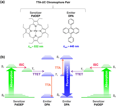
Triplet–triplet-annihilation upconversion (TTA-UC) is a photochemical process whereby two low energy photons are converted to a single higher energy photon,1,2 and has diverse applications in bioimaging,3,4 anti-counterfeiting,5 photocatalysis,6,7 sensing,8 and solar energy harvesting.9–11 As illustrated in Fig. 1, TTA-UC occurs between a chromophore pair, comprising a sensitiser with high intersystem crossing (ISC) efficiency, (e.g., palladium(II) octaethylporphyrin (PdOEP)) and an emitter, such as diphenylanthracene (DPA).12 Since TTA-UC requires rapid energy transfer between the sensitiser and emitter, the physical properties of the host medium are also closely linked to the efficiency, quantified by the upconversion quantum yield (ΦUC, which is capped at 50%).13,14 Although high efficiencies (ΦUC ∼30%) can be achieved in liquid media,15–17 due to rapid molecular collisions and the ease of degassing to prevent oxygen quenching, this has limited practical use. In contrast, a solid-state system will not evaporate or leak and can offer mechanical stability for device integration.It is typically challenging to achieve a high ΦUC in the solid-state,18,19 due to the potential problems of parasitic absorption, limited triplet-diffusion, and inhomogeneous chromophore distribution.20,21 To overcome these energy sinks, the ideal solid-state host must be transparent and allow good chromophore dissolution and mobility. In addition, it should provide barrier properties to reduce oxygen triplet quenching and a mechanical scaffold for practical integration. These traits are often contradictory and difficult to marry into one system.19 As such, a wide variety of materials and architectures have been investigated as solid-state UC hosts including gels,22–24 particles,25–28 metal–organic frameworks,29,30 micro or nanodroplet-containing polymers,31,32 and copolymers.33,34 Among these, polymer systems are particularly attractive due to their ease of processability and integration with thin film devices. Organic polymers with low glass transition temperature (Tg) such as polyurethanes have been demonstrated to facilitate molecular diffusion, but lack the mechanical stability and oxygen protection that inorganic systems provide.18,19,35 In high Tg polymers such as poly(methyl methacrylate),36,37 chromophores are immobilised within the rigid matrix,38–40 meaning the triplet–triplet energy transfer (TTET) rate relies entirely on homogenous blending to ensure triplet excitons transfer via an energy migration mechanism, leading to lower overall efficiencies.10,19,20
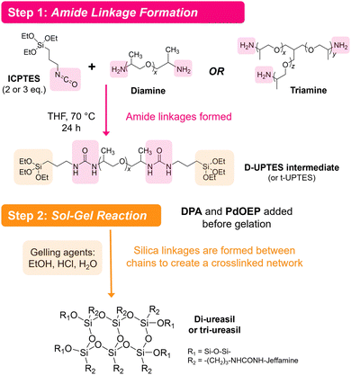
Organic–inorganic hybrid polymers may offer a solution to these limitations. However, to the best of our knowledge, hybrid polymers have not yet been deployed as TTA-UC hosts, despite offering highly favourable characteristics. For example, ORMOCERS® have been investigated extensively for use as food packaging materials due their excellent barrier abilities against oxygen, water vapor and other compounds.41–43 Moreover, with judicious selection of a low Tg organic precursor, it should be possible to design a hybrid polymer that provides a suitable environment to both solubilise embedded chromophores and facilitate molecular collisions. Herein, we explore this opportunity by demonstrating organic–inorganic hybrid ureasil polymers as chromophore hosts for solid-state TTA-UC for the first time. Ureasils consist of poly(oxyalkylene) chains covalently linked to a siliceous network via urea bridges (Fig. 2).44,45 The structure and organic-to-inorganic ratio can be easily tuned by altering the branching or molecular weight of the polymer backbone to form monoliths of varying Tg and flexibility.46–48 Ureasils have been used as waveguides for luminescent solar concentrators,47–49 electrochromic windows,50 and optical communications46,51 due to their ability to encapsulate organic and inorganic dopants. Moreover, both non-specific intermolecular forces such as hydrogen bonding, ionic or π–π interactions,52 or specific covalent grafting have been demonstrated as successful strategies to both solubilise and localise organic chromophores.53
Using the benchmark DPA/PdOEP chromophore pair, we examine the effect the chain length and branching of the organic polymer backbone on the TTA-UC activity in ureasil hosts. While efficient green-to-blue upconversion was observed in all ureasils, the champion host DU(2000) exhibited a maximum ΦUC of 1.86 ± 0.05 at 1 W cm−2, which is comparable to other similar solid-state systems.19,54 Crucially, this efficiency is observed under ambient conditions (i.e., no oxygen removal) and measurable UC persists over 76 days. Moreover, both the UC efficiency and stability can be directly correlated with the organic-to-inorganic ratio in the ureasil host. Through detailed structural analysis, we tentatively link this to faster molecular diffusion for lower Tg systems, and improved oxygen resistance for those with higher silica content.
Results and discussion
Design of ureasil hosts
Ureasils are synthesised using a previously reported two-step process,46 in which a poly(oxyalkylene) is first reacted with the silica precursor isocyanatopropyltriethoxysilane (ICPTES) to form urea bridges, before the system is cross-linked at the silicate terminus using sol–gel chemistry (Fig. 2). By varying the length and branching of the poly(oxyalkylene), the ratio of organic to inorganic content in the final ureasil can be tuned. This ratio affects properties such as the Tg and flexibility of the host. Four poly(oxyalkylene) precursors were investigated and the resulting ureasils are given the following nomenclature according to literature convention: DU(2000), DU(4000), tU(3000), and tU(5000). The D or t terms refer to the branching, being di- or tri-branched respectively, and the number in brackets is the molecular weight (MW) of the poly(oxyalkylene).Prior to gelation, ureasils were doped with the sensitiser-emitter pair: PdOEP (0.1 mM with respect to (w.r.t.) the dry monolith) and DPA (10 mM w.r.t. the dry monolith). These ratios were selected based on the UC performance of a set of test samples of tU(3000) loaded with different concentrations and ratios of DPA and PdOEP (see Section S3, Table S2 in ESI†). We note that while high, these sensitiser/emitter concentrations are in line with typical concentrations used in similar solid-state TTA-UC systems.31,35 For elevated emitter concentrations, competing relaxation pathways such as self-annihilation and/or reabsorption can occur.21,55 As some evidence of these processes was observed at higher (20 mM) emitter concentrations (reduced UC lifetime, decreased UC emission counts, Tables S2 and S3, ESI†), we selected DPA (10 mM) as the upper concentration limit. Reference samples containing just PdOEP or DPA (at equivalent loadings) or no lumophore at all were also prepared for comparison. Once formed, the gels were air-dried to evaporate residual solvent, yielding free-standing monoliths. We note that tri-branched ureasils shrink in size (relative to the initial solution volume) more than di-branched, as do lower molecular weight variants. All ureasils were characterised by powder X-ray diffraction (PXRD) and Fourier transform infrared (FTIR) spectroscopy and display structural features characteristic of ureasils. Full details of the synthetic methods and structural characterisation can be found in the ESI† (ESI,† see Sections S1.2 and S6). It is important to note that all samples were prepared under ambient conditions and not degassed at any point.
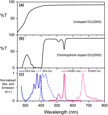
The parent ureasils show high optical transmittance (>90%) in the visible range, with a cut-off around 250–300 nm (see Fig. 3a for DU(2000), and Fig. S2 for all other ureasils, ESI†). This cut-off can provide UV-B protection to reduce chromophore photobleaching.56 When doped, the ureasils still show high transmittance >600 nm, but as expected absorb strongly in the spectral regions of the chromophores (∼490–560 nm for PdOEP, 300–420 nm for DPA, Fig. 3b). The absorption and emission spectra of DPA (λex = 375 nm) and PdOEP (λex = 532 nm) in THF solution are shown in Fig. 3c for reference. Solid-state emission measurements on doped ureasils under selective excitation of either the sensitiser or emitter further confirmed successful integration into the ureasil host (Fig. S4, ESI†).
TTA-UC activity in ureasils
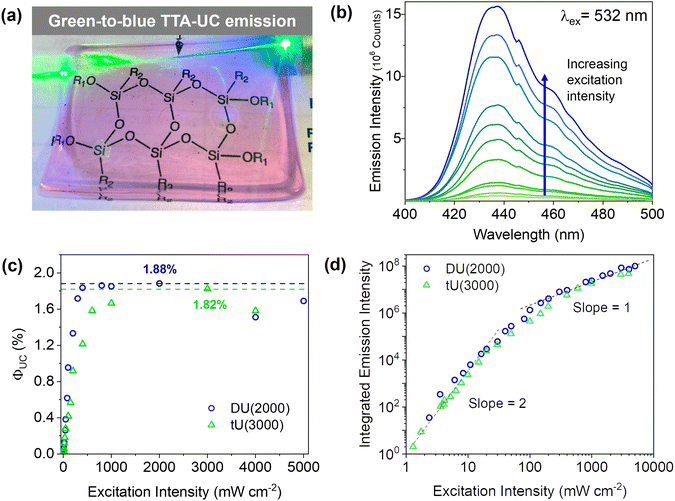
Doped ureasils show green-to-blue upconversion in ambient conditions when irradiated with a green laser pointer (see Fig. 4a and Fig. S4, Video S1, ESI†). No UC emission is observed in the absence of PdOEP, which supports the sensitised mechanism. These results were confirmed by steady-state photoluminescence spectroscopy (Fig. 4b, and Fig. S5, ESI†). Upon excitation at 532 nm (in the PdOEP absorption band), a broad emission between 400–500 nm is observed, which increases with excitation intensity. We note subtle differences in structure of the UC emission band compared to direct excitation of DPA (at 375 nm in dilute solution, see Fig. 3c), namely the absence of the first vibronic band at 408 nm and the red-shift of the second peak maximum to 440 nm. This behaviour is typical of strong self-absorption due to the high emitter concentration. The photoluminescence quantum yield (ΦPL) upon direct excitation at 375 nm is >95% for all DPA-ureasils (Table S4, ESI†), which is comparable to the near-unity ΦPL of DPA in solution (95% in ethanol).57,58 This demonstrates that the ureasil does not affect the performance of DPA as an emitter. In presence of PdOEP, the ΦPL (λex = 375 nm) decreases, but remains high (78–87%, Table 2). This may be due in part to parasitic absorption from the Soret band of the sensitiser (which cannot be isolated from the DPA absorption in the ΦPL measurement), along with the presence of new non-radiative relaxation pathways. In both cases, it is noted that the ΦPL is higher for DU(2000) and tU(3000) than their higher MW counterparts, and higher in tri-branched than di-branched ureasils. While ureasils are known to emit weakly between 390–600 nm upon excitation at 375 nm (see Fig. S6, ESI†)47,59 the ΦPL of undoped ureasils (2–7%, with the exception of DU(2000), Table S4, ESI†) is significantly lower than that of DPA. More importantly, no detectable ureasil emission is observed upon excitation at 532 nm, meaning the ureasil host should not offer competing photophysical pathways to the TTA-UC process.To quantitatively compare the TTA-UC activity in different ureasils, the upconversion quantum yield was measured (see Section S1.5, ESI†). Since the process requires two lower energy photons to emit one photon of higher energy, the maximum ΦUC cannot exceed 50%,18 and is expressed by:
 | (1) |
DU(4000) and tU(5000) show lower but still very respectable solid-state ΦUC's of 0.71 ± 0.06% and 1.14 ± 0.14%, respectively. This was an unexpected result - structurally, the higher MW ureasils were expected to provide a more liquid-like environment, which should enable fast molecular diffusion for efficient triplet transfer, resulting in a higher ΦUC, but surprisingly the lower MW ureasils out-perform them. Threshold intensity measurements were carried out on the two leading systems, DU(2000) and tU(3000). The power density threshold (Ith) is the excitation at which the ΦTTA is 50% of the maximum value, and the conversion yield is maximised.63 The Ith is a result of a myriad of intrinsic and external factors: a high ΦISC, long sensitiser triplet lifetime and efficient TTET will all lower the threshold.63 The Ith of tU(3000) was 27 mW cm−2, and UC emission is observed at sub-solar excitation densities as low as 1.5 mW cm−2 meaning it can be activated by sunlight (Fig. 5b). Systems with a very low Ith are highly desired for solar applications as sunlight is a low density light source (100 mW cm−2 across solar spectrum, 1.6![[thin space (1/6-em)]](https://www.rsc.org/images/entities/char_2009.gif) mW
mW![[thin space (1/6-em)]](https://www.rsc.org/images/entities/char_2009.gif) cm−2 at 532
cm−2 at 532![[thin space (1/6-em)]](https://www.rsc.org/images/entities/char_2009.gif) ±
± ![[thin space (1/6-em)]](https://www.rsc.org/images/entities/char_2009.gif) 5
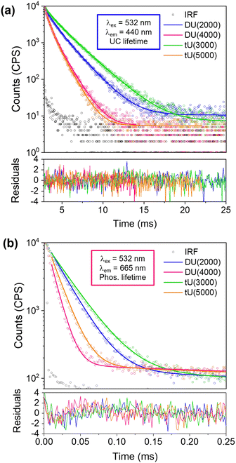
5![[thin space (1/6-em)]](https://www.rsc.org/images/entities/char_2009.gif) nm).64,65 DU(2000) had a higher threshold at 166 mW cm−2 which could be due its shorter triplet lifetime (Fig. 6), but UC is still seen from the low power density 2.3 mW cm−2.
nm).64,65 DU(2000) had a higher threshold at 166 mW cm−2 which could be due its shorter triplet lifetime (Fig. 6), but UC is still seen from the low power density 2.3 mW cm−2.
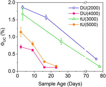 | ||
| Fig. 6 Effect of the ureasil host on the magnitude and stability of the UC quantum yield over time. λex = 532 nm, λem = 440 nm. | ||
The ΦTTET was also evaluated by comparing the phosphorescence intensity of ureasils loaded with only sensitiser only (0.1 mM PdOEP) against those with the sensitiser/emitter pair (0.1 mM PdOEP/10 mM DPA) – see Fig. S8 (ESI†). Lower MW ureasils showed more intense phosphorescence under ambient conditions. This potentially suggests there is increased oxygen protection in this system. Notably all ureasils demonstrate a high ΦTTET, especially tU(3000) and DU(2000), both with above 95% (Table 1).
| Ureasil | Φ UC (%) | I th (mW cm−2) | Φ PL (%) | Φ TTET (%) | 〈τUC〉f (ms) | 〈τPHOS〉g (with DPA) (μs) | 〈τPHOS〉g (no DPA) (μs) |
|---|---|---|---|---|---|---|---|
| a Upconversion quantum yield at excitation intensity of 1 W cm−2 (532 nm). b Threshold intensity determined from logarithmic plot of integrated UC emission intensity at varying 532 nm laser power. c Not measured. d Photoluminescence quantum yield of the emitter determined by the integrating sphere method (λex = 375 nm). e TTET calculated from average phosphorescence emission intensity with and without emitter present (see eqn S3 (ESI), λex = 532 nm, λem = 600–800 nm). f Average upconversion lifetime (λex = 532 nm, λem = 440 nm). g Average phosphorescence lifetime in absence or presence of DPA (λex = 532 nm, λem = 665 nm). All measurements performed under ambient conditions. Errors are the standard deviation of two measurements. | |||||||
| DU(2000) | 1.86 ± 0.05 | 166 | 81.4 ± 2.1 | 97 ± 2 | 16 ± 0.5 | 102 | 25 |
| DU(4000) | 0.71 ± 0.06 | —c | 78.4 ± 0.8 | 84 ± 3 | 10 ± 0.3 | 327 | 9 |
| tU(3000) | 1.67 ± 0.18 | 27 | 86.6 ± 2.0 | 95 ± 2 | 22 ± 2.5 | 59 | 25 |
| tU(5000) | 1.14 ± 0.14 | —c | 83.9 ± 1.3 | 92 ± 3 | 8 ± 0.6 | 182 | 8 |
Due to the bimolecular nature of TTA, the rate of TTA will show a quadratic dependence on the concentration of excited triplet emitters (and thus excitation intensity). In diffusion-controlled ideal solutions, a clear distinction between low (quadratic) and high (linear) excitation intensity regimes can often be discerned.21 However, in (semi)solid-state systems, a more gradual shift between the two regimes is more commonly observed,21,66 as is the case here (Fig. 4d). Transition to linear dependence with excitation intensity implies that the concentration of triplet excited emitters is sufficient to ensure a high probability of annihilation collisions within their excited state lifetime, leading to near-unity triplet relaxation by TTA. However, in solid-state systems, sensitiser/emitter pairs are under non-ideal diffusion-control: the mean free path of both chromophores is likely to be more restricted compared to fluid solution, which may lead to less random collisions. As such, the change in slope from linear to quadratic may be less well-defined, as idealised TTET behaviour competes with alternative relaxation processes such as sensitiser self-annihilation.67
Lifetime studies
We had expected the lower Tg's of the higher MW organic precursors (Table 2) would lead to a higher rate of molecular diffusion and therefore improved UC performance; yet we see the opposite trend. To explore why this occurs, we next investigated the UC decay kinetics. The UC emission is very long-lived (milliseconds) and display a rise-time that cannot easily be reconvoluted from the instrument response function (see Fig. S9, ESI†). As such, the decay lifetimes were determined by tail fits (Fig. 5a).67 Full details of the fitting parameters are available in Table S5 (ESI†). Two exponential decay components were required to fit the decays: a shorter-lived, minor component (f1 = 18–34%, τ1 = 5–11 ms) attributed to partially oxygen-quenched UC emission, and a longer-lived component attributed to the natural UC emission (f2 = 66–82%, τ2 = 11–22 ms). The average upconversion lifetime 〈τUC〉 follows the trend tU3000 > DU2000 > tU5000 = DU4000, which mirrors the calculated inorganic silica content (Table 2 and Table S4, ESI†). 〈τUC〉 decreases with increasing polymer host MW and reduced branching. Previous studies on poly(ethylene)-poly(ethylene glycol)-SiO2 block copolymers observed that the oxygen transfer rate (OTR) was reduced when the ratio of inorganic component was increased.68 Moreover, polymers with a lower MW organic component showed a lower OTR due to reduced chain mobility.69 It is therefore highly probable that these combined factors also determine the observed trends in the ureasil system. We note that while it has been reported that DPA can form an endoperoxide bridge with singlet molecular oxygen, providing a certain degree of intrinsic oxygen protection,70 this cannot explain the differences that arise here since the DPA concentration is identical in all ureasils under investigation.| Ureasil | Silica contenta (wt%) | Coherence length, Lb (Å) | Structural unit distance, db (Å) | Shrinkagec (%) | T g (°C) | Elastic modulus (MPa) | Bending modulus (MPa) |
|---|---|---|---|---|---|---|---|
| a Determined from the molecular weight of inorganic silica with respect to the MW of the ureasil (see ESI Section S1.2 and Table S1). b From PXRD (see ESI, Section S5.3). c Determined from the volume of the sol before casting and the final area of the solid ureasil when dried (see ESI, Section S1.2). | |||||||
| DU(2000) | 4.1 | 17.28 | 4.30 | 55.5 | −70 | 1.16 ± 0.002 | 4.93 ± 0.20 |
| DU(4000) | 2.1 | 15.55 | 4.34 | 50.3 | −73 | 0.53 ± 0.001 | 1.95 ± 0.21 |
| tU(3000) | 4.1 | 17.39 | 4.28 | 49.7 | −64 | 1.90 ± 0.004 | 9.39 ± 0.25 |
| tU(5000) | 2.5 | 15.64 | 4.35 | 40.8 | −82 | 0.97 ± 0.002 | 3.67 ± 0.66 |
The phosphorescence decays in air were also measured for sensitiser/emitter and sensitiser-only ureasils (Fig. 5b and Fig. S9b, Table S6 (ESI†), PdOEP = 0.1 mM in both systems). This system is unusual as the lifetime with the emitter present is longer – the opposite of the usual case. This is thought to be due to back-transfer of triplet from the DPA emitter extending the lifetime of phosphorescence.71 The shorter lifetimes in PdOEP doped ureasils could also be due to relatively high concentrations of PdOEP leading to self-annihilation due to TTA between excited PdOEP triplets at high excitation intensities.67
Long-term UC stability
Air-stability is a huge challenge in the field of TTA-UC and the demand for materials with inherent oxygen protection is high. However, the long term ΦUC over time in air is seldom reported. Fig. 6 shows the fluctuation in ΦUC for samples measured over nearly 3 months. Notably, DU(2000) and tU(3000) retained their activity over a significantly longer period (up to 76–78 days) than the samples with the lower %wt silica content. In contrast, ΦUC for DU(4000) and tU(5000) dropped off rapidly and was negligible after 24 days. Air-stability decreases with increasing polymer host molecular weight and reduced branching.For all samples, the loss in efficiency is likely due to two factors: atmospheric oxygen ingress into the ureasil leading to triplet quenching, and photobleaching of the chromophores over time. Fig. S10 (ESI†) shows the UV/Vis absorption spectra over time (up to 23 days post gelation). While the PdOEP absorption remains effectively constant in all ureasils, the DPA absorption decreases with time, suggesting photobleaching may be the primary factor. We note that ureasils themselves are typically photostable, with accelerated aging studies using intense UV irradiation (24 hours) leading to no change in optical performance.48
Effect of host structure on TTA-UC performance
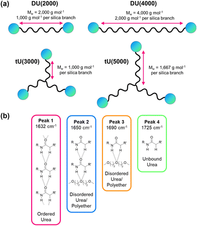
Our photophysical studies demonstrate that the relationship between the ureasil host structure and the TTA-UC performance is non-trivial. If we consider the di- or tri-branched series individually, a lower MW and higher silica content leads to ureasils with higher ΦUC and increased stability. However, if we compare analogues between the two series, the trends are less clear.Table 2 summarises the key structural, thermal, and mechanical properties of the undoped ureasils. All ureasils have a Tg well below 0 °C, as determined by dynamic mechanical analysis (DMA), indicating that at room temperature the polymer backbone should be in a viscous liquid or rubbery state with individual polymer chains moving freely (see also Fig. S12 and Table S7, ESI†). DMA measures viscoelasticity and gives a direct order of viscosity between ureasil samples, which is used as a proxy for chromophore diffusion rates. This below-ambient Tg suggests that all ureasils investigated should offer good chromophore solubility and a reasonable degree of mobility to facilitate the essential molecular collisions that for TTET. For both series, increasing the precursor chain length leads to a decrease in Tg, which is attributed to both an increase in chain flexibility68 and a decrease in the number of urea-silica linkages. This effect is more significant for the tri-branched series, for which the incidence of cross-linkages is inherently higher (Fig. 7a).
Further insight into the local organic structure can be obtained by examining the FTIR spectra in the amide I region (1600–1800 cm−1), which reveals the extent of hydrogen bonding (see Fig. 7b, Fig. S12 and Table S8, ESI†).44 Ureasils with a lower precursor MW have a lower proportion of free unbound urea groups (Peak 4, Fig. 7b and Fig. S12, ESI†) and weak, disordered hydrogen bonds (Peak 3, Fig. 7, and Fig. S12, ESI†) and a higher fraction of direct, ordered hydrogen- bonding from N–H to C![[double bond, length as m-dash]](https://www.rsc.org/images/entities/char_e001.gif) O on neighbouring chains (Peak 1). A higher contribution from ordered hydrogen-bonding peaks is linked with a higher Tg and more closely packed structure.44,47 Moreover, increased levels of hydrogen-bonding order have also been shown to decrease oxygen penetration in related organic–inorganic polymers.69
O on neighbouring chains (Peak 1). A higher contribution from ordered hydrogen-bonding peaks is linked with a higher Tg and more closely packed structure.44,47 Moreover, increased levels of hydrogen-bonding order have also been shown to decrease oxygen penetration in related organic–inorganic polymers.69
DU(2000) and tU(3000) showed the highest ΦUC – these samples also have the lower MW chain for the di-and tri-branched series, respectively. However, tri-branched samples will contain a more condensed silica network than di-branched samples of comparable MW. The silica content (wt%) in the sample is therefore a good indirect measure of the combined effects of branching and chain length. For both di- and tri-branched precursors, the lower MW leads to a higher silica content (both ca. 4.1%), due to the shorter distance between chain ends as illustrated schematically in Fig. 7a. This can be observed at the macroscopic level: ureasils with the lowest wt% silica are more flexible and bendy (Fig. S13, ESI†), and therefore have higher elastic and bending moduli (see Table 2, and Fig. S13, S14, ESI†). Similarly, tri-branched structures have higher bending moduli than their di-branched counterparts.
PXRD provides insight into the size and coherence of the silica domains and the distance between them (see Fig. S15 and Table S9, ESI†) at the sub-nanometer scale.53 Interestingly, while the structural unit distance is consistent across all samples (d ∼4.3 Å, from Bragg's law), the coherence length, L, over which the structural unit survives (i.e. the crystallite size) is longer for both DU(2000) and tU(3000). This is somewhat counterintuitive, since a more persistent and condensed silica network would be expected to reduce lumophore mobility. This suggests that the molecular collisions responsible for TTA-UC are primarily localised to the organic domains (which is reasonable based on solubility grounds), and that as long as the Tg is below room temperature, there will be sufficient mobility for these to occur.
To examine the effect of oxygen exclusion on the UC performance, a preliminary test was conducted on DPA (10 mM)/PdOEP (0.1 mM)-tU(3000) in which the precursor solution was degassed by nitrogen bubbling for 1 hr before gelation. A slight increase in 〈τUC〉 and large increase in 〈τPHOS〉 was observed (to 289 μs, Table S10, ESI†), and ΦUC increased to 2.39 ± 0.30% at 1 W cm−2. This indicates that while the ureasil structure provides some intrinsic oxygen barrier (as shown by the long stability), higher TTET rates and ΦUC could possibly be achieved with additional oxygen removal.
Conclusions
We have demonstrated ureasils as highly effective host materials for solid-state TTA-UC, achieving ΦUC up to 1.86% (at 1 W cm−2 excitation density) in ambient conditions. The UC efficiency varies with the ureasil host used. All ureasils studied inherit high optical transparency, mechanical strength, and oxygen protection from the inorganic silica nanodomains, whilst retaining the chromophore solubility, low Tg, flexibility and processability of organic polymers. However, it is the balance between the organic-to-inorganic ratio and the persistence length of the silica domains that determines both the absolute efficiency and long-term stability of the UC emission. Of the four ureasils studied, DU(2000) and tU(3000) contain the highest silica content and domain coherence length. We postulate that these structural features help provide increased oxygen protection, as shown by the enhanced triplet lifetime and ΦUC. Impressively, measurable UC emission is retained for both samples for >70 days without any special treatment or storage, including deoxygenation. This ability to operate in ambient conditions due to inherent oxygen protection is highly desirable for almost all TTA-UC applications. We are currently undertaking detailed studies of the O2 transmission rates and local diffusivity in these ureasils and structurally-related analogues to fully identify the key structure-function characteristics. The underpinning knowledge obtained through this investigation will inform the design of next generation hybrid host structures, with the goal of further enhancing the efficiency and long-term stability of TTA-UC in the solid-state.Conflicts of interest
There are no conflicts to declare.Acknowledgements
This work was funded by the European Research Council (ERC) under the European Union's Horizon 2020 research and innovation programme (Grant Agreement No. 818762 - SPECTRACON).References
- C. A. Parker and C. G. Hatchard, Proc. Chem. Soc., 1962, 269, 574–584 Search PubMed.
- C. A. Parker, C. G. Hatchard and T. A. Joyce, Nature, 1965, 205, 1282–1284 CrossRef CAS.
- S. H. C. Askes, V. C. Leeuwenburgh, W. Pomp, H. Arjmandi-Tash, S. Tanase, T. Schmidt and S. Bonnet, ACS Biomater. Sci. Eng., 2017, 3, 322–334 CrossRef CAS PubMed.
- Q. Dou, L. Jiang, D. Kai, C. Owh and X. J. Loh, Drug Discovery Today, 2017, 22, 1400–1411 CrossRef CAS PubMed.
- M. H. C. van Son, A. M. Berghuis, F. Eisenreich, B. de Waal, G. Vantomme, J. Gómez Rivas and E. W. Meijer, Adv. Mater., 2020, 32, 2004775 CrossRef CAS PubMed.
- T. Yu, Y. Liu, Y. Zeng, J. Chen, G. Yang and Y. Li, Chem. – Eur. J., 2019, 25, 16270–16276 CrossRef CAS PubMed.
- M. Uji, T. J. B. Zähringer, C. Kerzig and N. Yanai, Angew. Chem., Int. Ed., 2023, e202301506 CAS.
- D. Yildiz, C. Baumann, A. Mikosch, A. J. C. Kuehne, A. Herrmann and R. Göstl, Angew. Chem., Int. Ed., 2019, 58, 12919–12923 CrossRef CAS PubMed.
- M. J. Y. Tayebjee, D. R. McCamey and T. W. Schmidt, J. Phys. Chem. Lett., 2015, 6, 2367–2378 CrossRef CAS PubMed.
- J. Pedrini and A. Monguzzi, J. Photonics Energy, 2017, 8, 1 Search PubMed.
- D. Beery, T. W. Schmidt and K. Hanson, ACS Appl. Mater. Interfaces, 2021, 13, 32601–32605 CrossRef CAS PubMed.
- Y. C. Simon and C. Weder, J. Mater. Chem., 2012, 22, 20817 RSC.
- Y. Zhou, F. N. Castellano, T. W. Schmidt and K. Hanson, ACS Energy Lett., 2020, 5, 2322–2326 CrossRef CAS.
- N. Yanai, K. Suzuki, T. Ogawa, Y. Sasaki, N. Harada and N. Kimizuka, J. Phys. Chem. A, 2019, 123, 10197–10203 CrossRef CAS PubMed.
- T. N. Singh-Rachford and F. N. Castellano, Coord. Chem. Rev., 2010, 254, 2560–2573 CrossRef CAS.
- DECC, 2011, 83–86.
- S. Baluschev, T. Miteva, V. Yakutkin, G. Nelles, A. Yasuda and G. Wegner, Phys. Rev. Lett., 2006, 97, 143903 CrossRef CAS PubMed.
- R. R. Islangulov, J. Lott, C. Weder and F. N. Castellano, J. Am. Chem. Soc., 2007, 129, 12652–12653 CrossRef CAS PubMed.
- M. J. Bennison, A. R. Collins, B. Zhang and R. C. Evans, Macromolecules, 2021, 54, 5287–5303 CrossRef CAS PubMed.
- B. Joarder, N. Yanai and N. Kimizuka, J. Phys. Chem. Lett., 2018, 9, 4613–4624 CrossRef CAS PubMed.
- V. Gray, K. Moth-Poulsen, B. Albinsson and M. Abrahamsson, Coord. Chem. Rev., 2018, 362, 54–71 CrossRef CAS.
- P. Bharmoria, N. Yanai and N. Kimizuka, Gels, 2019, 5, 18 CrossRef CAS PubMed.
- R. Vadrucci, C. Weder and Y. C. Simon, Mater. Horiz., 2015, 2, 120–124 RSC.
- H. Zhou, J. Lin, S. Wan and W. Lu, Phys. Chem. Chem. Phys., 2022, 24, 29151–29158 RSC.
- L. Huang, E. Kakadiaris, T. Vaneckova, K. Huang, M. Vaculovicova and G. Han, Biomaterials, 2019, 201, 77–86 CrossRef CAS PubMed.
- H. Nishikiori, M. Takeshita, Y. Komatsu, H. Satozono and K. Teshima, ACS Omega, 2018, 3, 8529–8536 CrossRef CAS PubMed.
- T. Schloemer, P. Narayanan, Q. Zhou, E. Belliveau, M. Seitz and D. N. Congreve, ACS Nano, 2023, 17, 3259–3288 CrossRef CAS PubMed.
- B. Zhang, K. D. Richards, B. E. Jones, A. R. Collins, R. Sanders, S. R. Needham, P. Qian, A. Mahadevegowda, C. Ducati, S. W. Botchway and R. C. Evans, Angew. Chem., 2023, 135, e202308602 CrossRef.
- Y. C. Simon and C. Weder, Nat. Mater., 2015, 14, 864–865 CrossRef CAS PubMed.
- C. Healy, L. Hermanspahn and P. E. Kruger, Coord. Chem. Rev., 2021, 432, 213756 CrossRef CAS.
- R. Vadrucci, A. Monguzzi, F. Saenz, B. D. Wilts, Y. C. Simon and C. Weder, Adv. Mater., 2017, 29, 1702992 CrossRef PubMed.
- P. Bharmoria, S. Hisamitsu, Y. Sasaki, T. S. Kang, M. A. Morikawa, B. Joarder, K. Moth-Poulsen, H. Bildirir, A. Mårtensson, N. Yanai and N. Kimizuka, J. Mater. Chem. C, 2021, 9, 11655–11661 RSC.
- T. N. Singh-Rachford, J. Lott, C. Weder and F. N. Castellano, J. Am. Chem. Soc., 2009, 131, 12007–12014 CrossRef CAS PubMed.
- H. Yang, S. Guo, B. Jin, Y. Luo and X. Li, Polym. Chem., 2022, 13, 4887–4894 RSC.
- A. Monguzzi, M. Mauri, A. Bianchi, M. K. Dibbanti, R. Simonutti and F. Meinardi, J. Phys. Chem. C, 2016, 120, 2609–2614 CrossRef CAS.
- S. H. Lee, J. R. Lott, Y. C. Simon and C. Weder, J. Mater. Chem. C, 2013, 1, 5142–5148 RSC.
- R. Karpicz, S. Puzinas, V. Gulbinas, A. Vakhnin, A. Kadashchuk and B. P. Rand, Chem. Phys., 2014, 429, 57–62 CrossRef CAS.
- S. Raišys, S. Juršėnas, Y. C. Simon, C. Weder and K. Kazlauskas, Chem. Sci., 2018, 9, 6796–6802 RSC.
- T. Kashino, M. Hosoyamada, R. Haruki, N. Harada, N. Yanai and N. Kimizuka, ACS Appl. Mater. Interfaces, 2021, 13, 13676–13683 CrossRef CAS PubMed.
- T. Kashino, R. Haruki, M. Uji, N. Harada, M. Hosoyamada, N. Yanai and N. Kimizuka, ACS Appl. Mater. Interfaces, 2022, 14, 22771–22780 CrossRef CAS PubMed.
- S. Amberg-Schwab, M. Hoffmann, H. Bader and M. Gessler, J. Sol-Gel Sci. Technol., 1998, 13, 141–146 CrossRef CAS.
- S. Amberg-Schwab, U. Weber, A. Burger, S. Nique and R. Xalter, Monatsh. Chem., 2006, 137, 657–666 CrossRef CAS.
- S. Sakka, in Handbook of Sol–gel Science and Technology, Kluwer Academic Publishers, 2005, p. 455 Search PubMed.
- V. de Zea Bermudez, L. D. Carlos and L. Alcácer, Chem. Mater., 1999, 11, 569–580 CrossRef.
- L. D. Carlos, V. De Zea Bermudez, R. A. Sá Ferreira, L. Marques and M. Assunção, Chem. Mater., 1999, 11, 581–588 CrossRef CAS.
- A. Collins, T. Southern, G. Lyu, M. J. Bennison and R. C. Evans, in Photosensitive Materials and their Applications, ed. R. R. McLeod, Y. Tomita, J. T. Sheridan and I. Pascual Villalobos, SPIE, 2020, vol. 11367, p. 32 Search PubMed.
- I. Meazzini, C. Blayo, J. Arlt, A. T. Marques, U. Scherf, H. D. Burrows and R. C. Evans, Mater. Chem. Front., 2017, 1, 2271–2282 RSC.
- A. Kaniyoor, B. Mckenna, S. Comby and R. C. Evans, Adv. Opt. Mater., 2016, 4, 444–456 CrossRef CAS.
- M. M. Nolasco, P. M. Vaz, V. T. Freitas, P. P. Lima, P. S. André, R. A. S. Ferreira, P. D. Vaz, P. Ribeiro-Claro and L. D. Carlos, J. Mater. Chem. A, 2013, 1, 7339–7350 RSC.
- M. Fernandes and V. de Zea Bermudez, in Chemical Solution Synthesis for Materials Design and Thin Film Device Applications, Elsevier, 2021, pp. 439–475 Search PubMed.
- A. Bastos, B. McKenna, M. Lima, P. S. André, L. D. Carlos, R. C. Evans and R. A. S. Ferreira, ACS Omega, 2018, 3, 13772–13781 CrossRef CAS PubMed.
- G. Lyu, T. J. F. Southern, B. L. Charles, M. Roger, P. Gerbier, S. Clément and R. C. Evans, J. Mater. Chem. C, 2021, 9, 13914–13925 RSC.
- I. Meazzini, N. Willis-Fox, C. Blayo, J. Arlt, S. Clément and R. C. Evans, J. Mater. Chem. C, 2016, 4, 4049–4059 RSC.
- J.-H. Kim, F. Deng, F. N. Castellano and J.-H. Kim, Chem. Mater., 2012, 24, 2250–2252 CrossRef CAS.
- L. Naimovičius, P. Bharmoria and K. Moth-Poulsen, Mater. Chem. Front., 2023, 7, 2297–2315 RSC.
- E. F. Molina, L. Marçal, H. W. Pereira De Carvalho, E. J. Nassar and K. J. Ciuffi, Polym. Chem., 2013, 4, 1575–1582 RSC.
- J. V. Morris, M. A. Mahaney and J. R. Huber, J. Phys. Chem., 1976, 80, 969–974 CrossRef CAS.
- D. G. Congrave, B. H. Drummond, V. Gray, A. D. Bond, A. Rao, R. H. Friend and H. Bronstein, Polym. Chem., 2021, 12, 1830–1836 RSC.
- L. Fu, R. A. Sá Ferreira, M. Fernandes, S. C. Nunes, V. de Zea Bermudez, G. Hungerford, J. Rocha and L. D. Carlos, Opt. Mater., 2008, 30, 1058–1064 CrossRef CAS.
- A. Monguzzi, R. Tubino, S. Hoseinkhani, M. Campione and F. Meinardi, Phys. Chem. Chem. Phys., 2012, 14, 4322 RSC.
- L. Wei, C. Fan, M. Rao, F. Gao, C. He, Y. Sun, S. Zhu, Q. He, C. Yang and W. Wu, Mater. Horiz., 2022, 9, 3048–3056 RSC.
- F. Saenz, A. Ronchi, M. Mauri, R. Vadrucci, F. Meinardi, A. Monguzzi and C. Weder, Adv. Funct. Mater., 2021, 31, 2004495 CrossRef CAS.
- N. A. Durandin, J. Isokuortti, A. Efimov, E. Vuorimaa-Laukkanen, N. V. Tkachenko and T. Laaksonen, J. Phys. Chem. C, 2019, 123, 22865–22872 CrossRef CAS.
- A. J. Carrod, V. Gray and K. Börjesson, Energy Environ. Sci., 2022, 15, 4982–5016 RSC.
- T. Ogawa, N. Yanai, A. Monguzzi and N. Kimizuka, Sci. Rep., 2015, 5, 1–9 Search PubMed.
- P. Bharmoria, H. Bildirir and K. Moth-Poulsen, Chem. Soc. Rev., 2020, 49, 6529–6554 RSC.
- F. Edhborg, A. Olesund and B. Albinsson, Photochem. Photobiol. Sci., 2022, 21, 1143–1158 CrossRef CAS PubMed.
- M. Minelli, M. G. De Angelis, F. Doghieri, M. Marini, M. Toselli and F. Pilati, Eur. Polym. J., 2008, 44, 2581–2588 CrossRef CAS.
- M. Toselli, F. Pilati, M. Marini, F. Doghieri, M. G. De Angelis and M. Minelli, Eur. Polym. J., 2008, 44, 3256–3263 CrossRef CAS.
- W. Drews, R. Shimidt and H. D. Brauer, Chem. Phys. Lett., 1980, 70, 84–88 CrossRef CAS.
- M. Kinoshita, Y. Sasaki, S. Amemori, N. Harada, Z. Hu, Z. Liu, L. K. Ono, Y. Qi, N. Yanai and N. Kimizuka, ChemPhotoChem, 2020, 4, 5271–5278 CrossRef CAS.
Footnotes |
| † Electronic supplementary information (ESI) available: Materials and methods; synthetic procedures; silica wt% calculations; additional data from: chromophore concentration determination studies, UV-vis absorption spectroscopy, steady-state PL spectroscopy, UC emission spectra, time-resolved emission lifetime fitting, dynamic mechanical analysis, FTIR deconvolution and fitting, XRD deconvolution and fitting, 4-point flexural tests, uniaxial tensile tests; photographs and video ambient TTA-UC activity in ureasils. See DOI: https://doi.org/10.1039/d4tc00562g |
| ‡ Present address: State Key Laboratory of Functional Materials and Devices for Special Environmental Conditions; Xinjiang Key Laboratory of Electronic Information Materials and Devices; Xinjiang Technical Institute of Physics & Chemistry, CAS, 40-1 South Beijing Road, Urumqi 830011, China. |
| This journal is © The Royal Society of Chemistry 2024 |

