Dual-atom catalysts with microenvironment regulation for water electrolysis
Ruoqing
Xu†
a,
Rongbo
Sun†
b,
Hai-Qun
Xu
c,
Gang
Xie
 d and
Jingjie
Ge
 *a
*a
aDepartment of Applied Biology and Chemical Technology, The Hong Kong Polytechnic University, Hung Hom, Kowloon, Hong Kong 999077, China. E-mail: jingjie.ge@polyu.edu.hk
bSinochem Holdings Co Ltd, Sinochem Energy High-tech Co Ltd, 2 West Tieying Middle Rd, Fengtai District, Beijing, 100031, China
cSchool of Materials and Chemical Engineering, Anhui Jianzhu University, Hefei, Anhui 230601, China
dState Key Laboratory of Oil & Gas Reservoir Geology and Exploitation, Southwest Petroleum University, Chengdu, Sichuan 610500, China
First published on 1st August 2024
Abstract
Dual-atom catalysts (DACs) have emerged as highly promising and efficient catalysts for water electrolysis, primarily due to their distinct dual-atom site effects. Optimizing the catalytic performance of DACs involves precise regulation of their microenvironment, encompassing elemental compositions, electronic distributions, geometric configurations, and coordination environment. Despite growing research interests, a comprehensive understanding of how these microenvironmental regulations impact DAC performance remains elusive. This review seeks to elucidate the influence of microenvironmental regulation on the efficiency of DACs in water electrolysis. We begin by categorizing DACs into three types based on their dual-atom configurations: homonuclear, heteronuclear, and molecular, followed by specific analyses of the different connection modes between dual-atom sites. Subsequently, we provide a comprehensive overview of the relationships between microenvironment regulation and the resulting properties of DACs, highlighting the elemental, electronic, geometric, and coordination effects. Additionally, we review recent research and theoretical advancements in water electrolysis applications of DACs under various pH conditions, demonstrating how microenvironment regulation enhances their catalytic performances. We conclude by discussing the challenges and prospects of DACs, offering insights into potential future research directions.
1. Introduction
With the rapid growth of energy required by society, the fast-growing fossil fuel consumption has led to environmental pollution issues.1,2 Consequently, producing sustainable, eco-friendly, and renewable energy sources has emerged as one of our society's foremost challenges.3 Hydrogen is currently the most promising clean energy support. This is attributed to its production of only water without carbon dioxide or other harmful gases, coupled with its high energy conversion efficiency during the combustion process.4 Water electrolysis is one of the most efficient methods to produce hydrogen, involving the hydrogen evolution reaction (HER) at the cathode and the oxygen evolution reaction (OER) at the anode. Water electrolysis offers several advantages, including its environmentally friendly nature and cost-effectiveness, making it a promising solution for addressing energy and environmental challenges.5,6 Specifically, developing highly active and stable catalysts is crucial to improving efficiency and reducing the cost of hydrogen production by water electrolysis. Initially, precious metal catalysts such as platinum (Pt) and iridium (Ir) garnered significant attention due to their exceptional catalytic activity and stability. However, their widespread application is impeded by their high cost and scarcity.7,8One of the practical approaches to address this problem is to downsize the active metal catalysts from bulk to atomically dispersed atoms while maintaining their excellent electrocatalytic performance.9,10 Atomically dispersed catalysts generally offer specific coordination microenvironments and optimal active sites, maximizing atomic efficiency and preserving crucial catalytic properties.5,11,12 Single-atom catalysts (SACs) with a single active center have garnered extensive and intensive research attention due to their outstanding metal dispersion, high atomic utilization, and excellent catalytic performance.13–15 However, SACs also have some drawbacks, such as low metal loading and isolated active sites, which significantly limit their diverse catalytic applications.16,17 Moreover, as research on bifunctional reaction catalysis progresses, SACs with a fixed adsorption mode can potentially hinder their multiatomic catalytic pathways.18 Recently, dual-atom catalysts (DACs) have been further developed and functionalized based on SACs.19,20 DACs are catalysts composed of two metal atoms coordinated in a specific configuration on a support material.21–23 The interactions between these two centers give each metal atom a distinctive electronic and atomic structure, setting them apart from their isolated single-atom counterparts. The two active sites synergistically regulate the activation and adsorption energies of reaction intermediates.24,25 DACs possess several advantages and overcome drawbacks of SACs. For example, DACs can anchor more metal atoms at a single adsorption site than SACs, allowing for higher metal atom loadings. Besides, DACs provide adjacent unsaturated coordination sites capable of absorbing multiple reactants simultaneously, breaking the catalytic linear relationships on conventional SACs during reactions.16 This feature facilitates various adsorption modes for key intermediates, optimizing reaction pathways and significantly boosting catalytic activity and selectivity. However, designing efficient DACs is particularly challenging due to different possible combinations of dual metal sites, along with the complexities of precisely controlling these sites and their interactions.
Within DACs, interactions manifest among adjacent metal atoms and between these metal centers and their substrates. These interactions are subject to various influences, such as elemental composition, electronic properties, geometric configurations, and coordination effects. Significantly, these factors' impact depends on the microenvironment surrounding the active sites.26,27 This precise regulation of interactions within the interconnected active sites in DACs is known as microenvironmental regulation.16,26,28 This regulation optimizes the overall catalytic performance, leading to significant improvements in the efficiency and durability of hydrogen production through electrochemical water electrolysis. However, while published reviews often focus on DACs with homo- or hetero-centers, and are mainly focused on their synthetic methods and catalytic applications, how two metal active centers synergistically facilitate the water electrolysis process has not been comprehensively summarized.
Herein, we provide an overview of the microenvironment regulation of DACs for electrochemical water electrolysis over recent years. This review includes a classification of DACs based on different metal centers and discusses the microenvironment regulation by analyzing the site effects between dual-atom sites, as well as the corresponding structure–performance relationships through both the theoretical and experimental findings. Firstly, DACs will be discussed in homonuclear, heteronuclear, and molecular three categories, followed by specific analyses of the different connection modes between dual-atom units. Subsequently, we provide insights into how microenvironmental regulation influences their catalytic properties by investigating the dual-atom site effect of DACs, including elemental, electronic, geometrical, and coordination effects. This regulation includes self-regulation by the metal atoms (elemental and electronic effects) and regulation by surrounding ligands or supporting materials (geometrical and coordination effects). Furthermore, a comprehensive overview will be provided on the advanced catalytic applications of DAC in water electrolysis reactions, including HER, OER, and overall water splitting under different pH environments. A comprehensive analysis summarizes a range of DACs suitable for water electrolysis under specific conditions. Finally, the summary, challenges, and prospects for developing DACs are presented. An in-depth investigation into the development of DACs and their microenvironmental regulation will contribute significantly to advancing the comprehension of DACs. Additionally, it will provide guidance and references for further research and the application of DACs in catalysis.
2. Categories of DACs
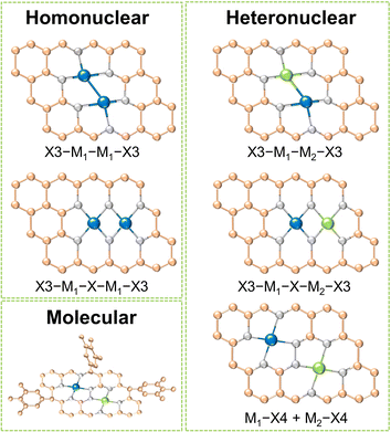
Dual-metal sites in DACs exhibit various configurations, including direct metal bonding, heteroatom bridging (such as N, O, P, S, etc.), and two independently isolated metal sites. These arrangements can host dual metal atoms as homonuclear pairs, heteronuclear pairs, or molecular entities. As shown in Fig. 1, for homo- and heteronuclear, these specific structures are represented as “X3–M1–M1–X3”, “X3–M1–X–M1–X3”, “X3–M1–M2–X3”, “X3–M1–X–M2–X3” and “M1–X4 + M2–X4”, respectively, where M1 and M2 denote the central metal atoms, and X represents coordinated heteroatoms.16 It should be highlighted that dual-atom molecular catalysts (DAMCs), which feature either homonuclear or heteronuclear sites, are discussed separately in this review due to their distinctive structure with functional groups. The synergistic interactions between homonuclear or heteronuclear dual-atoms are critically influenced by their microenvironments, thereby optimizing the catalytic kinetics and selectivity of the diatomic sites. This section categorizes DACs into three types: homonuclear, heteronuclear, and molecular, with an emphasis on their composition and structures. By providing concise introductions and examples, we summarized the distinctions and characteristics of these three categories of DACs.2.1 Homonuclear DACs
Homonuclear DACs are a class of catalysts in which the active sites are composed of two identical metal atoms connected through a metal bond or bridged by heteroatoms. By designing the metal centers and their coordination environments, researchers can tune the electronic structure and reactivity of homonuclear DACs to optimize their performance in specific reactions.9 In this section, the discussion focuses on homonuclear DACs under the two connection modes, namely direct metal-bonded (“X3–M1–M1–X3”) and heteroatom bridged (“X3–M1–X–M1–X3”).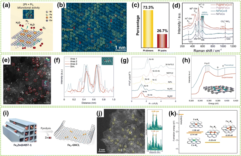 | ||
| Fig. 2 Structure characterization of homonuclear DACs connected by metal bonds. (a) Schematic diagram of the HER and OER activity of Pt dimers and Pt pairs on NiFeCo-E for water splitting catalysis. (b) Atomic-resolution HAADF-STEM image of Pt@NiFeCo-E. (c) A statistical diagram of Pt dimers and Pt2. (d) Raman spectra of NiFeCo, NiFeCo-E, Pt@NiFeCo, and Pt@NiFeCo-E32 (reproduced with permission from ref. 32 copyright 2024, Elsevier). (e) HAADF-STEM image of Ni2NC, the dimers are depicted in red circles. Scale bar, 2 nm. Inset: the Ni–Ni atoms in the observed diatomic pair. Scale bar: 0.25 nm (area 1) and 0.5 nm (area 2). (f) Atomic distance of dual atoms in the experimental and simulated (Sim.) STEM images. Inset: The theoretical model is based on the simulated STEM image using quantitative STEM software. Scale bar, 0.25 nm. (g) FT of k3-weighted Ni K edge EXAFS experimental data for Ni foil, NiO, NiPc, Ni1NC, and Ni2NC. (h) A comparison between the experimental XANES spectrum and the theoretical spectrum for Ni2NC. The main features reproduced are highlighted at point of A–E. The grey, turquoise, and purple spheres represent carbon, nitrogen, and nickel atoms, respectively. The Ni atoms with red circles mean the adsorbing atoms in the XANES spectrum33 (reproduced with permission from ref. 33 copyright 2022, Springer Nature). (i) Heteroatom modulator approach for fabricating dual-atom iron catalysts on carbon layer (Fe: orange; Zn: purple). (j) HAADF-STEM image of Fe2-GNCL and intensity profiles (top and bottom) from the atomic sites 1 and 2. (k) Ef of Fe/Co–N4, Fe2–N6, and Fe3–N4 moieties from graphene34 (reproduced with permission from ref. 34 copyright 2020, John Wiley and Sons). | ||
Except for anchoring and stabilizing the diatomic active site by creating substrate vacancies, utilizing specialized synthetic strategies to stabilize metal dimers is a viable approach based on the inherent tendency of metal atoms and clusters to polymerize. For example, Wei et al. adopt a “Heteroatom Modulator Approach” (HMA) to prevent the aggregation of iron atoms into nanoclusters by substituting Fe2+ with other metal ions like Zn2+ or Co2+ (Fig. 2i).34 The trinuclear complexes (Fe2Zn/Fe2Co) were immobilized on metal–organic frameworks (MOFs), followed by thermal evaporation of Zn atoms, resulting in a stable Fe2-GNCL (graphitized nitrogen-doped carbon layer). In Fig. 2j, the HAADF-STEM image and the accompanying intensity distribution map reveal a well-dispersed dual-site with a distance of approximately 2.6 Å on Fe2-GNCL. Besides, the Fe2–N6 fraction with the lowest formation energies (Ef) displays more excellent stability compared to the hypothesized Fe trimer cluster, indicating its optimal coordination configuration (Fig. 2k). In another study, Zhang et al. successfully synthesized supported Pd2 DAC using the anion replacement deposition–precipitation (ARDP) method.35 The atomic dispersion and metal–metal coordination structure of Pd2 DAC were demonstrated using the aberration-corrected (AC) HAADF-STEM, XAFS, and X-ray photoelectron spectroscopy (XPS) imaging techniques.
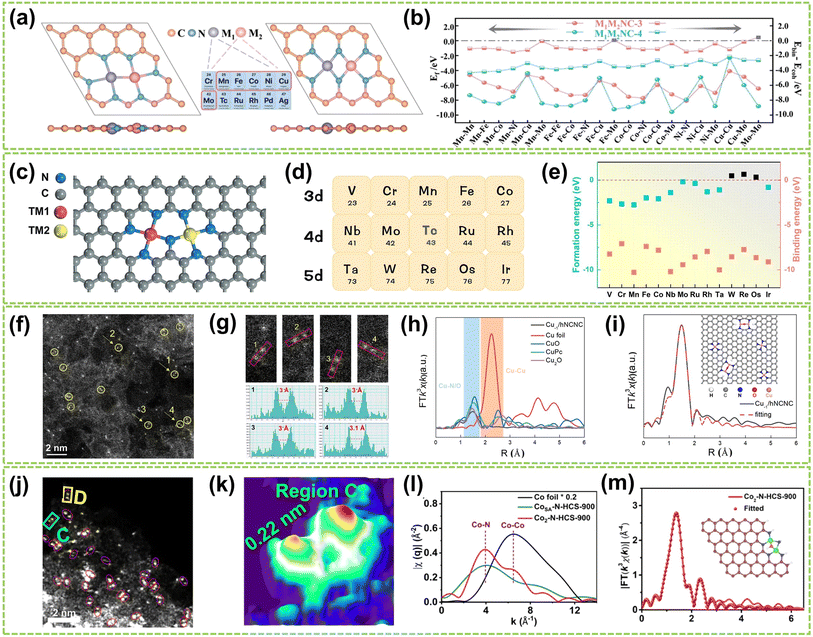 | ||
| Fig. 3 Structure characterization of homonuclear DACs connected by heteroatomic bridges. (a) The top and side views of optimized M1M2NC-3 and M1M2NC-4. (b) Ef and differences between the binding and cohesive energies of DACs (ΔEb-c)37 (reproduced with permission from ref. 37 copyright 2022, RSC). (c) Structure of N-bridged M1–N–M2/NC. (d) 14 transition metals are taken into account in this work. (e) Ef and Eb of M1–N–M1/NC38 (reproduced with permission from ref. 38 copyright 2023, Springer Nature). (f) HAADF-STEM image showing twinned Cu atoms (circled) and isolated Cu atoms. (g) Corresponding enlargement of the sites 1–4 in (f) and intensity profiles. (h) FT-EXAFS spectra of Cu−1/hNCNC and the references. (i) FT-EXAFS fitting curve of the Cu K-edge in R-space for Cu−1/hNCNC and the corresponding structure diagram39 (reproduced with permission from ref. 39 copyright 2024, ACS). (j) AC HAADF-STEM images (Co dual atoms marked by red circles). (k) 3D atom-overlapping Gaussian-function fitting map in (j) for Co2–N-HCS-900. (l) q-Space magnitude comparisons of Co foil, CoSA–N-HCS-900, and Co2–N-HCS-900. (m) k3-Weighted EXAFS fitting curves at R space for Co2–N-HCS-900 (inset: schematic structure of Co2N5 models; green: Co, blue: N, red: O)40 (reproduced with permission from ref. 40 copyright 2023, Springer Nature). | ||
Based on these theoretical guidances, Xu and co-workers recently successfully developed a highly dispersed Cu-based DAC using Cu2O as a precursor and hierarchical NC nanocage (hNCNC) as support.39 As shown in Fig. 3f, HAADF-STEM imaging revealed the presence of Cu⋯Cu pairs with a spacing of 3.0–3.1 Å, indicating the formation of Cu⋯Cu–N4 dual-metal sites and Cu–N4 monometallic sites. These sites were facilitated due to the mesopores of ca. 0.6 nm and abundant nitrogen doping provided by h-NCNC. The random selection of four dual-metal sites revealed an average atomic distance of 3 Å, shown in Fig. 3g, longer than that in Cu crystals (2.556 Å), which confirms the resemblance between twinned copper atomic sites and the Cu–O–Cu moieties present in Cu2O. The FT k3-weighted EXAFS oscillation and the fitting of the EXAFS spectrum demonstrate the exitance of Cu–O–Cu moieties in Cu−1/hNCNC (Fig. 3h–i). Similarly, Wang et al. developed a general nanoparticle-to-single-atom-to-dual-atom (NP-to-SA-to-DA) aerosolization and sintering strategy for synthesizing the Co2N5 dual atoms supported on nitrogen-doped HCS (Co2–N-HCS-900).40 This approach was further proven to be effective in fabricating 22 different DACs. As a typical example, the AC HAADF-STEM image of Co2–N-HCS-900 (Fig. 3j) exhibited numerous uniformly distributed bright spots, representing Co atoms on the carbon framework. Notably, a significant portion of Co atoms were observed adjacent to each other (highlighted by red circles), forming Co2 dual atoms with an approximate Co–Co distance of ca. 0.22 nm (Fig. 3k). As shown in Fig. 3l, the comparison of single-atom and dual-atom sample curves in the FT-EXAFS fitting curve clearly shows the generation of Co–Co bonds during the formation of DA. In contrast, only the Co–N pathway was observed in CoSA–N-HCS-900. The average coordination numbers of Co–N/O (3.9) and Co–Co (0.8) bonds in Co2–N-HCS-900 preliminarily suggested most Co atoms are bonded with 1 Co and 3 N (and 1 O) atoms. DFT calculations further confirmed the structure to be Co2N5–O, as illustrated in Fig. 3m.
2.2 Heteronuclear DACs
Heteronuclear DACs are a class of catalysts where the active sites consist of two distinct metal atoms.41 Compared to homonuclear DACs composed of two identical metal atoms, heteronuclear DACs feature different metal combinations, leading to a wide array of metal–metal interactions and electronic structures.42 This diversity imparts unique catalytic properties to heteronuclear DACs, allowing for precise regulation of reactivity and selectivity in catalytic reactions.43 Therefore, the catalytic performance of heteronuclear DACs is significantly enhanced. In this subchapter, heteronuclear DACs are classified into three categories: direct metal-bonded DACs (“X3–M1–M2–X3”), heteroatom-bridged DACs (“X3–M1–X–M2–X3”), and DACs with isolated sites (“M1–X4 + M2–X4”).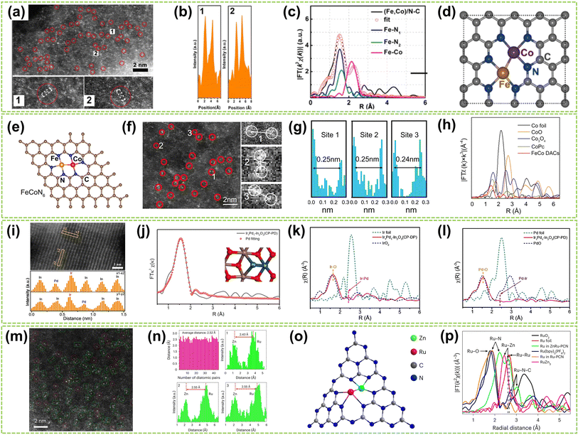 | ||
| Fig. 4 Structure characterization of heteronuclear DACs connected by metal bonds. (a) HAADF-STEM of (Fe, Co)/N–C, showing Fe–Co dual sites dominant in (Fe, Co)/N–C. (b) Corresponding intensity profiles were obtained on the zoomed areas in panel (a). (c) Fe K-edge EXAFS fittings of (Fe, Co)/N–C and reference samples. (d) Proposed architectures of Fe–Co dual sites44 (reproduced with permission from ref. 44 copyright 2017, ACS). (e) The proposed model of Fe–Co DACs sites. (f) AC HAADF-STEM image of Fe–Co DACs and some Fe–Co diatomic sites are highlighted by red circles (the red circles 1, 2, and 3 are partially enlarged on the right). (g) Intensity profiles of the three sites in (f). (h) FT-EXAFS spectra of Co45 (reproduced with permission from ref. 45 copyright 2023, Springer Nature). (i) The linear scanning profile along the region of the marked orange rectangles and the corresponding intensity of the atoms. (j) Pd fits of EXAFS spectra of the dual-atom Ir1Pd1–In2O3 (CP-PD) catalyst (inset: the simulated dual-atom Pd–Ir configuration). EXAFS spectra of (k) Ir L-edge and (l) Pd K-edge over dual-atom Ir1Pd1–In2O3 (CP-PD) catalyst46 (reproduced with permission from ref. 46 copyright 2024, John Wiley and Sons). (m) AC HAADF-STEM image of ZnRu–PCN. (n) Statistics of diatomic distance and line-scanning intensity profiles obtained from (m), with the average distance being 2.5 Å. (o) The structures of ZnRu–PCN. (p) FT-EXAFS curves for ZnRu–PCN, Ru–PCN, and the references. k, k space; χ(k), the wavelength of k space47 (reproduced with permission from ref. 47 copyright 2024, Springer Nature). | ||
Although transition metal-based DACs demonstrate outstanding catalytic properties, their stability is often compromised under harsh reaction conditions compared to the noble metal catalysts, underscoring the critical demand for advanced noble metal-based DACs. For example, Chen et al. employed photo-induced excitation to precisely position heteronuclear palladium atoms around the iridium atoms supported by indium oxide to form dual-metal Ir–Pd sites.46 They employ light as the driving force. The short lifetime of the photogenerated electrons facilitates their rapid spillover and deposition near the single-atom site. This ensures that another atom can be precisely deposited near the location of the existing single atom, enabling the controlled fabrication of the desired diatomic configuration. In Fig. 4i, the different Z-contrasts between Ir/Pd atoms and the In2O3 support were compared, and the corresponding atomic types were identified using line profiles. The EXAFS spectra of both Ir and Pd further confirm the above argument by the prominent peak at approximately 2.46 Å, which correlates with the length of the Ir–Pd bond in a model featuring In2O3-supported Ir–Pd dual-atom sites (Fig. 4j and k). Furthermore, a model of In2O3-supported Ir–Pd structure was established through EXAFS fitting, in which the distance between Ir and Pd (2.5 Å) closely matches with the results of EXAFS and line profiles in HAADF-STEM (Fig. 4l). This finding confirms the existence of Ir–Pd dual-metal pairs within such a structure. In another work, Zhao and co-workers recently provided a comprehensive overview of heteronuclear DACs.47 Polymer carbon nitride (PCN) was employed as the substrate, and the “navigate and localize” strategy was exemplified using ZnRu–PCN DAC. This strategy precisely constructed a heteronuclear ZnRu–PCN DAC using electronic accumulation on zinc sites to connect the ruthenium centers. In Fig. 4m and n, numerous dual-atom sites (green-boxed region) with an average distance of approximately 2.52 Å between adjacent sites were observed, inferring the dimeric structure (Fig. 4o). FT-EXAFS conducted a further analysis of the microstructure. As shown in Fig. 4p, peaks around 2.61 Å and 2.24 Å in the FT-EXAFS spectrum were observed in ZnRu PCN, attributed to the Ru–Zn and Ru–N pathways, respectively. At higher R values, no appreciable peaks for Ru–Ru were observed, confirming that most Ru atoms exist in single-atom form and coordinate with the Zinc atom in ZnRu DAC.
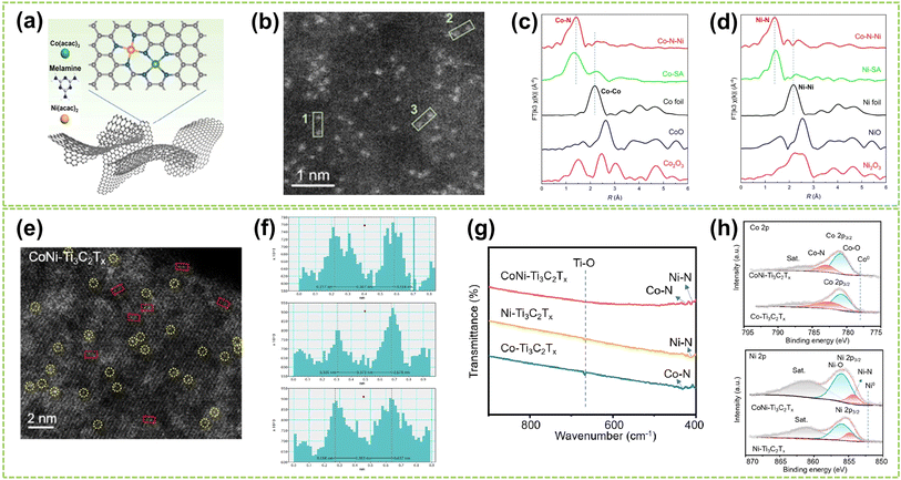 | ||
| Fig. 5 Structure characterization of heteronuclear DACs connected by heteroatomic bridges. (a) Schematic diagram of the polymerization-pyrolysis synthesis method of Co–N–Ni. (b) AC HAADF-STEM image of Co–N–Ni. The bright spots in the green box represent the Co, Ni dual-atom. (c) Co K-edge and (d) Ni K-edge FT-EXAFS spectra of Co–N–Ni DAC, Co/Ni-SA, and the references52 (reproduced with permission from ref. 52 copyright 2023, ACS). (e) HAADF-STEM images of CoNi–Ti3C2Tx, where bright spots corresponding to single metal atoms are marked by yellow circles, and possible Co–Ni atomic pairs are highlighted by red rectangles. (f) Intensity profiles were obtained on adjacent metal atomic pairs, taken from three different sites marked by red rectangles in (e). (g) FTIR spectra of CoNi–Ti3C2Tx, Ni–Ti3C2Tx, and Co–Ti3C2Tx composites. (h) Above: Co 2p and below: Ni 2p high-resolution XPS spectra of CoNi–Ti3C2Tx and Co–Ti3C2Tx composites53 (reproduced with permission from ref. 53 copyright 2024, ACS). | ||
For heteroatomic bridged heteronuclear, besides CoNi DACs as mentioned above, there has been extensively reported on other types of heteroatomic bridging diatomic materials.54,55 For instance, Zhang et al. synthesized ten different DACs using a macrocyclic precursor-mediated approach, including six homonuclear species (Fe2, Co2, Ni2, Cu2, Mn2, and Pd2) and four heteronuclear species (Fe–Cu, Fe–Ni, Cu–Mn, and Cu–Co), as illustrated in Fig. 6a.56 This approach allows the molecule to be embedded within ZIF-8, avoiding agglomeration during synthesis. As a typical example, the HAADF-STEM image of FeCu-DAC reveals a large amount of atomically dispersed dual-atom sites (Fig. 6b). Furthermore, using FT EXAFS spectra to confirm the coordination structure of DACs, the significant peak of FeCu-DAC in both Fe and Cu reveals the Fe–N/O path and Cu–N/O path are the main paths. Notably, the peaks observed at 2.57 Å in Fig. 6c can be attributed to Fe–O–M scattering, indicating the presence of Fe–O–M bonds in the system. Similarly, the peaks observed at 2.70 Å in Fig. 6d can be attributed to Cu–O–M scattering. These findings reveal that a heteroatomic bridge connects the FeCu dual-sites in FeCu-DAC. In another work, Cui et al. successfully prepared a Fe–Mn dual single-atom catalyst (DSAC) through a molten salt-assisted pyrolysis strategy.57 HAADF-STEM images reveal the coexistence of single atoms (represented by blue dashed circles) and double single atoms (represented by yellow dashed circles) in FeMn-DSAC (Fig. 6e). A comprehensive statistical analysis of all identifiable bright spots, as shown in Fig. 6f, demonstrates that the proportion of dual single-atom moieties is 62%, with an atomic distance of approximately 2.3 Å. The local structural information around Fe/Mn detected by the FT of the k2-weighted EXAFS spectra. Taking Fe K-edge spectra as an example, the absence of detectable metal–metal scattering peaks around 2.2 Å in FeMn-DSAC, as shown in Fig. 6g, indicates that the Fe and Mn sites are atomically dispersed in the two-dimensional nanosheets without a direct connection. Consequently, to ensure sufficient spatial proximity between Fe and Mn dual-atom sites and considering that the metal atoms are only connected to N atoms, the FeMn-DSAC model is shown in Fig. 6h. The measured distance between Fe and Mn sites in the model is approximately 2.3 Å, consistent with experimental results, confirming that Fe and Mn sites are bridged by heteroatom N. Furthermore, Yi et al. successfully synthesized low-cost CoCu bridged dual-atom center catalysts using a straightforward thermal decomposition method, allowing large-scale production in a single batch.58 Shi and co-workers reported an N-bridged DAC composed of atomically dispersed indium and copper anchored on polymer carbon nitride (InCu/PCN),59 which copper and indium are bonded to the PCN structure through metal–N coordination assemblies connected by Cu–N–In bridges. Similarly, a high-performance heteronuclear N-bridged Zn1Co1 DAC60 and a Cu–Fe dual-site electrocatalyst (CuFe DS/NC) with axial oxygen atom coordination61 have been successfully synthesized.
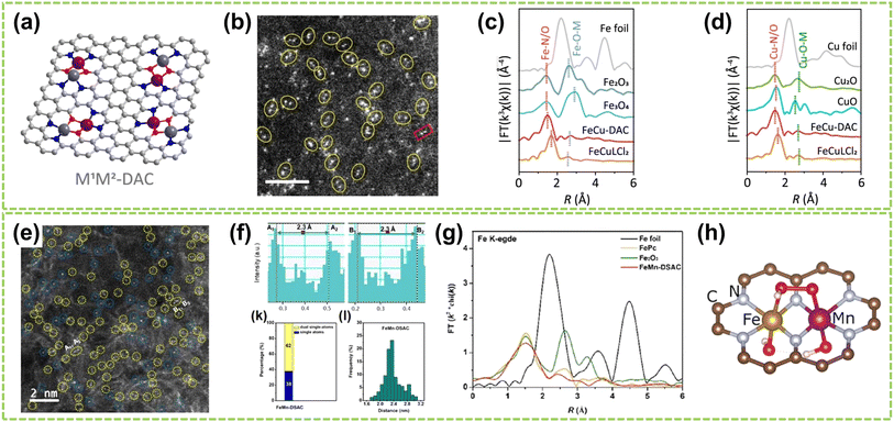 | ||
| Fig. 6 Structure characterization of heteronuclear DACs connected by heteroatomic bridges. (a) Schematic of the localized structure of the M1M2-DAC. (b) HAADF-STEM images of FeCu-DAC. The scale bar in panels is 2 nm. FT EXAFS spectra of (c) Fe K-edge and (d) Cu K-edge for FeCu-DAC and other references56 (reproduced with permission from ref. 56 copyright 2023, ACS). (e) AC HAADF-STEM images. The dotted circles in different colors show SAs (blue) or DSAs (yellow) in FeMn-DSAC. (f) Above: the corresponding Z-contrast analysis of regions A and B in (e). Below left: the statistical distribution of SAs and DSAs. Below right: statistical distribution of DSA distance. (g) FT of the k2-weighted EXAFS spectra at Fe K-edge. (h) Structure diagram of FeMn-DSAC57 (reproduced with permission from ref. 57 copyright 2022, John Wiley and Sons). | ||
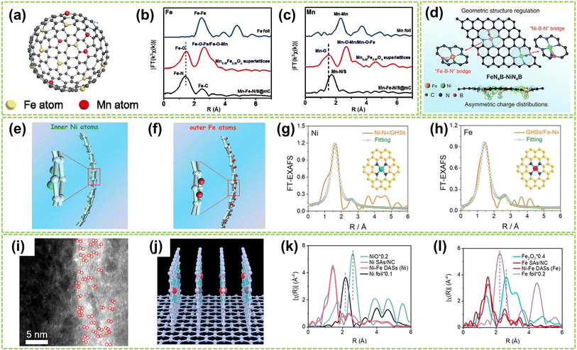 | ||
| Fig. 7 Structure characterization of heteronuclear DACs with isolated sites. (a) Schematic illustration of Mn–Fe–N/S@mC catalysts. (b) Fe and (c) Mn k3-weighted FT EXAFS curves of Mn–Fe–N/S@mC. The EXAFS curves of Mn0.43Fe2.57O4 supercrystals and metal foil are also included for comparison62 (reproduced with permission from ref. 61 copyright 2019, Elsevier). (d) Illustration of atomic configurations after the introduction of boron in the first coordinated sphere of Fe–Ni dual atoms63 (reproduced with permission from ref. 63 copyright 2024, John Wiley and Sons). Scheme of (e) the inner Ni atoms and (f) the outer Fe atoms. XAFS fitting curves of (g) Ni–N4/GHSs and (h) GHSs/Fe–N4 R space (insets in (g) and (h): atomic structure model of Ni–N4/GHSs and GHSs/Fe–N4, respectively)64 (reproduced with permission from ref. 64 copyright 2020, John Wiley and Sons). (i) AC HAADF-STEM image. The bright spots are highlighted by red circles. (j) Structural model of vertical graphene. FTs of k3-weighted (k) Ni K-edge and (l) Fe K-edge FT-EXAFS spectra of Ni–Fe DASs, Ni SAs, and the references65 (reproduced with permission from ref. 65 copyright 2023, ACS). | ||
In addition to the Fe-based DACs (particularly Fe–Ni DACs) with isolated sites, Co-based and Cu-based DACs have also been successfully synthesized and extensively studied in recent years. For instance, Li et al. fabricated a DAC composed of copper and cobalt atoms on a highly porous NC substrate (Cu–Co/NC).66 High-resolution AC HAADF-STEM imaging revealed paired bright spots, with slightly brighter Cu spots and darker Co spots, indicating the presence of heterogeneous dual-atom sites in Cu–Co/NC DAC, with an average interatomic distance of 0.53 nm (Fig. 8a). Besides, FT-EXAFS spectra exhibited prominent peaks at 1.44 Å and 1.45 Å for CoPc and Cu–Co/NC, respectively, indicating the existence of Co–N coordination. The absence of metal–metal and metal–O–metal coordination peaks in Cu–Co/NC suggests that Co and Cu sites are atomically dispersed within the catalyst (Fig. 8b and c). In addition, Jiao and co-workers clarified the synergistic interactionis between the dual active sites by synthesizing an asymmetric TeN2–CuN3 DAC.67 The formation of Te and Cu dual-atom sites was observed through HAADF-STEM image, where bright spots within red circles indicated the presence of dual-atom sites (Fig. 8d). Besides, clear identification of the dual-atom sites was achieved as shown in Fig. 8e, comprising approximately 78% of the total sites and the interatomic distance is approximately 0.33 nm. The significantly lower χ(R) intensity observed from the Te–N–C pathway compared to the Te–Te pathway confirms the atomically dispersed distribution of Te on the support (Fig. 8f). Fig. 8g further confirms the presence of Cu–Te by revealing a prominent peak at approximately 3.29 Å in the pair distribution function (PDF) Rietveld refinement results, corresponding to the Te–Cu pathway in TeN2–CuN3. Moreover, Yang et al. successfully synthesized Co/Ni–N-doped carbon catalysts by controlled pyrolysis of Co2+ and Ni2+-containing compounds within ZIF-8.68 As shown in Fig. 8h and i, the Co and Ni atoms are uniformly dispersed in CoN4–NiN4 pairs with an approximate spacing of 0.41 nm. Therefore, the theoretical models of neighboring CoN4 and NiN4 sites simulated by density functional theory (DFT) calculations were obtained and illustrated in Fig. 8j, including the interatomic spacing (0.41 nm) and metal coordination environment with a coordination number of approximately 4. Fig. 8k reveals the pronounced presence of Co/Ni–N peaks within the Co/Ni–NC, further confirming the coordination environment of CoN4–NiN4.
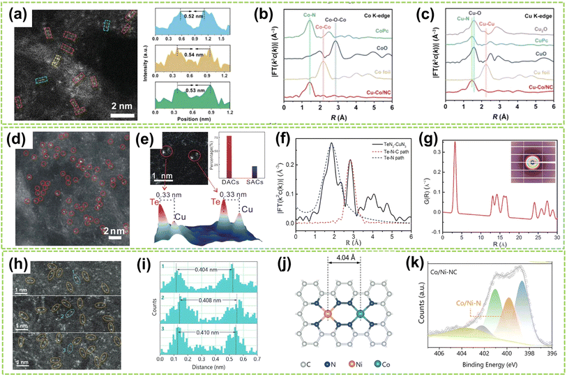 | ||
| Fig. 8 Structure characterization of heteronuclear DACs with isolated sites. (a) High-resolution AC HAADF-STEM image and the corresponding line-scanning intensity profiles. (b) Co K-edge and (c) Cu K-edge FT-EXAFS spectra of Cu–Co/NC and the references66 (reproduced with permission from ref. 66 copyright 2023, John Wiley and Sons). (d) HAADF-STEM image of TeN2–CuN3 DAC. (e) Above left: typical spot pairs for TeN2–CuN3 DAC. Above right: statistical analysis for double sites and single sites. Below: corresponding 3D intensity profiles of two pairs of DAC sites. (f) Fitting results for Te–N and Te–N–C paths of TeN2–CuN3 DAC. (g) PDF Rietveld refinement result for partial Cu–Te paths of TeN2–CuN3 DAC. Inset: the 2D scattering image of DAC67 (reproduced with permission from ref. 67 copyright 2023, Springer Nature). (h) AC HAADF-STEM images of Co/Ni–NC. (i) The corresponding diatomic distances are marked in (h). (j) Schematic model of neighboring CoN4 and NiN4 sites optimized by DFT calculations (the orange, green, blue, and gray spheres represent Ni, Co, N, and C atoms, respectively). (k) N 1s XPS spectra of Co/Ni–NC68 (reproduced with permission from ref. 68 copyright 2024, John Wiley and Sons). | ||
2.3 Molecular DACs
Molecular catalysts possess the advantages of structural controllability and uniformity of active sites, making it easier to enhance the reactivity and selectivity of products through chemical modifications.26,69,70 After Jasinski reported a cobalt phthalocyanine-based electrocatalyst in 1964, the transition metal-based M–N4 macrocyclic compounds have been found to have advantages such as the rich d-electron nature of transition metal centers and have now become one of the promising electrocatalysts.71 Recent studies have revealed that Co and Fe-coordinated porphyrins, phthalocyanines, corrins, and corroles possess highly active catalytic sites and exhibit great potential as non-precious metal catalysts for the water electrolysis reaction.72–74 DAMCs represent a class of molecular catalysts wherein two metal atoms serve as active centers. Compared to DACs, DAMCs provide the advantage of lower coordination numbers in carbon structure synthesis, significantly reducing the active site blockage.75 This section focuses primarily on the structure of DAMCs to better understand the composition and arrangement of dual-atom active sites in molecular catalysts, thereby elucidating the interactions between reactants and catalysts.For homonuclear DAMCs, Zhang and co-workers successfully prepared an ordered mesoporous catalyst with heterovalent metal pairs (HMP) sites CuII–CuI on a microporous MOF (as schematically shown in Fig. 9a).76 By controlling the distance between these sites (2.6 Å), avoiding the limitations imposed by micropores, thereby promoting the reaction. Besides, compared to the isovalent CuII–CuII sites, these Cu-HMP sites exhibited significantly improved expected yields. These findings provide important insights for future explorations of the performance of other HMP sites based on various MOFs. In another work, Zhang et al. synthesized two conjugated backbone dual-atom palladium complexes, BPB–Pd1 SAC and BPB–Pd2 DAC.77 Due to the π-conjugated backbone of BPB, BPB–Pd1 and BPB–Pd2 catalysts are immobilized onto carbon nanotubes through π–π stacking interactions, resulting in the formation of supported palladium complexes (Fig. 9b). Results and theoretical calculations indicate that the interaction between the dual-atom Pt species in BPB–Pd2 DAC leads to a higher FECO value. Besides, the electron effects generated between the sites reduce the free energy during the reaction process, thus facilitating the catalytic reaction. In another work, the construction of a heteroatom-bridged Fe dimer site (Fe–O–O–Fe) is achieved by utilizing the face-to-face self-assembly of iron phthalocyanine (FePc) molecules under microwave irradiation for molecular O2 adsorption.81
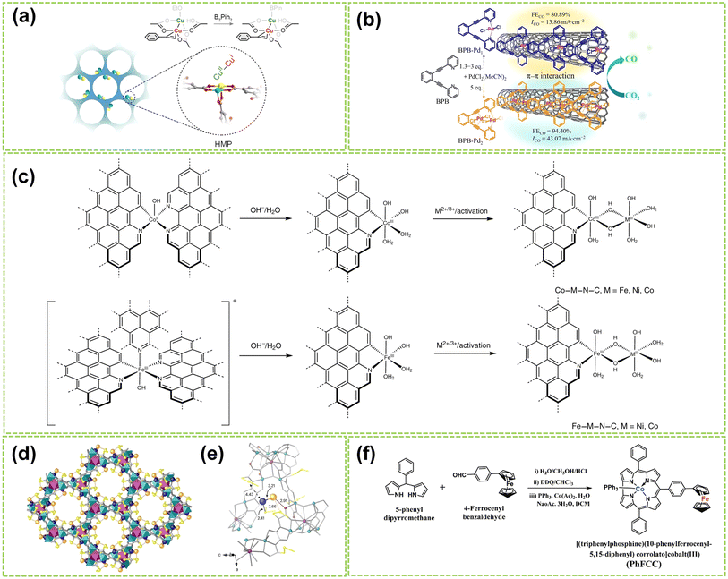 | ||
| Fig. 9 Structure illustration of molecular DACs. (a) Schematic diagram and structural formula of the heterovalent metal pair (HMP) site of copper. The color scheme for the atom: cyan for CuII, yellow for CuI, red for O, and gray for C76 (reproduced with permission from ref. 76 copyright 2024, ACS). (b) The preparation strategy for BPB–Pd1 and BPB–Pd2 and the electrocatalytic CO2 reduction performance of catalysts supported on carbon nanotubes77 (reproduced with permission from ref. 77 copyright 2024, Springer Nature). (c) A scheme showing the formation of DACs from the Co-based and Fe-based single-atom precatalysts. The dashed bonds connected to aromatic rings indicate extended N-doped carbon layers78 (reproduced with permission from ref. 78 copyright 2021, Springer Nature). (d) Formation of Pd1–Au1 dimers showing the structures of Pd1Au1@1 determined by SCXRD. Copper and strontium atoms from the network are represented by cyan and purple polyedra. Organic ligands are depicted as grey sticks and thioether groups as yellow sticks in all cases. Orange and blue spheres represent gold and palladium atoms, respectively, in Pd1–Au1 dimers. Blue, orange, and red dotted lines represent the Pd⋯S, Au⋯S, and Au⋯O interactions. (e) Details of X-ray crystal structure showing the main host–guest interactions and related structural parameters of Pd1–Au1 dimers79 (reproduced with permission from ref. 79 copyright 2024, Springer Nature). (f) Synthetic route for PhFCC80 (reproduced with permission from ref. 80 copyright 2021, John Wiley and Sons). | ||
Furthermore, Bai et al. developed a general synthesis method for N-doped carbon-loaded DACs using in situ electrochemical conversion of single-atom precatalysts under OER conditions.78 Six similar bimetallic catalysts containing Co, Fe, or Ni were synthesized by this method, and the synthesis process is displayed in Fig. 9f. This study reveals the formation of O–O bonds by nucleophilic attack on M(IV)![[double bond, length as m-dash]](https://www.rsc.org/images/entities/char_e001.gif) O with changes based on metal ions and coordination. Among these DACs, the Co–Fe–N–C and Ni–Fe–N–C catalysts exhibited high TOF values for OER in alkaline conditions, which are close to or higher than 1 s−1 at an overpotential of 300 mV. In addition, Ballesteros-Soberanas and co-workers prepared a uniform Pd1–Au1 heteronuclear DAMC using a highly stable, crystalline MOF as a nanoreactor.79 The precise atomic structure was revealed by single-crystal X-ray diffraction (SCXRD), as shown in Fig. 9c and d. The MOF's hexagonal channels (∼0.6 nm) contain the Pd1–Au1 dimer, stabilized by dimethyl sulfide chains. The Pd atoms are connected by 2.41 Å sulfur binding sites, while the Au atoms interact with MOF oxygen atoms and are weakly sulfur binding. Moreover, Samireddi et al. successfully synthesized a heteronuclear dual-metal complex (PhFCC) of Co and Fe using multi-walled carbon nanotubes (MWCNTs).80 As shown in Fig. 9e, the synthetic route of PhFCC involves the addition of phenyl groups, which extends the conjugated electron system and facilitates interactions with graphitic or electron-rich carbon supports.
O with changes based on metal ions and coordination. Among these DACs, the Co–Fe–N–C and Ni–Fe–N–C catalysts exhibited high TOF values for OER in alkaline conditions, which are close to or higher than 1 s−1 at an overpotential of 300 mV. In addition, Ballesteros-Soberanas and co-workers prepared a uniform Pd1–Au1 heteronuclear DAMC using a highly stable, crystalline MOF as a nanoreactor.79 The precise atomic structure was revealed by single-crystal X-ray diffraction (SCXRD), as shown in Fig. 9c and d. The MOF's hexagonal channels (∼0.6 nm) contain the Pd1–Au1 dimer, stabilized by dimethyl sulfide chains. The Pd atoms are connected by 2.41 Å sulfur binding sites, while the Au atoms interact with MOF oxygen atoms and are weakly sulfur binding. Moreover, Samireddi et al. successfully synthesized a heteronuclear dual-metal complex (PhFCC) of Co and Fe using multi-walled carbon nanotubes (MWCNTs).80 As shown in Fig. 9e, the synthetic route of PhFCC involves the addition of phenyl groups, which extends the conjugated electron system and facilitates interactions with graphitic or electron-rich carbon supports.
In conclusion, DACs consist of homonuclear or heteronuclear metal atoms as active sites exhibit varied intrinsic structures and chemical environments. Homonuclear DACs typically exhibit excellent single-reaction catalytic activity due to the similar electronic structures and adsorption properties around the metal atoms. In contrast, the heterogeneous structure of heteronuclear DACs endows them with the capability to possess high HER and OER bifunctional catalytic performances simultaneously. Furthermore, by rational designing of metal components and coordination environments of DACs, the energy barrier of the key reaction steps in water electrolysis would be reduced due to the synergistic effect between two adjacent metal sites, thus improving the catalytic activity, selectivity, and stability.
3. Microenvironment regulation of dual-atom site effect in DACs
DACs perform superior to SACs due to multiple adsorption sites and the unique site effects between active sites. Therefore, microenvironment regulation of the effects between dual-atom sites significantly enhances the catalytic activity, stability, and selectivity of DACs.7,42 This section comprehensively explains the mechanisms involved in the element, electronic, geometric, and coordination effects. It is worth noting that while the discussion has been categorized into four distinct aspects, these site effects generally work together in practical reactions, synergistically modulating the DAC microenvironment to enhance the catalyst's performance.3.1 Element effect
In DACs, the element effect can originate from three possible aspects: the interaction between the active metal centers, the incorporation of bridged heteroatoms, and the support atoms. Among them, the electronegativity of atoms affects the ability of central metal atoms to attract electrons, and higher electronegativity can lead to stronger adsorption of reactant molecules and intermediates, making it one of the critical factors in catalyst element selection.82,83 Consequently, the electronegativity differences between sites promote electron transfer, optimizing the electronic structures and adsorption configurations of DACs, affects reaction kinetics and selectivity, thereby exhibiting excellent electrocatalytic activity.For instance, Hao et al. conducted specialized research on interatomic electronegativity to demonstrate that shifts in electronegativity between Cu and Ni atoms result in significant electronic interactions in CuNi DAC.84 The electronegativity compensation effect of adjacent metal atoms in the synthesized CuN4–NiN4 catalyst promotes the formation of intermediates during the reaction process, thereby improving the activity and selectivity of the catalyst (Fig. 10a). Furthermore, they found that the significant decrease in activation energy (Ea) of CuN4–NiN4 (0.08 eV) promotes CuNi dual-atom sites on reaction kinetics. In another work, Tong and co-workers synthesized Cu/Zn–NC dual-metal atom dispersed catalysts composed of Cu–N4 and Zn–N4 species on N-doped carbon supports.88 Notably, the lower electronegativity of Zn atoms enables electron transfer to Cu atoms, facilitating O–O bond cleavage at the Cu–N4 active sites, significantly enhancing the catalyst's overall reactivity. Besides selecting appropriate dual-atoms by comparing their electronegativity, DFT calculation prior to experimental works also provides an effective approach for identifying the DACs with versatile metal active sites conducive to high-efficiency catalysis.85,86,89,90 For instance, Liu et al. employed DFT calculation to identify optimal dual-metal active sites for catalysis, comparing the predicted limit potential and potential-determining steps between Fe-based and Cu-based homo/heteronuclear DACs on C2N substrate.85 As shown in Fig. 10b, the elemental compositions of DACs significantly impact the catalytic reaction pathway, thereby influencing the selectivity of the catalyst. Furthermore, Jiao and co-workers also performed preliminary screening of Co–M (M = Fe, Cu, Zn) DACs based on carbon paper (CP) substrates using DFT calculations.86 As shown in Fig. 10c, a closer Gibbs free energy for H adsorption (ΔGH*) to zero under acidic and alkaline conditions indicates better hydrogen evolution performance. Experimental simulations of reaction mechanisms and comparison of relative free energies of intermediates confirmed the excellent HER activity of the prepared CoCu@CP DAC and CoFe@CP DAC under acidic and alkaline conditions, respectively (Fig. 10d and e). These results validate the ability of dual-atom centers to reduce the relative free energy effectively. Similarly, Liu et al. conducted DFT calculations to develop free energy profiles along the reaction pathway on Pt–Ru dimer structures and investigate the correlation between their activity of water-electrolysis reactions.90
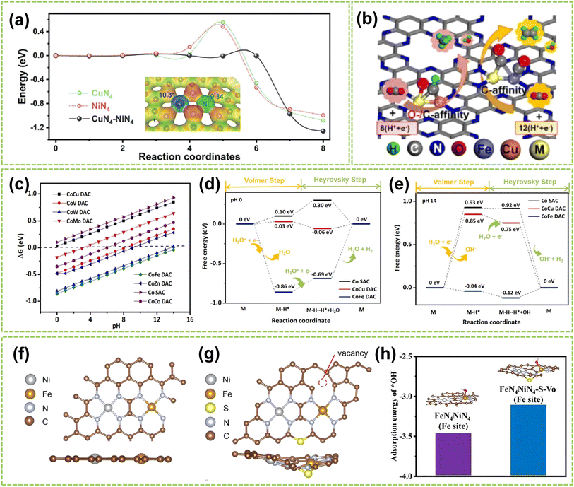 | ||
| Fig. 10 Element effect of DACs. (a) CI-NEB-calculated kinetic reaction processes, containing the energy variation in the initial, transition, and final states toward *COOH intermediate formation on NiN4, CuN4, and CuN4–NiN4. Inset: electronegativity compensation in the Cu–Ni dual atom site84 (reproduced with permission from ref. 84 copyright 2022, John Wiley and Sons). (b) Schematic illustration of DFT-optimized M2@C2N DACs performance85 (reproduced with permission from ref. 85 copyright 2021, Elsevier). (c) ΔGH* on Co SAC and different CoM DACs. Free energy diagram of CoCu DAC, CoFe DAC, and Co SAC under (d) acidic and (e) alkaline conditions, the “M” represents the CoCu DAC, CoFe DAC, and Co SAC, respectively86 (reproduced with permission from ref. 86 copyright 2023, Elsevier). The optimized structure of (f) FeN4NiN4 and (g) FeN4–NiN4–S–Vo (top view: above; side view: below). (h) The adsorption energy of *OH on FeN4–NiN4 and FeN4–NiN4–S–Vo87 (reproduced with permission from ref. 87 copyright 2021, Elsevier). | ||
Except for the interactions between metal atoms serving as active sites, the bridged heteroatoms doped in the dual-atom sites also induce similar elemental effects. Unlike the elemental metal–metal impact between different sites, the effects resulting from elements doping are typically metal–nonmetal elemental effects. Recently, researchers have modulated the electronic structure of dual-atom sites by doping with elements such as N, O, P, and S to regulate the microenvironment of DACs. Among them, doping N and O in graphite substrates to anchor metal sites is a common strategy to attain stabilization while ensuring the dispersion of atoms at the desired locations.16,91 Moreover, previous research suggests that introducing elements with relatively lower electronegative, such as S and P, offers a more precise approach to manipulating the electronic structure of dual-atom sites.92–95 For example, Zhang et al. doped S on defect-rich porous nitrogen and sulfur carbon frameworks (DNSC) co-anchored with Fe and Ni.87 The DFT-optimized structure is shown in Fig. 10f and g, showing that introducing S leads to forming carbon vacancies. This phenomenon increases the d-electron density of the Fe site at the Fermi energy level and leads to electron redistribution. Furthermore, Fig. 10h illustrates that the binding strength between the FeN4–NiN4–S–Vo sites and intermediates is relatively weak, enhancing its catalytic performance. These findings reveal that introducing heteroatoms and carbon vacancies exerts a crucial influence on the performance of DACs.96 Similarly, the study of Zhang and co-workers also validates that S doping in DACs enhances reaction kinetics.97 In conclusion, regulating the element effects between various atom sites is a crucial method for controlling the microenvironment of DACs. This approach governs the central atoms' intrinsic activity by coordinating various functional atoms. After that, the activity and stability of DACs are further enhanced through optimizing the adsorption of critical intermediates during the reaction process. Additionally, the electronic effects between sites and the coordination effect of support atoms are closely related to the elemental effects, which will be discussed in the following sections.
3.2 Electronic effect
In DACs, electronic effects are typically achieved through electron transfer between two adjacent metal atoms.17 This phenomenon can be interpreted as one metal center acting as the active site while the other is the electron regulator.16 In addition to electron transfer, the electronic effect also involves electron sharing and redistribution, impacting the electronic structure, charge distribution, and stability of reaction intermediates. These factors are crucial in regulating the microenvironment of DACs and affecting the catalytic process. Recently, Wang et al. successfully controlled the transformation from Co nanoparticles to Co2N5 dimers.40 As shown in Fig. 11a, Co2N5 dimers exhibit a significantly higher charge (1.11e) compare to other comparative catalysts. The experimental results confirm that the decrease in spin magnetic moment from nanoparticle to single-atom to dual-atom is primarily attributed to the redistribution of Co-3d orbital electrons due to level reordering, which weakens the adsorption of reaction intermediates and ultimately enhances the catalytic activity (Fig. 11b). In another work, Yang et al. synthesized Co/Ni–NC catalysts dispersed on an NC matrix.68 Through the analysis of the charge density difference between Ni and Co, clear electronic delocalization between the metals and neighboring N atoms can be observed (Fig. 11c). This electronic delocalization facilitates the adsorption of O2, thereby enhancing the catalytic activity. In addition, Fig. 11d compares the free energy of intermediates during OER. The relatively low adsorption energy of Co sites reveals that the Co sites in Co/Ni–NC serve as the active sites for the OER. In contrast, the NiN4 sites improve the reactivity of adjacent CoN4 active sites through electrostatic interactions. Consequently, electronic coupling between Co/Ni dimers can optimize the adsorption and desorption processes of atoms, molecules, and reaction intermediates, thereby enhancing the catalytic performance.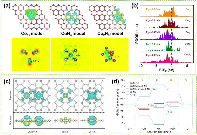 | ||
| Fig. 11 Electronic effect of DACs. (a) Charge density difference and Bader charge diagrams. (b) Projected density of states (PDOS)40 (reproduced with permission from ref. 40 copyright 2023, Springer Nature). (c) Charge density difference of Co/Ni–NC and the references (iso-surface = 0.008 a. u., yellow and blue regions represent electron accumulation and electron depletion, respectively). (d) Calculated ΔG (in eV) profiles for OER processes on catalysts under alkaline conditions at U = 1.23 V (ref. 68) (reproduced with permission from ref. 68 copyright 2024, John Wiley and Sons). | ||
Moreover, Gao's group loaded atomic Pd on α-Fe2O3(012) to construct unitary Pd–Fe pairs.98 As shown in Fig. 12a and b, an abundant delocalized charge accumulates along the Pd–Fe bonds, and the d-band of Fe closely matches that of Pd. These phenomena induce a strong electronic coupling in Pd–Fe pairs, which enhances the d-electron domination near the Fermi level and offers active sites for H2 adsorption and activation. In addition, Chen et al. designed a DAC composed of Co–Fe double sites (Co/Fe–SNC).99Fig. 12c–e illustrate the investigation of bonding and antibonding orbitals near the Fermi energy level. In Co/Fe–SNC, the Co and Fe SA sites exhibit electron-rich, highly electroactive regions absent in the other two SNCs, revealing a strong orbital coupling. In addition, Fig. 12f–h show the Co-3d orbitals displaying a distinct peak close to the Fermi level (EV = 0 eV) at an EV value of 0.33 eV, indicating their pronounced electrical activity in OER with a strong electron-depleting capability. The intense overlap between N-2p, C-2p, and S-3p orbitals also serves as electron-supplying centers, enabling efficient site-to-site electron transfer within Co/Fe–SNC. In another work, Wang et al. investigated N-doped graphene-supported (NGr) Ni–Fe DAC, with Ni acting as a nucleophilic center and Fe serving as an electrophilic center.100 It is attributed to substantial charge transfer occurring upon the binding of Fe and Ni metal atoms to the NGr surface, resulting in the difference in positive charges. Therefore, the positively charged Fe exhibits a significantly higher potential to Ni, ultimately achieving the regulation of catalytic performance.
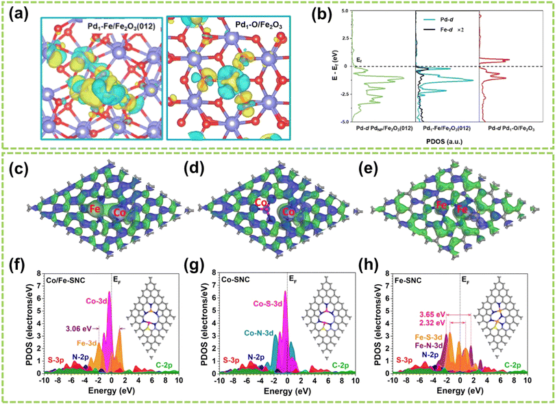 | ||
| Fig. 12 Electronic effect of DACs. (a) Differential charge density (cyan and yellow represent charge depletion and accumulation, respectively; the cutoff of the density-difference isosurface is 0.05 e Å−3). (b) PDOS for the total d orbitals of Pd and Fe98 (reproduced with permission from ref. 98 copyright 2022, ACS). 3D contour plot of bonding and anti-bonding orbitals near the Fermi level in (c) Co/Fe–SNC, (d) Co–SNC, and (e) Fe–SNC. Blue isosurface = bonding orbitals, and green isosurface = anti-bonding orbitals. PDOS of (f) Co/Fe–SNC, (g) Co–SNC, and (h) Fe–SNC. Pink balls = Co, orange balls = Fe, blue balls = N, yellow balls = S, and grey balls = C99 (reproduced with permission from ref. 99 copyright 2023, RSC). | ||
3.3 Geometric effect
Except for the two site effects mentioned above, the different geometric structures of sites in DACs also highly affect catalytic performance.101 Generally, the geometric effect functions from two aspects: the distance between active metal centers and the spatial positioning of these centers. By changing the distance between two active sites, the site distance effect is regulated, which will affect the adsorption of reactants, the process of electron transfer, and reaction kinetics, thereby impacting catalytic activity and selectivity. On the other hand, the spatial positioning effect of the active sites involves the arrangement of atoms and geometric configurations on the catalyst surface, which also significantly influence the reaction.The distance effect is achieved by modifying the spacing between dual metal atoms or incorporating non-coordinated atoms to fine-tune their separation from the central atom.102–104 For instance, Yao et al. investigated how the distance effect impacts the catalytic reaction performance of DACs by manipulating the spacing between the dual-metal atoms.103 They used dispersed NiCu–NC as an example to construct DAC models with four different site distances. Subsequently, DFT calculations then quantified the site distances and net electron difference, illustrating the electron redistribution effect. As depicted in Fig. 13a, the net electron difference gradually decreases as the distance widens, becoming trivial when the separation surpasses 5.0 Å, at which point the site distance effect is negligible. To prove this phenomenon, Chen et al.'s experiment showed that the site distance in DAC should be maintained within an appropriate range to ensure optimal catalytic activity.99 Statistical analysis was performed on 35 randomly selected metal species, and grating diagrams and intensity spectra were utilized to illustrate the presence of dual-atom sites (Fig. 13b and c) with a bond length of 3.479 Å. Furthermore, the distribution of distances between neighboring metal atoms in the DAC was determined in Fig. 13d. The results show that the predominant interatomic distances fall within the range of 3–6 Å, and atoms with distances exceeding 9 Å are considered isolated sites and no longer exhibit site distance effects.
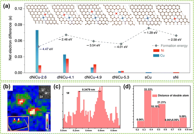 | ||
| Fig. 13 Site distance effect of DACs. (a) Net electron difference of Ni and Cu sites in different dNiCu models using sNi and sCu models as the baseline, respectively103 (reproduced with permission from ref. 103 copyright 2023, John Wiley and Sons). (b) The intensity profile of the dual-atom site. (c) Distance between two adjacent metal atoms. (d) Distance distribution of two adjacent metal atoms in dual-atom sites99 (reproduced with permission from ref. 99 copyright 2023, RSC). | ||
In addition to the distance effect between active dual metal centers, the spatial structural effect also plays a significant role in the performance of DACs.105 The spatial structure effect is influenced by the position, angles, and orientations of the active sites, which determine the adsorption pattern and orientation of reactants on the catalyst surface and further influence the strength and directionality of inter-site interactions. Consequently, precise modulation of these factors could enhance the performance of DAC and fine-tune the reaction rate and selectivity. For instance, Cepitis et al. compared SAs with three different spatially structured DACs and revealed the importance of the geometric effect in precise material design.106 Specifically, the fundamental SACs (Fig. 14a) is constrained by the OH–OOH scaling relationship,108 whereas the advanced DAC model (Fig. 14b) disrupts this scaling relationship while fail to reduce the overpotential.109Fig. 14c shows a different DAC model based on the dipyrrin structure, allowing for choosing reaction pathways and switching between scaling relationships. However, replicating such a precise model in an actual electrode would demand unfeasible atomic precision.110 Therefore, by shifting the research focus towards adjusting surface curvature, it was discovered that modifying surface curvature can alter the electronic structure and interatomic spacing (Fig. 14d). Four structures with different surface curvatures were established in Fig. 14e and f, and performance measurements were conducted using Co and Ni metals as models. It can be observed from Fig. 14g and h that the adsorption energy significantly decreases with increasing radius. Additionally, due to the increased number of simultaneously adsorbed intermediates, the decrease in the dissociation mechanism is more pronounced than that of the coupling mechanism (Fig. 14i and j). This study provides initial proof that surface curvature plays a crucial role in boosting catalyst performance, serving as an important direction for regulating bifunctional catalysts.
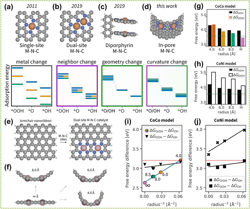 | ||
| Fig. 14 Spatial structural effect of DACs. Timeline of the M–N–C model development. The adsorption energies of intermediates vary with changing (a) M in the flat single-atom site model, (b) second M in the flat dual-atom site model, (c) geometry of the diporphyrin model, and (d) surface curvature of the in-pore model. Line color indicates a different M, line transparency indicates distinct geometry. (e) Top view on constructing a dual-atom site M–N–C model from an armchair nanoribbon. (f) Side view on curving the flat dual-atom M–N–C model into in-pore models. A periodic boundary condition was applied along the pore. (g) CoCo model energies, and (h) CoNi model energies. The green line indicates the ideal adsorption energy. (i and j) Linearized plot of free energy differences vs. the intersite distance, which is expressed as r−2. Using colored points as a reference, the pore radius of the CoCo model is respectively ∞, 8.5, 8.0, 6.0, and 4.0 Å from left to right107 (reproduced with permission from ref. 107 copyright 2023, ACS). | ||
Regarding the geometric effects on DACs, optimizing the catalyst's activity, selectivity, and stability can be achieved by adjusting site distances, coordination environment, spatial arrangement, etc. These adjustments provide practical strategies for achieving highly efficient catalytic performances.
3.4 Coordination effect
The coordination environment of DACs substantially impacts coordination effects, including the number of coordinating atoms at the active sites and the coordinated atoms that bonded to these sites.40,111,112 For instance, Hu et al. investigated the influence of atomic structures of active sites on the catalytic performance of Fe–Co–N–C by comparing their configurations with different active sites (including FeCoN6, FeCoN7, and FeCoN8) for ORR and OER.113Fig. 15a illustrates the optimized configurations of the Fe–Co–N–C models. The planar structure and negative Ef of these models indicate low strain and high stability. Notably, configurations with different atomic coordination environments exhibit significant differences in Ef. This is attributed to the enhanced stability of graphene-based materials achieved by increasing the coordination number of nitrogen atoms surrounding the metal atoms.114 These findings reveal that coordination numbers play a crucial role in determining the electronic configuration of metal atoms, which subsequently impacts catalytic performance. Consequently, establishing a well-defined coordination environment for the active metal center is paramount. By comparing the ηORR and ηOER of the active centers Fe and Co in Fe–Co–N–C, as shown in Fig. 15b and c, the Co atom exhibits superior catalytic activity for ORR and OER than the Fe atom. Therefore, the top position of the Co atom in Fe–Co–N–C serves as the primary active center for ORR and OER.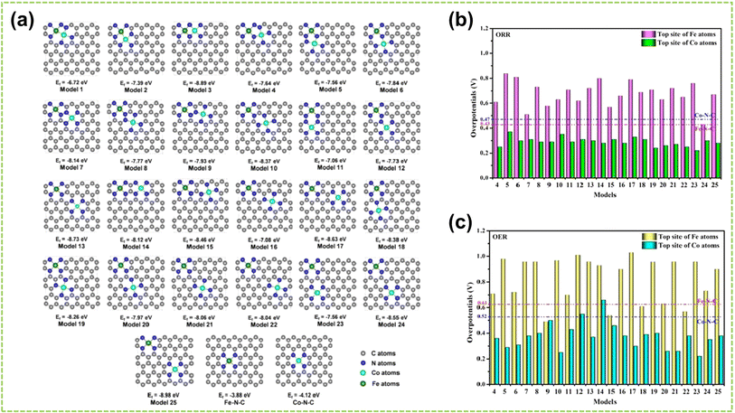 | ||
| Fig. 15 The coordination effect of DACs is caused by the coordination number. (a) The configurations and Ef of Fe–Co–N–C, Fe–N–C, and Co–N–C. The gray, blue, cyan, and green spheres indicate the C, N, Co, and Fe atoms, respectively. Summary of overpotentials for (b) ORR and (c) OER on Fe–Co–N–C at the U = 0 V. The corresponding overpotentials of Fe–N–C and Co–N–C are shown as the red and blue dashed lines, respectively113 (reproduced with permission from ref. 113 copyright 2020, Elsevier). | ||
The coordination effect between dual metal active sites can also be enhanced by altering the coordinated atoms from the support material that connects with these sites to improve the catalyst's activity and stability. Recently, Huang et al. studied SACs and DACs with various metal centers and coordination environments to determine the most stable cobalt DAC configuration.115 The structural models are shown in Fig. 16a. The results, depicted in the volcano plot of Fig. 16b, reveal the oxygen-bridged Co2N4O2 structure exhibits an optimal balance of activity and selectivity. PDOS analysis (Fig. 16c and d) shows the lower Co 3d orbital center (−2.95 eV) in Co2N4O2versus CoN4 (−0.98 eV), indicating the second metal can modulate the adsorption of intermediates by shifting the d-band center. In another work, Wang and co-workers investigated the most stable coordination configuration of DACs by studying boron-coordinated FeN4B–NiN4B models with different B and N positions.63 As shown in Fig. 16e and f, the analysis revealed that boron doping induces charge transfer and asymmetric charge distribution around the central Fe/Ni atoms. This optimizes the adsorption/desorption of intermediates in ORR/OER and reduces the activation energy of the potential-determining step. In addition to investigating the most stable coordination configurations of DACs, studying how to optimize their capabilities for multistep catalytic processes is crucial. For example, Wang et al. studied the asymmetric coordination of metal pairs.116 They synthesized atomically dispersed Fe–Se/NC and found the asymmetric Fe–Se coordination led to p–d orbital hybridization (Fig. 16g), resulting in asymmetric charge polarization. As depicted in Fig. 16h, this optimized electronic hybridization between Fe and Se improved the adsorption/desorption of intermediates. In another work, Tang et al. developed distinct anionic ligands for the two metals to construct Janus dual-metal sites to maximize DAC capabilities in multistep catalysis.117 They synthesized FeCo–N3O3@C catalysts, where Fe and Co are coordinated with N and O, respectively, acting as ORR and OER active sites (Fig. 16i). As shown in Fig. 16j, the charge density difference reveals a negative charge between the Fe and Co atoms, indicating bond formation and electron redistribution. The PDOS in Fig. 16k and l shows the higher charge density near the Fermi level for FeCo–N3O3@C versus single-atom references, accelerating electron transfer during the reactions.
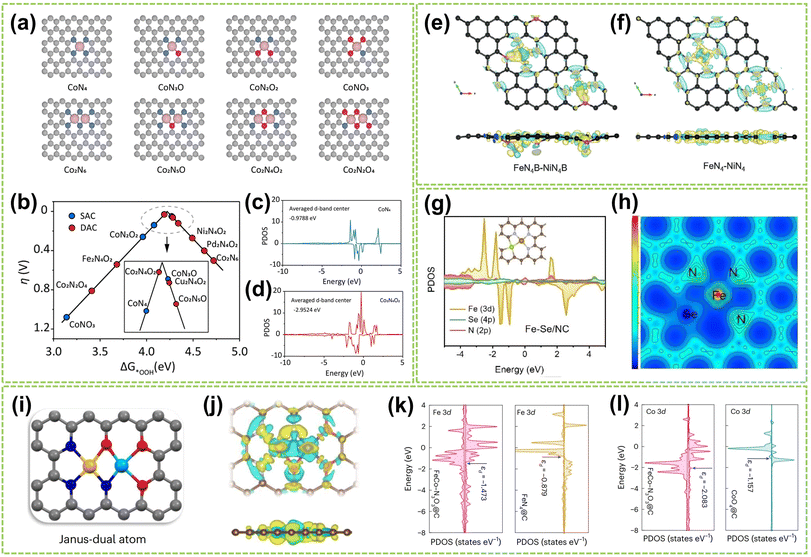 | ||
| Fig. 16 The coordination effect of DACs is caused by coordination atoms. (a) Different structure models are employed in the DFT calculations. (b) Calculated activity volcano plot for a two-electron ORR. PDOS and corresponding calculated d-band centers of Co 3d for (c) CoN4 and (d) Co2N4O2 models115 (reproduced with permission from ref. 115 copyright 2024, ACS). The differential charge density contour of (e) FeN4B–NiN4B and (f) FeN4–NiN4 (ref. 63) (reproduced with permission from ref. 63 copyright 2024, John Wiley and Sons). (g) The PDOS of Fe–Se/NC models. (h) The electron localization function analysis of Fe–Se/NC116 (reproduced with permission from ref. 116 copyright 2023, John Wiley and Sons). (i) The geometric structures of Janus dual-atom materials. In the ball-and-stick diagrams, the grey, blue, red, yellow, and cyan balls represent carbon, nitrogen, oxygen, iron and cobalt atoms, respectively. (j) Charge density differences for FeCo–N3O3@C. The yellow and cyan areas depict charge accumulation and depletion, respectively. The PDOS of (k) Fe 3d and (l) Co 3d for FeCo–N3O3@C, FeN4@C and CoO4@C117 (reproduced with permission from ref. 117 copyright 2024, Springer Nature). | ||
In conclusion, the microenvironment of DACs is regulated by the interplay of four key effects. Elemental effects involve metal–metal interactions, bridging heteroatoms, and support atoms, with electronegativity differences affecting adsorption and electron transfer. Closely related to this, electronic effects arise from electron transfer, sharing, and redistribution between the metal centers, impacting the electronic structure and stability of intermediates. Additionally, geometric effects function through site distances and spatial positioning, regulating adsorption, kinetics, and configurations. Lastly, coordination effects are determined by the number and identity of coordinating atoms, stabilizing the dual-atom site and modulating the electronic structure. Carefully engineering these microenvironment aspects allows researchers to maximize the synergistic dual-atom site effect and unlock the full catalytic potential of DACs for a wide range of reactions.
4. DACs for water electrolysis applications
Electrocatalytic water electrolysis has emerged as a highly efficient method for generating clean and pure hydrogen, encompassing the OER at the anode and the HER at the cathode. Considering the compatibility of the electrocatalysts in the same electrolyte for both HER and OER simultaneously, exploring highly efficient and stable bifunctional electrocatalysts toward overall water splitting is highly desirable. In recent years, DACs have shown remarkable advancements in electrochemical water electrolysis owing to their distinctive dual-atom site effects, offering a promising approach for overall water electrolysis. This chapter provides an overview of the recent progress of DACs in water electrolysis, commencing with a detailed mechanism discussion of half-reactions and followed by a thorough exploration of their performances across various pH environments.4.1 DACs for hydrogen evolution reaction (HER)
HER represents the cathodic half-reaction of water electrolysis and can be facilitated by active electrocatalysts to generate pure H2.118 HER typically involves a two-electron transfer process with few reaction steps,119 and numerous theoretical and experimental studies have revealed different HER pathways in acidic, alkaline, and neutral conditions:Alkaline/neutral condition:
| Volmer step: H2O + * + e− → OH− + H* | (1) |
| Heyrovsky step: H* + H2O + e− → OH− + H2 | (2) |
| Tafel step: 2H* → H2 + 2* | (3) |
Acidic condition:
| Volmer step: H+ + * + e− → H* | (4) |
| Heyrovsky step: H* + H+ + e− → H2 + * | (5) |
| Tafel step: 2H* → H2 + 2* | (6) |
In the above reaction steps, the H* represents the adsorbed hydrogen. The first step is the Volmer step (1) to produce H*, and subsequently, the reaction can proceed by the Heyrovsky step (2) and/or the Tafel step (3) to produce H2. The adsorption energy of H* on the active sites determines the selection of HER catalysts. Compared with acidic HER, the Volmer step in alkaline media requires proper adsorption of water molecules and additional energy to dissociate H2O, which complicates the production of H*. This indicates that many catalysts fail to dissociate water rapidly in the Volmer step.120 Consequently, overcoming the sluggish hydrogen kinetics poses a significant challenge in alkaline HER technology.121 Notably, by regulating the electronic effect between two different single atoms, heteronuclear DACs can accelerate HER better by efficiently providing dual sites for H* and/or OH* intermediates,105 positioning them among the most effective HER electrocatalysts available.122,123
In alkaline media, Chen et al. designed W–W dual-atom sites on P-doped carbon materials (W-AC) through a thermal migration strategy.124 The W-ACs, processing a platinum-like electronic structure, demonstrated excellent alkaline HER activity with an ultra-low overpotential of 53 mV at a current density of 10 mA cm−2 (η10) and a modest Tafel slope of 38 mV dec−1 (Fig. 17a), as well as good durability after 1000 CVs testing (Fig. 17b). Furthermore, by analyzing the kinetic barrier of the water dissociation step (Volmer step, ΔGH2O), the ΔGH2O value of W-ACs is significantly reduced (0.24 eV), indicating a markedly accelerated Volmer step (Fig. 17c). These W–W dual-atom sites exhibit a less negative H* adsorption energy and more favorable OH* desorption behavior compared to those in other counterparts, thereby enhancing its alkaline HER activity. In another study, Cai et al. synthesized Ir/Ru dizygotic single-atom sites on CoP catalysts (Ir/Ru DSACs) and investigated their performance in alkaline HER.125 As shown in Fig. 17d, IrRu DSACs exhibited a significantly higher average charge density variation than Ir and Ru SACs. It reveals a pronounced charge redistribution and the formation of a strong atomic local electric field caused by the electronic effect of IrRu DSACs. In situ Raman spectroscopy shows an increased stretching H2O vibration peak on IrRu DSACs, indicating an asymmetric adsorption configuration (H-down) structure during H2O adsorption (Fig. 17e). Consequently, IrRu DSACs facilitate interfacial water reorientation, promoting water dissociation through the electronic effects induced by a strong atomic electric field around the Ir and Ru sites, thereby enhancing alkaline HER activity (Fig. 17f).
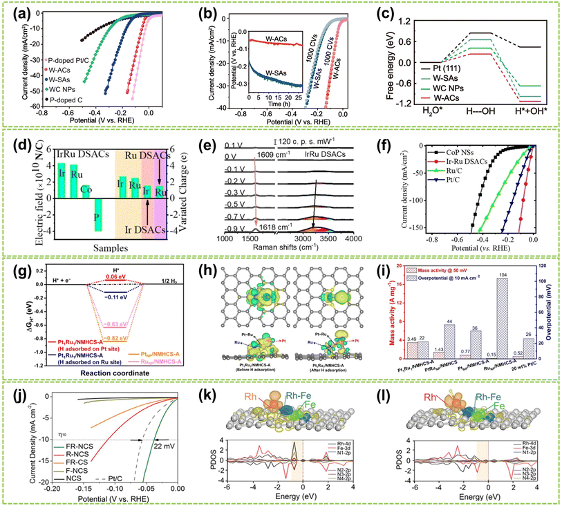 | ||
| Fig. 17 The HER performance of DACs in alkaline or acidic conditions. (a) Polarization linear sweep voltammetry (LSV) curves for W-ACs and reference catalysts in 1.0 M KOH solution. (b) LSV curves for W-SAs and W-ACs before and after 1000 CVs. Inset: the chronopotentiometry measurements at a current density of 10 mA cm−2. (c) The calculated free energy diagrams for water dissociation steps on W-ACs and the references124 (reproduced with permission from ref. 124 copyright 2022, Springer Nature). (d) Total electric field and charge variations of Ir–Ru pairs in IrRu DSACs. (e) The in situ Raman spectra of IrRu DSACs. (f) Electrochemical polarization curves of the as-prepared catalysts125 (reproduced with permission from ref. 125 copyright 2023, John Wiley and Sons). (g) Calculated ΔGH* values of different structures. (h) The charge density difference before and after adsorption of H on the Pt atom in the Pt1Ru1 dimer. (i) Mass activity and η10 of all samples tested in 0.5 M H2SO4 solution126 (reproduced with permission from ref. 126 copyright 2022, ACS). (j) Polarization curves of FR-NCS and reference samples. PDOS (k) before and (l) after H being adsorbed on the Rh atoms of FR-NCS with the corresponding charge distribution changes in the upper panels of each PDOS. Atomically dispersed Fe via the Rh–Fe bond retrieves some electrons in Rh to make the suitable number of active electrons in the Rh active site, facilitating a moderate value of ΔGH. The red, blue, and green areas correspond to the electron distributions in Rh, Rh–Fe bonding, and Fe atoms, respectively127 (reproduced with permission from ref. 127 copyright 2020, John Wiley and Sons). | ||
Compared to alkaline conditions, noble metal-based DACs have been investigated in acidic HER conditions mainly due to their strong anti-acid corrosion abilities. Notably, Pt-based catalysts demonstrate outstanding performance in the HER owing to the exceptional hydrogen binding energy of Pt–H bonds, leading to reduced overpotential, elevated exchange current density, and exceptional catalytic durability.128,129 Pt-based DACs are recognized as effective HER catalysts, as they offer a viable solution to circumvent the cost limitations associated with platinum metal.130–133 For example, Zhao et al. designed Pt1Ru1/NMHCS-A DAC for acidic HER. With hydrogen adsorbed on the Pt sites, this Pt1Ru1 exhibits the lowest |ΔGH*| value (Fig. 17g).126 Additionally, the difference in charge density of the Pt1Ru1 dimer reveals the electronic effect of Ru on Pt atoms (Fig. 17h), indicating that Pt atoms possess strong proton adsorption and reduction capabilities, thereby accelerating H2 generation and achieving optimal HER activity. As shown in Fig. 17i, Pt1Ru1/NMHCS-A shows high mass activity of 3.49 A mg−1@η50 and an ultra-low overpotential of 22 mV@η10, significantly surpassing those of the commercial 20 wt% Pt/C benchmark and its nanoparticle counterparts. In addition, Chao et al. fabricated Pd/Cu–Pt NRs consisting of Cu–Pt dual-atom sites on Pd nanoring (NRs).122 The Pd/Cu–Pt NRs possess atomically dispersed ultrafine structures and exhibit superior acidic HER performance compared to Pt/C, with an overpotential of only 22.8 mV at η10 and a Tafel slope of 25 mV dec−1. Da et al. synthesized a PtNi–NC catalyst by immobilizing PtNi on an NC substrate.134 Due to the electron effects between Pt and Ni atoms, PtNi-NC DAC exhibits excellent acidic HER catalytic activity. At a current density of 10 mA cm−2, it achieves an overpotential of 30 mV, comparable to commercial 20 wt% Pt/C catalysts.
Besides Pt, other noble metal-based DACs also show superior acidic HER performances. For instance, Zhou et al. employed a top-down approach to synthesize atomically dispersed catalysts containing Rh–Fe dual-metal sites.127 As shown in Fig. 17j, the Fe/Rh-anchored NC spheres (FR-NCS) demonstrated outstanding catalytic activity, exhibiting a positive shift in overpotential of 22 mV at η10 compared to commercial Pt/C catalysts. Fig. 17k and l illustrate the charge distribution to highlight the electron redistribution effect of Fe on Rh. When hydrogen is adsorbed, the electrons tend to cluster around the atomically dispersed Fe atoms (dark cyan region), while Rh atoms share electrons with the hydrogen species (red region). This charge redistribution phenomenon indicates that the Fe atoms in FR-NCS catalysts facilitate efficient charge distribution, while the Rh sites favor hydrogen adsorption and evolution. Consequently, the electronic effect between the dual-atom sites contributes to the exceptional acidic HER performance.
Considering the universality and versatility of DACs, it is crucial to develop DACs suitable for all pH HER. Employing DFT calculations to identify DACs with excellent HER performance under all pH conditions is a viable strategy. Recently, Jiao et al. systematically screened a series of highly active Co–M-DAC (M = Fe, Cu, Zn) DACs based on DFT calculations and experimental testing (Fig. 18a).86 The calculated ΔGH* values for hydrogen adsorption on these Co–M DACs were calculated, as shown in Fig. 18b. A ΔGH* value close to 0 eV indicates stronger hydrogen evolution capability, signifying higher HER performance. The CoCu DAC@CP exhibited enhanced HER activity (90 mV@η20) under 0.5 M H2SO4 conditions with a Tafel slope of 92.4 mV dec−1, suggesting a Volmer–Heyrovsky mechanism. In contrast, Co SAC@CP exhibited a more significant Tafel slope of 136.7 mV dec−1, indicating a Volmer mechanism (Fig. 18c and d). In contrast, under 1.0 M KOH, CoFe DAC@CP demonstrated superior HER activity (21.5 mV@η20) compared to other catalysts and exhibited a smaller Tafel slope of 62.9 mV dec−1 (Fig. 18e and f). This approach enables the pre-screening of relevant DACs, aiding in selecting optimal catalysts.
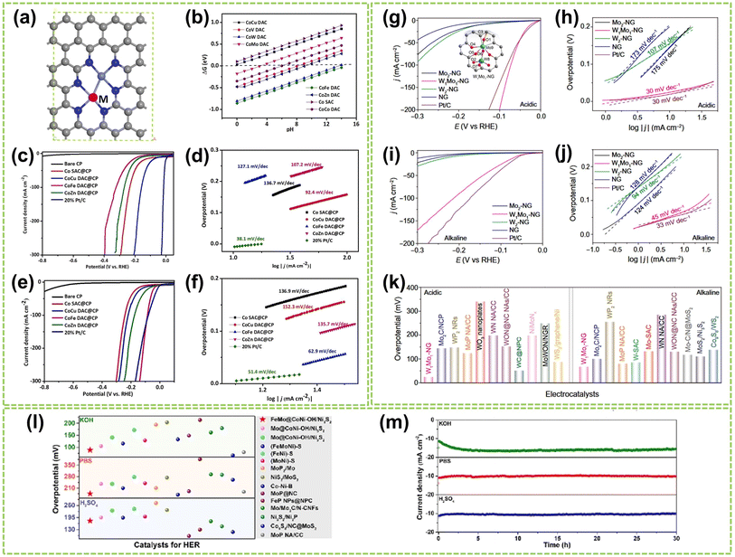 | ||
| Fig. 18 The HER performance of DACs in all pH conditions. (a) Structure diagram of CoM DACs, in which gray is C, dark blue is N, light blue is Co, and white is H; M = Cu, V, W, Mo, Fe, Zn, and Co. (b) ΔGH* on single Co atoms catalyst and different CoM DACs. (c) Polarization curves and (d) the corresponding Tafel plots of various catalysts in 0.5 M H2SO4. (e) Polarization curves and (f) the corresponding Tafel plots of different catalysts in 1.0 M KOH86 (reproduced with permission from ref. 86 copyright 2023, Elsevier). Polarization curves and the corresponding Tafel plots of W1Mo1–NG and reference samples in (g and h) 0.5 M H2SO4 and (i and j) 1.0 M KOH, respectively. Inset in (g) optimized geometries and possible active sites for H adsorption on W1Mo1–NG systems. Atom colors: cyan, Mo; royal blue, W; dark gray, C; blue, N; red, O; orange, H. (k) Comparison of the η10 in 0.5 M H2SO4 and 1.0 M KOH solutions for W1Mo1–NG and reported W- and Mo-based HER electrocatalysts135 (reproduced with permission from ref. 135 copyright 2020, AAAS). (l) The overpotential of FeMo@CoNi–OH/Ni3S2 at 10 mA cm−2 compared to other typical catalysts with HER properties in a wide pH range. (m) Chronopotentiometry measurements of FeMo@CoNi–OH/Ni3S2 in 1.0 M KOH, 1.0 M PBS, and 0.5 M H2SO4 solution136 (reproduced with permission from ref. 136 copyright 2023, Elsevier). | ||
Notably, several studies have confirmed that Mo-based materials exhibit excellent HER performance across all pH ranges. For instance, Yang et al. developed a novel O-coordinated W–Mo heterodimer (W1Mo1–NG) supported on nitrogen-doped graphene.135 This heterodimer possesses a unique W–O–Mo–O–C structure that influences the electron transfer between the catalyst and adsorbates (the inset in Fig. 18g), resulting in high HER performance of W1Mo1–NG under both acidic and alkaline conditions. As shown in Fig. 18g and h, W1Mo1–NG exhibits a significantly lower overpotential of 24 mV@η10 and a noticeably low Tafel slope of 30 mV dec−1 in acidic electrolytes. Furthermore, W1Mo1–NG exhibits outstanding HER performance (η10 = 67 mV) in alkaline electrolytes (Fig. 18i and j). Comparative analysis of overpotential values, as shown in Fig. 18k, reveals that the performance of W1Mo1–NG surpasses the reported Mo- and W-based catalysts under both acidic and alkaline conditions. In another work, Fang et al. synthesized rod-shaped Ni3S2 materials modified with single-atom Fe–Mo and encapsulated in nickel-based nanosheets (FeMo@CoNi–OH/Ni3S2).136 The introduction of Fe and Mo altered the electronic structure of the catalyst, leading to enhanced conductivity and improved HER performance. Under alkaline, acidic, and neutral conditions, FeMo@CoNi–OH/Ni3S2 exhibited excellent HER performance and remarkable stability over 30 hours, outperforming the majority of previously studied electrocatalysts (Fig. 18l and n). The modulation of electronic effects within the FeMo@CoNi–OH/Ni3S2 microenvironment results in significant electron redistribution, leading to a remarkable enhancement in catalytic performance. Shi et al. also developed a nitrogen-coordinated Ir–Mo DAC on a carbon matrix (Ir–Mo DAC/NC).137 The Ir–Mo DAC/NC demonstrated exceptional HER performance, with a significantly reduced HER overpotential of 11.3 mV and 23 mV@η10 in acidic and alkaline conditions, respectively. DFT calculations confirmed that the presence of Ir–Mo pair sites significantly enhanced the HER kinetics by facilitating the accumulation of electron density on the Ir–Mo sites.
4.2 DACs for oxygen evolution reaction (OER)
The OER is a kinetically sluggish process involving a four-electron and proton-coupled reaction, i.e., 2H2O → O2 + 4H+ + 4e−, which is the oxidation process and serves as the anodic half-reaction in water electrolysis. Therefore, the OER is the critical process that governs the overall efficiency of electrochemical water electrolysis.138–140 The reaction steps in both acidic and alkaline media are as follows:Alkaline conditions:
| OH− + * → OH* + e− | (7) |
| OH* + OH− → O* + H2O + e− | (8) |
| O* + OH− → OOH* + e− | (9) |
 | (10) |
 | (11) |
Acidic conditions:
| H2O + * → OH* + H+ + e− | (12) |
| OH* → O* + H+ + e− | (13) |
| O* + H2O → OOH* + H+ + e− | (14) |
 | (15) |
 | (16) |
The OER mechanism in both alkaline and acidic electrolytes includes a four steps process (outlined in formulae (7) to (16)), each step coupled with an electron transfer, and involves the formation of multiple intermediates (OH*, O*, OOH*, and  ) that ultimately lead to the production of oxygen gas (O2).141 Research on its reaction mechanism allows for the theoretical design of more efficient catalyst materials. Three distinct OER mechanisms have been identified: Adsorbate Evolution Mechanism (AEM), Lattice Oxygen Mechanism (LOM), and Oxide Path Mechanism (OPM).141–143 The AEM pathway is widely accepted in transition metal-based OER electrocatalysts, which involves four electron-proton transfer steps accompanied by metal oxidation and reduction. However, AEM is limited in explaining the origins of catalytic activity and, thereby, the mechanism observed in many highly active acidic OER catalysts. Alternatively, for LOM, lattice oxygen participates in the formation of O2 through direct O–O coupling, thereby surpassing the theoretical overpotential limit of the AEM.144 However, LOM leads to the formation of oxygen vacancies, accelerating the dissolution of metals and resulting in rapid catalyst deactivation.145 This phenomenon significantly affects the electrochemical stability of the catalyst. Recently, the OPM pathway, involving dual catalytic sites, facilitates direct coupling of O–O bond and the formation of O2 without the participation of lattice oxygen has recently gained significant attention.89,143,146 Studies have shown that OPM is typically more advantageous in dual-site systems, such as DACs.144,147 The differing binding strengths of intermediates on the two sites can minimize the maximum free energy. In contrast, the charge difference between the site atoms facilitates the formation of *O–O* coupling, ultimately leading to the generation of O2. These phenomena drive the transition of the OER pathway towards dual-site OPM, synergistically reducing the overpotential of OER and effectively enhancing its activity.
To elucidate the OER mechanism of optimal DACs, Fang et al. synthesized graphene-based heterogeneous DACs (M'M@NCs) as model catalysts to explore their OER activities and related *O–O* coupling mechanism at dual-metal sites (OPM pathway).89 A systematic exploration of 86 DAC systems (FeM, CoM, NiM, and CuM) along a preselected O–O coupling pathway, as shown in Fig. 19a, NiPd@NC (0.06 V), CuPd@NC (0.07 V), and CuPt@NC (0.08 V) outperform the conventional overpotential bottleneck of 0.37 V in AEM pathway. The preferred *OH adsorption on M2 dimers avoids the scaling issues between *OOH and OH, bringing η closer to 0 V. More importantly, by comparing the Gibbs free energy barriers of two competing reaction pathways (*OH → *OH–*OH vs. *OH → *O), the potential-determining step (PDS) for DACs primarily occurs through the coupling of *O–O* to generate *O2 (Fig. 19b–d). They further demonstrated that the synergistic effect between M2 dimers of selected M'M@NCs modifies the d-band center and M–O bond states, facilitating the moderate adsorption of *OH and enhancing OER activity via the *O–O* coupling mechanism. Moreover, the constant potential method (CPM) calculations reveal that OER activity on the diatomic catalysts is pH-dependent, suggesting that three selected DACs, i.e., NiPd@NC, CuPd@NC, and CuPt@NC, are effective under both acidic and alkaline conditions (Fig. 19e–g). Therefore, the *O–O* coupling mechanism is a crucial pathway for future OER research, presenting an alternative approach distinct from the traditional AEM pathway.
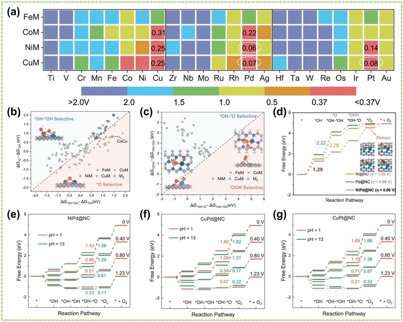 | ||
| Fig. 19 The OER performance of DACs in all pH conditions. (a) Activity map. The computed overpotential of the FeM, CoM, NiM, and CuM dimers on M′M@NC. (b) ΔG of *OH toward *OH–*OH versus *OH → *O + H+ + e−. Data points screened for high-performance homo- and hetero-nuclear catalysts are colored. (c) ΔG of *OH–*OH → *OH–*O + H+ + e−versus *OH–*OH → *OOH + H+ + e−. Insets: the schematic configuration of the different intermediates adsorbed on M′M@NC. The white, red, gray, and blue spheres in the atomic models represent H, O, C, and N atoms, respectively. (d) Free energy diagrams of NiPd@NC and the respective corresponding SACs for OER. Inset: the optimized configurations of oxygenated intermediates represented as NiPd@NC. Free energy diagrams of (e) NiPd@NC, (f) CuPd@NC, and (g) CuPt@NC at different potentials with pH = 1 and 13 and the corresponding ΔG*OH–*O→*O2 are labeled89 (reproduced with permission from ref. 89 copyright 2023, Springer Nature). | ||
Alkaline water electrolyzers, such as anion exchange membrane (AEM) electrolyzers, have been widely applied in industrial H2 production due to their relative simplicity and cost-effectiveness compared to other electrolyzers. In recent years, significant progress has been made in developing DACs that exhibit excellent OER activity and stability under alkaline conditions.55,93,119,148 Among them, Co-, Ni- and Fe-based catalysts have gained wide attention due to their excellent performance in OER.78,149 This is attributed to their ability to modulate the 3d electron configuration and spin state, the diversity of their crystal and electronic structures, as well as their natural abundance, making them promising alternatives to precious metal catalysts.150 Notably, Co- and Fe-based materials are widely utilized as OER electrocatalysts.151 For example, Zhang et al. synthesized Fe–Co DACs with both steric and planar structures, finding that the planar Fe–Co DACs show exceptional alkaline OER performance, with an overpotential of 190 mV@η10, a low Tafel slope of 33.6 mV dec−1 (Fig. 20a and b), and stability of exceeding 160 h.144 The planar Fe–Co dual-sites optimize the Co atom's electronic structure and electron transfer rates, thereby enhancing catalytic efficiency and highlighting the significance of microenvironmental regulation and its impact on the geometric effect in DACs. Surface-enhanced infrared spectroscopy was employed to identify the *O–O* bond that existed in both the planar-Fe–Co DAC and steric-Fe–Co DACs (Fig. 20c and d). As the voltage increased, peaks at 1470 cm−1 and 1468 cm−1 gradually appeared, corresponding to the *O–O* intermediates, intermediates preceding the release of O2. This observation confirms that the catalysts follow the OPM pathway during the OER process in an alkaline solution. In another work, Liu et al. synthesized adjacent Fe–Co DACS embedded in nitrogen-doped graphite carbon (FeCo-DACs/NC).152 As shown in Fig. 20e and f, FeCo-DACs/NC exhibited outstanding alkaline OER performance, achieving a low overpotential of 370 mV@η10 and a Tafel slope of 82.7 mV dec−1. They also investigated the distance effects in FeCo DACs by varying distances between two metal sites. By analyzing the free energy profiles and density of states (DOS) during the reaction process (Fig. 20g and h), the FeCo1 with the shortest metal distance exhibits optimal performance due to the lowest reaction-free energy and smallest band gap energy. This indicates that the enhanced electron conductivity in FeCo-DACs/NC not only facilitated electron transfer but also, through the synergistic interaction between the two metals, significantly impacted the rate-determining step (RDS) and reaction barriers for OER, thereby boosting the electrocatalytic process. Besides, He and co-workers also reported the Fe–Co dual-metal site catalyst through effective chemical doping and controlled thermal decomposition of ZIF-8, processing outstanding alkaline OER catalytic activity and stability.154
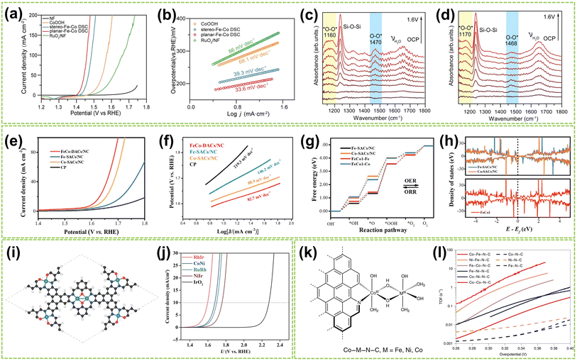 | ||
| Fig. 20 The OER performance of DACs in alkaline conditions. (a) Polarization curves and (b) Tafel slopes of stereo-Fe–Co DAC, planar-Fe–Co DAC, and reference samples. The measurements were conducted in 1.0 M KOH. In situ, FTIR spectra were recorded in the potential range of OCP to 1.6 V vs. RHE for (c) planar-Fe–Co DAC and (d) stereo-Fe–Co DAC144 (reproduced with permission from ref. 144 copyright 2024, Proceedings of the National Academy of Sciences). (e) LSV curves and (f) Tafel plots of FeCo–DACs/NC and references for OER. (g) Mechanism investigation of free energy diagrams for OER and ORR. (h) DOS patterns of FeCo1, Co–SACs/NC, and Fe–SACs/NC152 (reproduced with permission from ref. 152 copyright 2022, John Wiley and Sons). (i) Optimized geometric configurations of TM1TM2-COF. (j) Simulated polarization curves for RhIr–COF, CoNi–COF, RuRh–COF, and NiIr–COF in comparison with that of IrO2(110)153 (reproduced with permission from ref. 153 copyright 2022, Springer Nature). (k) The structure of Co-based single-atom precatalysts. (l) The activity of single-atom catalysts was obtained from the first LSV curve of these catalysts in Fe-free 1 M KOH78 (reproduced with permission from ref. 78 copyright 2021, Springer Nature). | ||
Except for Fe–Co DACs, some other DACs have outstanding alkaline OER performance. For instance, Wan and co-workers developed a dual-site NiFe catalyst on N-doped graphene nanosheets, achieving an overpotential of 270 mV at 10 mA cm−2 in the alkaline electrolyte.55 Similarly, atomically dispersed Ni/Co dual active sites anchored on NC hollow prisms (a-NiCo/NC) exhibit excellent alkaline OER performance.155 Zhou et al. constructed various homonuclear DACs (2TM-COF, which TM represents transition metal) and heteronuclear DACs (TM1TM2-COF) using two-dimensional (2D) COF materials as the substrate.153 As depicted in Fig. 20i, the stable geometry of the TM1TM2-COF features a metal dimer, where each TM atom is surrounded by two N atoms and two O atoms. Importantly, as shown in Fig. 20j, the lower OER starting potentials of RhIr–COF and CoNi–COF at 10 mA cm−2 further demonstrate the promise of these DACs for OER applications. Similarly, Bai and co-workers synthesized six N-doped carbon-supported DACs containing Co, Fe, or Ni.78 The structure of Co-based single-atom precatalysts is shown in Fig. 20k. These DACs were experimentally confirmed to exhibit excellent OER performance under alkaline conditions, with the Co–Fe–N–C and Ni–Fe–N–C catalysts achieving TOF values at the high end among known OER catalysts (Fig. 20l). This superior catalytic activity is attributed to the synergistic effect of the metal ions and their coordination environment, which facilitates nucleophilic attack on the M(IV)![[double bond, length as m-dash]](https://www.rsc.org/images/entities/char_e001.gif) O species and promotes the formation of O–O bonds.
O species and promotes the formation of O–O bonds.
Notably, the durability of OER catalyzed by DACs is a critical concern, especially when they are supported by carbon-based materials. Carbon-based supports are widely used due to their favorable surface structures for dispersed metal sites and excellent electron transport. However, carbon materials are susceptible to oxidative corrosion under OER conditions, particularly in acidic environments, leading to low catalyst stability.156,157 Besides, oxidative corrosion of the carbon support can cause the loaded active species to become detached or undergo structural collapse, leading to reduced catalyst stability.158 Strategies to address the durability challenge include nitrogen doping in the carbon support, using multilayer graphene, or exploring alternative corrosion-resistant and conductive supports to enhance the durability of atomically dispersed active sites under demanding OER conditions.46,136,159 A typical example is a series of methods proposed by Zoller et al. to increase the durability of carbon-based OER catalysts by using three-dimensional porous and multi-doped graphene-like structures as the best nanoform or by combining carbon with transition metal/oxide nanoparticles to produce synergistic effects.159
4.3 DACs for the overall water electrolysis
The overall reaction during electrochemical water electrolysis in an electrolytic cell is as follows:| Total reaction: H2O → H2 + ½O2 | (17) |
As discussed in the above sections on HER and OER, H2 is generated at the cathode and O2 at the anode during water electrolysis. Compared to single-function electrocatalysts, developing bifunctional catalysts that are efficient for both HER and OER presents significant challenges but also holds substantial potential for practical applications. DACs, with their unique dual-atom sites and associated site effects, are promising candidates for effective overall water electrolysis. This section reviews current strategies to boost the performance of bifunctional DACs in both HER and OER to improve their overall effectiveness in practical electrolysis applications.
Zhang and co-workers successfully synthesized a Pt@NiFeCo-E DAC with two types of Pt dual-atom structures, a 2Pt dimer with 2.6 Å interatomic distance and a Pt2 pair with 0.9 Å distance.32 The nickel-based hydroxide substrate was enriched with cationic vacancies, which served as anchoring sites for the Pt dual-atoms. The 2Pt dimer and Pt2 pair structures provided HER and OER bifunctional catalytic activity, respectively, resulting in excellent overall water splitting performance under alkaline conditions (14 mV@η10 for HER, 234 mV@100 mA cm−2 for OER, and 1719/1755 mV@100 mA cm−2 for overall water splitting in freshwater/seawater). This surpassed commercial Pt/C and most reported Pt-based catalysts. The catalyst also demonstrated robust long-term HER and OER stability over 96 hours. In another work, Wang et al. successfully generated Co2N5 dual atoms (Co2–N-HCS-900), exhibiting excellent alkaline OER (Fig. 21a) and HER (Fig. 21b) activities.40 The overpotentials achieved by the Co2–N-HCS-900-based system at current densities of 10, 100, and 200 mA cm−2 are competitive with commercial Pt/C + RuO2 (Fig. 21c). Besides, as shown in Fig. 21d, the Co2–N-HCS-900 potential remains constant after continuous operation for 1000 hours in 1.0 M KOH, demonstrating its exceptional stability. These results reveal the significant role of neighboring Co atoms in achieving enhanced bifunctional activity in the Co2N5 structure. In addition, due to the high intrinsic HER and OER activities of Mo-SACs162 and Fe-SACs,51,163 Chen et al. developed a Fe and Mo dual-site single-atom catalyst supported by CoNi–OH/Ni3S2 heterojunction, referred to as FeMo@CoNi–OH/Ni3S2.136 This bifunctional DAC exhibited outstanding OER (160 mV) and HER (89 mV) activities (Fig. 21e and f) and stability in alkaline conditions. When Mo serves as the active site, ΔGH* is negative and relatively small, indicating easy adsorption of H* and confirming Mo as the primary active site in the HER process (Fig. 21g). In addition, the ΔGH* approaches zero with the coexistence of Fe and Mo, suggesting that the synergistic effect between Fe and Mo enhances the HER performance. For OER, as shown in Fig. 21h, the reaction step of O* conversion to OOH* serves as the RDS and the ΔG for RDS (0.81 eV) is significantly lower than the ΔG for RDS of other reference catalysts, indicating that the site effect of Fe and Mo also enhances the OER performance. Recently, Zhao et al. employed a surface modification strategy to construct a Co/Ni DAC (CoNi–Ti3C2Tx) on MXene substrates.53 CoNi–Ti3C2Tx electrocatalysts exhibited excellent water-electrolysis performance in alkaline media, with overpotentials of 31 mV for HER and 241 mV for OER at 10 mA cm−2. Furthermore, CoNi–Ti3C2Tx electrocatalysts demonstrated high operational stability exceeding 100 hours at industrially relevant current densities of 500 mA cm−2 for both OER and HER. They use DFT calculations to reveal the d-band centers of CoNi–Ti3C2Tx are modulated by Co and Ni atoms, providing active adsorption sites and significantly enhancing the intrinsic activity of the electrocatalyst. In addition, the atomically dispersed Ru/Ni dual-atom sites, achieved by decorating Ru on a nickel vanadium layered double hydroxide (LDH) support, also exhibit excellent OER and HER performance under alkaline conditions.164
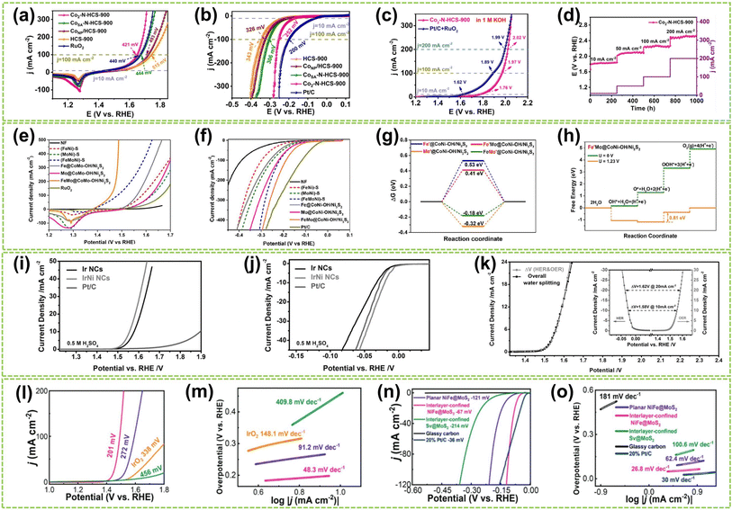 | ||
| Fig. 21 The overall water electrolysis performance of DACs in alkaline or acidic conditions. LSV curves toward (a) OER, (b) HER, and (c) overall water-electrolysis in 1.0 M KOH for all investigated and commercial (Pt/C or RuO2) catalysts. (d) Stability test for overall water electrolysis cells40 (reproduced with permission from ref. 40 copyright 2023, Springer Nature). (e) OER and (f) HER polarization curves of FeMo@CoNi–OH/Ni3S2 and reference samples with a scan rate of 5 mV s−1 in 1.0 M KOH solution. (g) ΔGH* on Fe′@CoNi–OH/Ni3S2, Mo′@CoNi–OH/Ni3S2, Fe′Mo@CoNi–OH/Ni3S2 and FeMo′@CoNi–OH/Ni3S2 reaction surfaces. (h) ΔG diagram on the Fe′Mo@CoNi–OH/Ni3S2 (ref. 136) (reproduced with permission from ref. 136 copyright 2023, Elsevier). Polarization curves of commercial Pt/C, Ir NCs, and IrNi NCs in 0.5 M H2SO4 for (i) OER and (j) HER. (k) Polarization curve for overall water electrolysis of IrNi NCs in a two-electrode configuration and the voltage difference between HER and OER. (Inset: polarization curves of IrNi NCs for HER and OER). All data are recorded at a scan rate of 5 mV s−1 without iR-compensation160 (reproduced with permission from ref. 160 copyright 2017, John Wiley and Sons). (l) Polarization curves and (m) Tafel plots of interlayer-confined NiFe@MoS2, planar NiFe@MoS2, interlayer-confined Sv@MoS2, and IrO2 for OER. (n) Polarization curves and (o) Tafel plots of interlayer-confined NiFe@MoS2, planar NiFe@MoS2, interlayer-confined Sv@MoS2, bare glassy carbon electrodes and 20% Pt/C for HER161 (reproduced with permission from ref. 161 copyright 2023, John Wiley and Sons). | ||
Acidic conditions offer a higher proton concentration and accelerate the water electrolysis process, making it crucial to develop highly efficient catalysts that can sustain both high catalytic activity and stability under such conditions. Since iridium oxide-based catalysts are the only commercial material that has demonstrated activity and stability for OER during long-term testing, this discussion particularly focuses on Ir-based DACs for acidic overall water electrolysis.160,165,166 For example, Pi et al. incorporated Ir as one of the metals in dual-atom sites to construct a series of carbon-supported, highly dispersed IrM (M = Ni, Co, Fe) nanoclusters (NCs) electrocatalysts.160 The polarization curves of the catalysts in 0.5 M H2SO4 indicated that IrNi NCs exhibited the best catalytic activity for both OER (Fig. 21i) and HER (Fig. 21j). Consequently, IrNi nanomaterials were employed as both cathode and anode catalysts in a dual-electrode water electrolysis system, with the polarization curves shown in Fig. 21k. The voltage difference (ΔV) between the two half-reactions (HER and OER) was calculated based on the principle of charge conservation for comparison, demonstrating alignment with the overall water-electrolysis polarization curve of IrNi NCs and indicating a steady-state process. Recent findings suggest that confining metal dual-atoms within the van der Waals gaps of two-dimensional layered materials can significantly improve the kinetics and reduce the energy requirements of catalytic reactions.167,168 Jiang et al. synthesized a unique type of NiFe@MoS2 DACs by assembling Ni and Fe dual-atoms into the interlayer of MoS2 nanosheets.161 This distinctive interlayer confinement structure protects the metal dual-atoms, preventing their aggregation and deactivation during prolonged reactions in harsh acidic conditions, thereby sustaining the catalyst's activity over time. Fig. 21l–o evaluates the electrochemical performance of the catalyst in a 0.5 M H2SO4 solution and confirms that the interlayer-enclosed NiFe@MoS2 exhibits higher catalytic activity for HER and OER compared to unconstrained NiFe@MoS2, as evidenced by the Tafel slopes and overpotentials. Due to its simple synthesis method and wide applicability, this unique and effective structure is expected to advance the research on DAC synthesis under acidic conditions.
In another work, Rong et al. developed an atomically dispersed Ru–Co dual-site catalyst that modulated the affinity of intermediates on the Ru surface, enabling a highly active bifunctional catalyst for water splitting under both acidic and basic conditions.169 As shown in Fig. 22g, the Ru/Co–N–C-800 °C catalyst exhibited low OER overpotentials of 232 and 276 mV in 0.5 M H2SO4 and 1 M KOH, respectively, along with a high TOF of 9.20 s−1 at 1.53 V and excellent durability over 20 hours of operation in both environments. Furthermore, the catalyst demonstrated superior HER activity, requiring only 17 mV and 19 mV overpotential to deliver 10 mA cm−2 in 0.5 M H2SO4 and 1 M KOH, respectively, even outperforming commercial Pt/C (Fig. 22h).
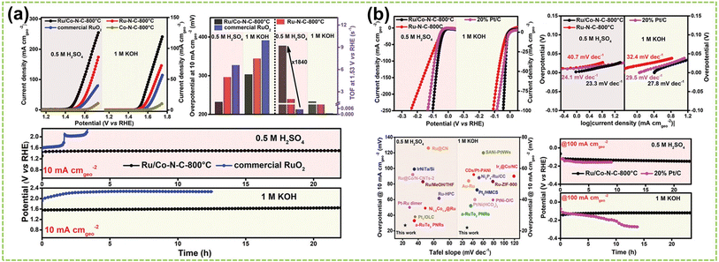 | ||
| Fig. 22 The overall water electrolysis performance of DACs in wide-pH conditions. (a) Electrocatalytic OER performance of Ru/Co–N–C-800 °C compared with other samples. Above left: OER polarization curves were obtained at a scan rate of 5 mV s−1 in N2-saturated 0.5 M H2SO4 and 1 M KOH. Above right: comparison of overpotential to achieve a current density of 10 mA cm−2 and TOF value at 1.53 V versus RHE in 0.5 M H2SO4 and 1 M KOH. Below: the chronopotentiometry of Ru/Co–N–C-800 °C and commercial RuO2 in 0.5 M H2SO4 and 1 M KOH. (b) Electrocatalytic HER performance of Ru/Co–N–C-800 °C compared with other samples. Above left: HER polarization curves obtained at a scan rate of 5 mV s−1 in N2-saturated 0.5 M H2SO4 and 1 M KOH. Above right: the corresponding Tafel plots in 0.5 M H2SO4 and 1 M KOH. Below left: comparison of overpotential at 10 mA cm−2 and Tafel slope with previously reported HER catalysts in acid and alkaline conditions. Below right: the chronopotentiometry curves of Ru/Co–N–C-800 °C and commercial Pt/C in 0.5 M H2SO4 and 1 M KOH169 (reproduced with permission from ref. 169 copyright 2022, John Wiley and Sons). | ||
5. Summary and perspective
Developing highly efficient catalysts for electrochemical water electrolysis has been a pivotal research aspect of producing high-purity hydrogen. In recent years, DACs, featured with two specifically active metal centers arranged in a specific configuration on support, have garnered significant attention as efficient catalysts towards HER, OER, and overall water electrolysis. Notably, DACs provide dual-atom sites that overcome the shortages of SACs, such as limited adsorption modes and relatively low reaction activity, while retaining the advantages of SACs, including unsaturated coordination structures, high metal utilization, and relatively homogeneous active sites. Microenvironment regulation plays a vital role in fully utilizing and maximizing the dual-atom site effects in DACs. In this review, we first classified DACs into three categories, i.e., homonuclear, heteronuclear, and molecular configurations, based on their different dual-atom configurations, coordination numbers, and support structures. We then summarize the microenvironment regulation in DACs, focusing on the elemental, electronic, geometric, and coordination effects between the two metal atom sites. These factors distinguish DACs from other catalysts and significantly enhance their catalytic reactivity and stability. The review also highlights recent contributions of DACs to HER, OER, and overall water electrolysis under different pH conditions, particularly emphasizing the microenvironment regulation of the dual-atom site effects on DACs for promoting water electrolysis. While there have been exciting developments in DACs, challenges remain in optimizing their syntheses, characterizations, and applications.(1) Optimal selection of metal atom species and support materials is essential to catalyze specific reactions. This necessitates a comprehensive understanding of the complex interactions among metal atoms, as well as between atoms and supports. Such understanding is crucial in determining the catalytic performance, ensuring that these interactions mutually enhance reactivity. Besides, support materials with larger surface areas improve the catalytic selectivity and activity, while they may also possess irregular cavities or defects that potentially disrupt site equilibrium.
(2) Achieving a uniform distribution of diatomic sites remains a significant challenge. Many reported diatomic catalysts (DACs) fail to exhibit the anticipated uniform distribution of active sites, primarily due to their random spatial arrangement. This randomness can lead to aggregation or migration of active metal species, undermining their effectiveness. To address these issues, it is essential to develop and refine synthesis methods that consistently yield well-dispersed DACs.
(3) In situ characterization is necessary for understanding the properties of active sites, but it has certain limitations. The state of active sites is influenced by various factors such as adsorbates, current density, and high potentials. However, in most studies, powerful characterization techniques are typically employed in a non-in situ manner, such as XPS, HAADF-STEM, and XAFS. Although theoretical approaches like DFT calculations and simulations can provide theoretical insights, a significant disparity exists between theoretical understanding and practical application, making it challenging to fully comprehend the structure and composition of catalysts at the atomic scale. Therefore, suitable in situ characterization techniques for DACs are urgently needed.
(4) Sustaining the stability of DACs presents a significant challenge. The metal atoms within DACs are vulnerable to environmental conditions, including aggregation or deactivation of active sites in acidic environments and deactivation at high temperatures. These factors considerably impact both the catalytic activity and stability of DACs, thereby restricting their long-term applicability and recyclability.
In conclusion, this review aims to provide a comprehensive insight into DACs applied for water electrolysis. We summarized the advancements in categorizing DACs, examined how regulating their microenvironment influences their properties, focused on the dual-atom site effect, and discussed their advanced applications in electrochemical water electrolysis. Despite facing challenges such as exploring the diversity of supports, precisely characterizing and modulating active structures, and fulfilling the requirements for large-scale practical applications, DACs present a promising avenue for exploring high-performance catalysts at the atomic level. Moreover, studying microenvironment regulation in DACs for water electrolysis can also provide references and guidance for other electrochemical applications.
Data availability
Data availability does not apply to this article as no new data were created or analyzed in this study.Author contributions
X. R. and S. R. contributed equally to this work, which involved writing, editing, and finalizing the manuscript. G. J. conceived this work and co-wrote the manuscript. X. H. Q., X. G. and G. J. revised the manuscript. All authors read and approved the final manuscript.Conflicts of interest
There are no conflicts of interest to declare.Acknowledgements
This work is supported by the Strategic Hiring Scheme of The Hong Kong Polytechnic University (No. P0047728), and GuangDong Basic and Applied Basic Research Foundation (No. 2023A1515110259).References
- M. Chatenet, B. G. Pollet, D. R. Dekel, F. Dionigi, J. Deseure, P. Millet, R. D. Braatz, M. Z. Bazant, M. Eikerling, I. Staffell, P. Balcombe, Y. Shao-Horn and H. Schäfer, Chem. Soc. Rev., 2022, 51, 4583–4762 RSC.
- K. Kohse-Hoeinghaus, Chem. Rev., 2023, 123, 5139–5219 CrossRef CAS PubMed.
- V. H. Do and J. M. Lee, Chem. Soc. Rev., 2024, 53, 2693–2737 RSC.
- H. Nishiyama, T. Yamada, M. Nakabayashi, Y. Maehara, M. Yamaguchi, Y. Kuromiya, Y. Nagatsuma, H. Tokudome, S. Akiyama, T. Watanabe, R. Narushima, S. Okunaka, N. Shibata, T. Takata, T. Hisatomi and K. Domen, Nature, 2021, 598, 304–307 CrossRef CAS PubMed.
- D. Zhao, Z. W. Zhuang, X. Cao, C. Zhang, Q. Peng, C. Chen and Y. D. Li, Chem. Soc. Rev., 2020, 49, 2215–2264 RSC.
- Y. Wang, D. S. Wang and Y. D. Li, Adv. Mater., 2021, 33, 2008151 CrossRef CAS PubMed.
- W. Y. Zhang, Y. G. Chao, W. S. Zhang, J. H. Zhou, F. Lv, K. Wang, F. X. Lin, H. Luo, J. Li, M. P. Tong, E. K. Wang and S. J. Guo, Adv. Mater., 2021, 33, 2102576 CrossRef CAS.
- X. Sun, S. Wang, Y. Hou, X. F. Lu, J. Zhang and X. Wang, J. Mater. Chem. A, 2023, 11, 13089–13106 RSC.
- C. C. Hou, H. F. Wang, C. X. Li and Q. Xu, Energy Environ. Sci., 2020, 13, 1658–1693 RSC.
- T. C. Pu, J. Q. Ding, F. X. Zhang, K. Wang, N. Cao, E. J. M. Hensen and P. F. Xie, Angew. Chem., Int. Ed., 2023, 62, e202305964 CrossRef CAS PubMed.
- W. T. Jing, H. Shen, R. X. Qin, Q. Y. Wu, K. L. Liu and N. F. Zheng, Chem. Rev., 2023, 123, 5948–6002 CrossRef CAS PubMed.
- Y. Chen, J. Lin, B. H. Jia, X. D. Wang, S. Y. Jiang and T. Y. Ma, Adv. Mater., 2022, 34, 2201796 CrossRef CAS PubMed.
- Y. X. Wang, X. Z. Cui, J. Q. Zhang, J. L. Qiao, H. T. Huang, J. L. Shi and G. X. Wang, Prog. Mater. Sci., 2022, 128, 100964 CrossRef CAS.
- W. Y. Zhang, S. Y. Yi, Y. H. Yu, H. Liu, A. Kucernak, J. Wu and S. Li, J. Mater. Chem. A, 2023, 12, 87–112 RSC.
- J. J. Ge, Z. J. Li, X. Hong and Y. D. Li, Chem. - Eur. J., 2019, 25, 5113–5127 CrossRef CAS PubMed.
- L. B. Li, K. Yuan and Y. W. Chen, Acc. Mater. Res., 2022, 3, 584–596 CrossRef CAS.
- Y. F. Hu, Z. S. Li, B. L. Li and C. L. Yu, Small, 2022, 18, 2203589 CrossRef CAS PubMed.
- G. Rocha, M. A. R. da Silva, A. Rogolino, G. A. A. Diab, L. F. G. Noleto, M. Antonietti and I. F. Teixeira, Chem. Soc. Rev., 2023, 52, 4878–4932 RSC.
- T. M. Tang, Z. L. Wang and J. Q. Guan, Coord. Chem. Rev., 2023, 492, 215288 CrossRef CAS.
- L. C. Liu and A. Corma, Chem. Rev., 2023, 123, 4855–4933 CrossRef CAS PubMed.
- A. Pedersen, J. Barrio, A. L. Li, R. Jervis, D. J. L. Brett, M. M. Titirici and I. E. L. Stephens, Adv. Energy Mater., 2022, 12, 2102715 CrossRef CAS.
- M. Balamurugan, H. Y. Jeong, V. S. K. Choutipalli, J. S. Hong, H. Seo, N. Saravanan, J. H. Jang, K. G. Lee, Y. H. Lee, S. W. Im, V. Subramanian, S. H. Kim and K. T. Nam, Small, 2020, 16, 2000955 CrossRef CAS PubMed.
- J. Q. Shan, C. Ye, Y. L. Jiang, M. Jaroniec, Y. Zheng and S. Z. Qiao, Sci. Adv., 2022, 8, eabo0762 CrossRef CAS PubMed.
- Y. F. Zhao, H. Zhou, X. R. Zhu, Y. T. Qu, C. Xiong, Z. G. Xue, Q. W. Zhang, X. K. Liu, F. Y. Zhou, X. M. Mou, W. Y. Wang, M. Chen, Y. Xiong, X. G. Lin, Y. Lin, W. X. Chen, H. J. Wane, Z. Jiang, L. R. Zheng, T. Yao, J. C. Dong, S. Q. Wei, W. X. Huang, L. Gu, J. Luo, Y. F. Li and Y. E. Wu, Nat. Catal., 2021, 4, 134–143 CrossRef CAS.
- X. Hai, Y. Zheng, Q. Yu, N. Guo, S. B. Xi, X. X. Zhao, S. Mitchell, X. H. Luo, V. Tulus, M. Wang, X. Y. Sheng, L. B. Ren, X. D. Long, J. Li, P. He, H. H. Lin, Y. G. Cui, X. N. Peng, J. W. Shi, J. Wu, C. Zhang, R. Q. Zou, G. Guillén-Gosálbez, J. Pérez-Ramírez, M. J. Koh, Y. Zhu, J. Li and J. Lu, Nature, 2023, 622, 754–760 CrossRef CAS PubMed.
- Y. Gao, B. Z. Liu and D. S. Wang, Adv. Mater., 2023, 35, 2209654 CrossRef CAS PubMed.
- J. X. Wang, D. N. Deng, Q. M. Wu, M. J. Liu, Y. C. Wang, J. B. Jiang, X. R. Zheng, H. R. Zheng, Y. Bai, Y. B. Chen, X. Xiong and Y. P. Lei, ACS Nano, 2023, 17, 18688–18705 CrossRef CAS PubMed.
- X. N. Li, L. H. Liu, X. Y. Ren, J. J. Gao, Y. Q. Huang and B. Liu, Sci. Adv., 2020, 6, eabb6833 CrossRef CAS PubMed.
- Y. Chen, J. Lin, Q. Pan, X. Liu, T. Y. Ma and X. D. Wang, Angew. Chem., 2023, 135, e202306469 CrossRef.
- Y. J. Sa and S. H. Joo, Chem, 2019, 5, 3006–3007 CAS.
- J. M. Wang, E. Kim, D. P. Kumar, A. P. Rangappa, Y. Kim, Y. X. Zhang and T. K. Kim, Angew. Chem., 2022, 134, e202113044 CrossRef.
- P. Zhang, M. Gan, Y. Song, P. Liu, H. Liang, Y. Shen, B. Xu, T. Liao, J. Guo and Z. Sun, Appl. Catal., B, 2024, 355, 124214 CrossRef CAS.
- Q. Hao, H. X. Zhong, J. Z. Wang, K. H. Liu, J. M. Yan, Z. H. Ren, N. Zhou, X. Zhao, H. Zhang, D. X. Liu, X. Liu, L. W. Chen, J. Luo and X. B. Zhang, Nat. Synth., 2022, 1, 719–728 CrossRef.
- Y. S. Wei, L. M. Sun, M. Wang, J. H. Hong, L. L. Zou, H. W. Liu, Y. Wang, M. Zhang, Z. Liu, Y. W. Li, S. Horike, K. Suenaga and Q. Xu, Angew. Chem., Int. Ed., 2020, 59, 16013–16022 CrossRef CAS.
- N. Q. Zhang, X. X. Zhang, Y. K. Kang, C. L. Ye, R. Jin, H. Yan, R. Lin, J. R. Yang, Q. Xu, Y. Wang, Q. H. Zhang, L. Gu, L. C. Liu, W. Y. Song, J. Liu, D. S. Wang and Y. D. Li, Angew. Chem., 2021, 133, 13500–13505 CrossRef.
- T. M. Tang, X. Bai, Z. L. Wang and J. Q. Guan, Chem. Sci., 2024, 15, 5082–5112 RSC.
- W. J. Zou, R. H. Lu, X. L. Liu, G. F. Xiao, X. B. Liao, Z. Y. Wang and Y. Zhao, J. Mater. Chem. A, 2022, 10, 9150–9160 RSC.
- H. M. Chen, Y. Yang, C. Jiao, Z. W. Zhuo, J. J. Mao and Y. Liu, Nano Res., 2023, 17, 3413–3422 CrossRef.
- F. F. Xu, B. Feng, Z. Shen, Y. Q. Chen, L. Jiao, Y. Zhang, J. Y. Tian, J. R. Zhang, X. Z. Wang, L. J. Yang, Q. Wu and Z. Hu, J. Am. Chem. Soc., 2024, 146, 9365–9374 CrossRef CAS PubMed.
- X. K. Wang, L. L. Xu, C. Li, C. H. Zhang, H. X. Yao, R. Xu, P. X. Cui, X. S. Zheng, M. Gu, J. Lee, H. Q. Jiang and M. H. Huang, Nat. Commun., 2023, 14, 7210 CrossRef CAS PubMed.
- H. W. Zhang, X. D. Jin, J. M. Lee and X. Wang, ACS Nano, 2022, 16, 17572–17592 CrossRef CAS PubMed.
- Y. Z. Li, Y. J. Li, H. Sun, L. Y. Gao, X. R. Jin, Y. P. Li, Z. Lv, L. J. Xu, W. Liu and X. M. Sun, Nano-Micro Lett., 2024, 16, 139 CrossRef CAS PubMed.
- L. P. Wang, Z. H. Wei, Z. Y. Sun, L. L. Zhu, Y. Gao, Z. Chen, S. H. Li and W. X. Chen, J. Mater. Chem. A, 2024, 12, 11749–11770 RSC.
- J. Wang, Z. Q. Huang, W. Liu, C. R. Chang, H. L. Tang, Z. J. Li, W. X. Chen, C. J. Jia, T. Yao, S. Q. Wei, Y. Wu and Y. D. Lie, J. Am. Chem. Soc., 2017, 139, 17281–17284 CrossRef CAS PubMed.
- X. Sun, Y. Qiu, B. Jiang, Z. Y. Chen, C. H. Zhao, H. Zhou, L. Yang, L. S. Fan, Y. Zhang and N. Q. Zhang, Nat. Commun., 2023, 14, 291 CrossRef CAS PubMed.
- J. Chen, D. J. Zhang, B. Liu, K. Zheng, Y. F. Li, Y. B. Xu, Z. J. Li and X. H. Liu, Angew. Chem., Int. Ed., 2024, 63, e202401168 CrossRef CAS PubMed.
- Q. P. Zhao, W. X. Shi, J. W. Zhang, Z. Y. Tian, Z. M. Zhang, P. Zhang, Y. Wang, S. Z. Qiao and T. B. Lu, Nat. Synth., 2024, 3, 497–506 CrossRef.
- H. S. Fan, X. Y. Liang, F. X. Ma, G. B. Zhang, Z. Q. Liu, L. Zhen, X. C. Zeng and C. Y. Xu, Small, 2024, 20, 2307863 CrossRef CAS PubMed.
- F. H. K. Pan, T. Jin, W. W. Yang, H. Li, Y. Q. Cao, J. Hu, X. G. Zhou, H. L. Liu and X. Z. Duan, Chem Catal., 2021, 1, 734–745 CrossRef CAS.
- S. Zhang, J. H. Wu, M. T. Zheng, X. Jin, Z. H. Shen, Z. H. Li, Y. J. Wang, Q. Wang, X. B. Wang, H. Wei, J. W. Zhang, P. Wang, S. Q. Zhang, L. Y. Yu, L. F. Dong, Q. S. Zhu, H. G. Zhang and J. Lu, Nat. Commun., 2023, 14, 3634 CrossRef CAS PubMed.
- Z. J. Li, S. Q. Ji, C. Xu, L. P. Leng, H. X. Liu, J. H. Horton, L. Du, J. C. Gao, C. He, X. Y. Qi, Q. Xu and J. F. Zhu, Adv. Mater., 2023, 35, 2209644 CrossRef CAS PubMed.
- R. Z. Li, Z. D. Zhang, X. Liang, J. Shen, J. Wang, W. M. Sun, D. S. Wang, J. C. Jiang and Y. D. Li, J. Am. Chem. Soc., 2023, 145, 16218–16227 CrossRef CAS PubMed.
- X. Zhao, W. P. Li, Y. H. Cao, A. Portniagin, B. Tang, S. X. Wang, Q. Liu, D. Y. W. Yu, X. Y. Zhong, X. R. Zheng and A. L. Rogach, ACS Nano, 2024, 18, 4256–4268 CrossRef CAS PubMed.
- Z. P. Yu, C. W. Si, A. P. LaGrow, Z. X. Tai, W. A. Caliebe, A. Tayal, M. J. Sampaio, J. P. S. Sousa, I. Amorim, A. Araujo, L. J. Meng, J. L. Faria, J. Y. Xu, B. Li and L. F. Liu, ACS Catal., 2022, 12, 9397–9409 CrossRef CAS.
- W. C. Wan, Y. G. Zhao, S. Q. Wei, C. A. Triana, J. G. Li, A. Arcifa, C. S. Allen, R. Cao and G. R. Patzke, Nat. Commun., 2021, 12, 5589 CrossRef CAS PubMed.
- Y. X. Zhang, S. B. Zhang, H. L. Huang, X. L. Liu, B. B. Li, Y. Lee, X. D. Wang, Y. Bai, M. Z. Sun, Y. F. Wu, S. Y. Gong, X. W. Liu, Z. B. Zhuang, T. Tan and Z. Q. Niu, J. Am. Chem. Soc., 2023, 145, 4819–4827 CrossRef CAS PubMed.
- T. T. Cui, Y. P. Wang, T. Ye, J. Wu, Z. Q. Chen, J. Li, Y. P. Lei, D. S. Wang and Y. D. Li, Angew. Chem., Int. Ed., 2022, 61, e202115219 CrossRef CAS PubMed.
- J. D. Yi, X. P. Gao, H. Zhou, W. Chen and Y. E. Wu, Angew. Chem., Int. Ed., 2022, 61, e202212329 CrossRef CAS.
- H. N. Shi, H. Z. Wang, Y. C. Zhou, J. H. Li, P. L. Zhai, X. Y. Li, G. G. Gurzadyan, J. G. Hou, H. Yang and X. W. Guo, Angew. Chem., 2022, 134, e202208904 CrossRef.
- Y. C. Chai, S. H. Chen, Y. Chen, F. F. Wei, L. R. Cao, J. Lin, L. Li, X. Y. Liu, S. Lin, X. D. Wang and T. Zhang, J. Am. Chem. Soc., 2023, 146, 263–273 CrossRef CAS PubMed.
- D. D. Wang, X. R. Zhu, X. J. Tu, X. R. Zhang, C. Chen, X. X. Wei, Y. F. Li and S. Y. Wang, Adv. Mater., 2023, 35, 2304646 CrossRef CAS PubMed.
- B. W. Wang, J. X. Zou, X. C. Shen, Y. C. Yang, G. Z. Hu, W. Li, Z. M. Peng, D. Banham, A. G. Dong and D. Y. Zhao, Nano Energy, 2019, 63, 103851 CrossRef CAS.
- Z. Wang, R. J. Xu, Q. T. Ye, X. Y. Jin, Z. Lu, Z. B. Yang, Y. Wang, T. Yan, Y. P. Liu, Z. J. Pan, S. J. Hwang and H. J. Fan, Adv. Funct. Mater., 2024, 2315376, DOI:10.1002/adfm.202315376.
- J. Y. Chen, H. Li, C. Fan, Q. W. Meng, Y. W. Tang, X. Y. Qiu, G. T. Fu and T. Y. Ma, Adv. Mater., 2020, 32, 2003134 CrossRef CAS PubMed.
- L. X. Wang, X. P. Gao, S. C. Wang, C. Chen, J. Song, X. H. Ma, T. Yao, H. Zhou and Y. Wu, J. Am. Chem. Soc., 2023, 145, 13462–13468 CrossRef CAS PubMed.
- Z. J. Li, S. Q. Ji, C. Wang, H. X. Liu, L. P. Leng, L. Du, J. C. Gao, M. Qiao, J. H. Horton and Y. Wang, Adv. Mater., 2023, 35, 2300905 CrossRef CAS PubMed.
- J. Q. Jiao, Q. Yuan, M. J. Tan, X. Q. Han, M. B. Gao, C. Zhang, X. Yang, Z. L. Shi, Y. B. Ma, H. Xiao, J. W. Zhang and T. B. Lu, Nat. Commun., 2023, 14, 6164 CrossRef CAS PubMed.
- Y. Yang, B. Li, Y. N. Liang, W. P. Ni, X. Li, G. Z. Shen, L. Xu, Z. J. Chen, C. Zhu, J. X. Liang and S. G. Zhang, Adv. Sci., 2024, 11, 2310231 CrossRef CAS PubMed.
- A. Kumar, S. Ibraheem, T. A. Nguyen, R. K. Gupta, T. Maiyalagan and G. Yasin, Coord. Chem. Rev., 2021, 446, 214122 CrossRef CAS.
- D. Grammatico, A. J. Bagnall, L. Riccardi, M. Fontecave, B. L. Su and L. Billon, Angew. Chem., 2022, 134, e202206399 CrossRef.
- R. Jasinski, Nature, 1964, 201, 1212–1213 CrossRef CAS.
- W. B. Liu, K. Wang, C. M. Wang, W. P. Liu, H. H. Pan, Y. J. Xiang, D. D. Qi and J. Z. Jiang, J. Mater. Chem. A, 2018, 6, 22851–22857 RSC.
- S. Yuan, J. Y. Peng, Y. R. Zhang, D. J. Zheng, S. Bagi, T. Wang, Y. Román-Leshkov and Y. Shao-Horn, ACS Catal., 2022, 12, 7278–7287 CrossRef CAS.
- M. R. Narouz, P. De La Torre, L. An and C. J. Chang, Angew. Chem., Int. Ed., 2022, 61, e202207666 CrossRef CAS PubMed.
- Y. F. Zhang, Z. X. Yu, F. X. She, L. Wei, Z. Y. Zeng and H. Li, J. Colloid Interface Sci., 2023, 640, 983–989 CrossRef CAS PubMed.
- Z. Zhang, X. J. Ma, Y. M. Li, N. N. Ma, M. Wang, W. Liu, J. H. Peng, Y. W. Liu and Y. D. Li, J. Am. Chem. Soc., 2024, 146, 8425–8434 CrossRef CAS PubMed.
- W. X. Zhang, M. R. Zhang, H. J. Wang, W. Zhang and M. Zhang, Nano Res., 2024, 17, 4850–4855 CrossRef CAS.
- L. Bai, C.-S. Hsu, D. T. Alexander, H. M. Chen and X. Hu, Nat. Energy, 2021, 6, 1054–1066 CrossRef CAS.
- J. Ballesteros-Soberanas, N. Martín, M. Bacic, E. Tiburcio, M. Mon, J. C. Hernández-Garrido, C. Marini, M. Boronat, J. Ferrando-Soria, D. Armentano, E. Pardo and A. Leyva-Pérez, Nat. Catal., 2024, 7, 452–463 CrossRef CAS.
- S. Samireddi, V. Aishwarya, I. Shown, S. Muthusamy, S. M. Unni, K. T. Wong, K. H. Chen and L. C. Chen, Small, 2021, 17, 2103823 CrossRef PubMed.
- A. Kumar, K. Sun, X. X. Duan, S. B. Tian and X. M. Sun, Chem. Mater., 2022, 34, 5598–5606 CrossRef CAS.
- Z. Y. Lu, B. F. Wang, Y. F. Hu, W. Liu, Y. F. Zhao, R. O. Yang, Z. P. Li, J. Luo, B. Chi, Z. Jiang, M. S. Li, S. C. Mu, S. J. Liao, J. J. Zhang and X. L. Sun, Angew. Chem., 2019, 131, 2648–2652 CrossRef.
- J. Wang, C. X. Zhao, J. N. Liu, Y. W. Song, J. Q. Huang and B. Q. Li, Nano Energy, 2022, 104, 107927 CrossRef CAS.
- J. C. Hao, Z. C. Zhuang, J. C. Hao, C. Wang, S. L. Lu, F. Duan, F. P. Xu, M. L. Du and H. Zhu, Adv. Energy Mater., 2022, 12, 2200579 CrossRef CAS.
- H. M. Liu, Q. L. Huang, W. An, Y. Q. Wang, Y. Men and S. Liu, J. Energy Chem., 2021, 61, 507–516 CrossRef CAS.
- M. Y. Jiao, Z. P. Chen, N. L. Wang and L. C. Liu, Appl. Catal., B, 2023, 324, 122244 CrossRef CAS.
- X. M. Zhang, Y. Li, M. Jiang, J. X. Wei, X. X. Ding, C. Y. Zhu, H. He, H. C. Lai and J. Y. Shi, Chem. Eng. J., 2021, 426, 130758 CrossRef CAS.
- M. M. Tong, F. F. Sun, Y. Xie, Y. Wang, Y. Q. Yang, C. G. Tian, L. Wang and H. G. Fu, Angew. Chem., Int. Ed., 2021, 60, 14005–14012 CrossRef CAS PubMed.
- C. Fang, J. Zhou, L. L. Zhang, W. C. Wan, Y. X. Ding and X. Y. Sun, Nat. Commun., 2023, 14, 4449 CrossRef CAS PubMed.
- X. Liu, Y. Jiao, Y. Zheng, K. Davey and S. Z. Qiao, J. Mater. Chem. A, 2019, 7, 3648–3654 RSC.
- A. M. Roth-Zawadzki, A. J. Nielsen, R. E. Tankard and J. Kibsgaard, ACS Catal., 2024, 14, 1121–1145 CrossRef CAS.
- K. Wang, L. Y. Wang, J. R. Huang, Y. Chen, X. P. Liu, T. F. Yang, G. Y. Wei and S. Y. Gao, Nanoscale, 2023, 15, 18395–18406 RSC.
- H. M. Liu, H. P. Rong and J. T. Zhang, Chemsuschem, 2022, 15, e202200498 CrossRef CAS PubMed.
- Y. Y. Zhao, K. R. Yang, Z. C. Wang, X. X. Yan, S. F. Cao, Y. F. Ye, Q. Dong, X. Z. Zhang, J. E. Thorne, L. Jin, K. L. Materna, A. Trimpalis, H. Y. Bai, S. C. Fakra, X. Y. Zhong, P. Wang, X. Q. Pan, J. H. Guo, M. Flytzani-Stephanopoulos, G. W. Brudvig, V. S. Batista and D. W. Wang, Proc. Natl. Acad. Sci. U. S. A., 2018, 115, 2902–2907 CrossRef CAS PubMed.
- B. T. Hu, A. J. Huang, X. J. Zhang, Z. Chen, R. Y. Tu, W. Zhu, Z. B. Zhuang, C. Chen, Q. Peng and Y. D. Li, Nano Res., 2021, 14, 3482–3488 CrossRef CAS.
- W. Wang, L. Shang, G. J. Chang, C. Y. Yan, R. Shi, Y. X. Zhao, G. I. N. Waterhouse, D. J. Yang and T. R. Zhang, Adv. Mater., 2019, 31, 1808276 CrossRef PubMed.
- Z. Y. Zhang, X. X. Zhao, S. B. Xi, L. L. Zhang, Z. X. Chen, Z. P. Zeng, M. Huang, H. B. Yang, B. Liu, S. J. Pennycook and P. Chen, Adv. Energy Mater., 2020, 10, 2002896 CrossRef CAS.
- R. J. Gao, J. S. Xu, J. Wang, J. Lim, C. Peng, L. Pan, X. W. Zhang, H. M. Yang and J. J. Zou, J. Am. Chem. Soc., 2022, 144, 573–581 CrossRef CAS PubMed.
- C. L. Chen, M. Z. Sun, F. Zhang, H. J. Li, M. R. Sun, P. Fang, T. L. Song, W. X. Chen, J. C. Dong, B. Rosen, P. W. Chen, B. L. Huang and Y. J. Li, Energy Environ. Sci., 2023, 16, 1685–1696 RSC.
- Q. Wang, B. J. Jin, M. Hu, C. Y. Jia, X. Li, E. Sharman and J. Jiang, J. Phys. Chem. C, 2021, 125, 5616–5622 CrossRef CAS.
- T. Zhang, Y. Liu, L. Xue, J. Sun, P. Xiong and J. Zhu, J. Energy Chem., 2024, 94, 273–287 CrossRef CAS.
- G. F. Hu, L. Shang, T. Sheng, Y. G. Chen and L. Y. Wang, Adv. Funct. Mater., 2020, 30, 2002281 CrossRef CAS.
- D. Z. Yao, C. Tang, X. Zhi, B. Johannessen, A. Slattery, S. Chern and S. Z. Qiao, Adv. Mater., 2023, 35, 2209386 CrossRef CAS PubMed.
- Z. Y. Jin, P. P. Li, Y. Meng, Z. W. Fang, D. Xiao and G. H. Yu, Nat. Catal., 2021, 4, 615–622 CrossRef CAS.
- S. Zhang, J. Huang, L. Ma, D. Zhai, B. Wei, H. Yang and C. He, Energy Rev., 2024, 3, 100075 CrossRef.
- R. Cepitis, N. Kongi, J. Rossmeisl and V. Ivaništšev, ACS Energy Lett., 2023, 8, 1330–1335 CrossRef CAS PubMed.
- R. Cepitis, N. Kongi, J. Rossmeisl and V. Ivanistsev, ACS Energy Lett., 2023, 8, 1330–1335 CrossRef CAS PubMed.
- F. Calle-Vallejo, J. I. Martínez and J. Rossmeisl, Phys. Chem. Chem. Phys., 2011, 13, 15639–15643 RSC.
- Y. N. Meng, C. Yin, K. Li, H. Tang, Y. Wang and Z. J. Wu, ACS Sustainable Chem. Eng., 2019, 7, 17273–17281 CrossRef CAS.
- H. Wan, T. M. Ostergaard, L. Arnarson and J. Rossmeisl, ACS Sustainable Chem. Eng., 2019, 7, 611–617 CrossRef CAS.
- Y. Yan, H. Y. Cheng, Z. H. Qu, R. Yu, F. Liu, Q. W. Ma, S. Zhao, H. Hu, Y. Cheng, C. Y. Yang, Z. F. Li, X. Wang, S. Y. Hao, Y. Y. Chen and M. K. Liu, J. Mater. Chem. A, 2021, 9, 19489–19507 RSC.
- J. R. Yang, W. H. Li, D. S. Wang and Y. D. Li, Adv. Mater., 2020, 32, 2003300 CrossRef CAS PubMed.
- R. M. Hu, Y. C. Li, Q. W. Zeng and J. X. Shang, Appl. Surf. Sci., 2020, 525, 146588 CrossRef CAS.
- D. H. Deng, X. Q. Chen, L. Yu, X. Wu, Q. F. Liu, Y. Liu, H. X. Yang, H. F. Tian, Y. F. Hu, P. P. Du, R. Si, J. H. Wang, X. J. Cui, H. B. Li, J. P. Xiao, T. Xu, J. Deng, F. Yang, P. N. Duchesne, P. Zhang, J. G. Zhou, L. T. Sun, J. Q. Li, X. L. Pan and X. H. Bao, Sci. Adv., 2015, 1, e1500462 CrossRef PubMed.
- H. L. Huang, M. Z. Sun, S. W. Li, S. B. Zhang, Y. Y. Lee, Z. W. Li, J. J. Fang, C. J. Chen, Y. X. Zhang, Y. F. Wu, Y. Z. Che, S. R. Qian, W. Zhu, C. Tang, Z. B. Zhuang, L. Zhang and Z. Q. Niu, J. Am. Chem. Soc., 2024, 146, 9434–9443 CrossRef CAS PubMed.
- Y. Wang, J. Wu, S. H. Tang, J. R. Yang, C. L. Ye, J. Chen, Y. P. Lei and D. S. Wang, Angew. Chem., Int. Ed., 2023, 62, e202219191 CrossRef CAS PubMed.
- B. Tang, Y. Zhou, Q. Ji, Z. Zhuang, L. Zhang, C. Wang, H. Hu, H. Wang, B. Mei and F. Song, Nat. Synth., 2024, 1–13 Search PubMed.
- M. T. Jin, X. Zhang, S. Z. Niu, Q. Wang, R. Q. Huang, R. H. Ling, J. Q. Huang, R. Shi, A. Amini and C. Cheng, ACS Nano, 2022, 16, 11577–11597 CrossRef CAS PubMed.
- C. L. Chen, M. R. Sun, K. X. Wang and Y. J. Li, Smartmat, 2022, 3, 533–564 CrossRef CAS.
- J. C. Wilson, S. Caratzoulas, D. G. Vlachos and Y. Yan, Nat. Commun., 2023, 14, 2384 CrossRef CAS PubMed.
- J. X. Zhang, L. H. Zhang, J. M. Liu, C. Z. Zhong, Y. H. Tu, P. Li, L. Du, S. L. Chen and Z. M. Cui, Nat. Commun., 2022, 13, 5497 CrossRef CAS PubMed.
- T. T. Chao, X. Luo, W. X. Chen, B. Jiang, J. J. Ge, Y. Lin, G. Wu, X. Q. Wang, Y. M. Hu, Z. B. Zhuang, Y. E. Wu, X. Hong and Y. D. Li, Angew. Chem., Int. Ed., 2017, 56, 16047–16051 CrossRef CAS PubMed.
- L. Zhang, R. T. Si, H. S. Liu, N. Chen, Q. Wang, K. Adair, Z. Q. Wang, J. T. Chen, Z. X. Song, J. J. Li, M. N. Banis, R. Y. Li, T. K. Sham, M. Gu, L. M. Liu, G. A. Botton and X. L. Sun, Nat. Commun., 2019, 10, 4936 CrossRef PubMed.
- Z. G. Chen, Y. F. Xu, D. Ding, G. Song, X. X. Gan, H. Li, W. Wei, J. Chen, Z. Y. Li, Z. M. Gong, X. M. Dong, C. F. Zhu, N. N. Yang, J. Y. Ma, R. Gao, D. Luo, S. Cong, L. Wang, Z. G. Zhao and Y. Cui, Nat. Commun., 2022, 13, 763 CrossRef CAS PubMed.
- C. Cai, K. Liu, L. Zhang, F. B. Li, Y. Tan, P. C. Li, Y. Q. Wang, M. Y. Wang, Z. X. Feng, D. M. Meira, W. Q. Qu, A. Stefancu, W. Z. Li, H. M. Li, J. W. Fu, H. Wang, D. S. Zhang, E. Cortés and M. Liu, Angew. Chem., Int. Ed., 2023, 62, e202300873 CrossRef CAS PubMed.
- W. K. Zhao, C. Luo, Y. Lin, G. B. Wang, H. M. Chen, P. Y. Kuang and J. G. Yu, ACS Catal., 2022, 12, 5540–5548 CrossRef CAS.
- Y. Zhou, E. H. Song, W. Chen, C. U. Segre, J. D. Zhou, Y. C. Lin, C. Zhu, R. G. Ma, P. Liu, S. F. Chu, T. Thomas, M. H. Yang, Q. Liu, K. Suenaga, Z. Liu, J. J. Liu and J. C. Wang, Adv. Mater., 2020, 32, 2003484 CrossRef CAS PubMed.
- R. B. Sun, W. X. Guo, X. Han and X. Hong, Chem. Res. Chin. Univ., 2020, 36, 597–610 CrossRef CAS.
- L. Zhang, K. Doyle-Davis and X. L. Sun, Energy Environ. Sci., 2019, 12, 492–517 RSC.
- F. Y. Yu, Z. L. Lang, L. Y. Yin, K. Feng, Y. J. Xia, H. Q. Tan, H. T. Zhu, J. Zhong, Z. H. Kang and Y. G. Li, Nat. Commun., 2020, 11, 490 CrossRef PubMed.
- J. Q. Zhang, Y. F. Zhao, X. Guo, C. Chen, C. L. Dong, R. S. Liu, C. P. Han, Y. D. Li, Y. Gogotsi and G. X. Wang, Nat. Catal., 2018, 1, 985–992 CrossRef CAS.
- M. J. Wang, Y. Xu, C. K. Peng, S. Y. Chen, Y. G. Lin, Z. W. Hu, L. Sun, S. Y. Ding, C. W. Pao, Q. Shao and X. Q. Huang, J. Am. Chem. Soc., 2021, 143, 16512–16518 CrossRef CAS PubMed.
- R. Yao, K. A. Sun, K. Y. Zhang, Y. Wu, Y. J. Du, Q. Zhao, G. Liu, C. Chen, Y. H. Sun and J. P. Li, Nat. Commun., 2024, 15, 2218 CrossRef CAS PubMed.
- Y. M. Da, Z. L. Tian, R. Jiang, Y. Liu, X. Lian, S. B. Xi, Y. Shi, Y. P. Wang, H. T. Lu, B. H. Cui, J. F. Zhang, X. P. Han, W. Chen and W. B. Hu, Sci. China Mater., 2023, 66, 1389–1397 CrossRef CAS.
- Y. Yang, Y. M. Qian, H. J. Li, Z. H. Zhang, Y. W. Mu, D. Do, B. Zhou, J. Dong, W. J. Yan, Y. Qin, L. Fang, R. F. Feng, J. G. Zhou, P. Zhang, J. C. Dong, G. H. Yu, Y. Y. Liu, X. M. Zhang and X. J. Fan, Sci. Adv., 2020, 6, eaba6586 CrossRef CAS PubMed.
- W. H. Fang, Y. Wu, S. X. Xin, Y. Hu, J. Q. Dang, M. Li, B. Z. Chen, H. Zhao and Z. X. Li, Chem. Eng. J., 2023, 468, 143605 CrossRef CAS.
- J. B. Shi, R. Li, J. T. Zhang, Y. Wang, W. L. Ma, Z. Y. Yue, C. H. Jin, Y. J. Liu, L. R. Zheng, J. B. Bai, X. L. Li, K. Y. Leng and Y. T. Qu, ACS Appl. Mater. Interfaces, 2023, 16, 889–897 CrossRef PubMed.
- H. N. Sun, X. M. Xu, Y. F. Song, W. Zhou and Z. P. Shao, Adv. Funct. Mater., 2021, 31, 2009779 CrossRef CAS.
- H. Y. Zhong, Q. Zhang, J. C. Yu, X. Zhang, C. Wu, Y. F. Ma, H. An, H. Wang, J. Zhang, X. P. Wang and J. M. Xue, Adv. Energy Mater., 2023, 13, 2301391 CrossRef CAS.
- Z. Pei, H. Zhang, Z.-P. Wu, X. F. Lu, D. Luan and X. W. Lou, Sci. Adv., 2023, 9, eadh1320 CrossRef CAS PubMed.
- Q. L. Ma and S. C. Mu, Interdiscip. Mater., 2023, 2, 53–90 CrossRef.
- G. Gao, Z. Sun, X. Chen, G. Zhu, B. Sun, S. Liu and Y. Yamauchi, Appl. Catal., B, 2023, 343, 123584 CrossRef.
- C. L. Rong, K. Dastafkan, Y. Wang and C. Zhao, Adv. Mater., 2023, 35, 2211884 CrossRef CAS PubMed.
- T. Y. Zhang, J. J. Jiang, W. M. Sun, S. Y. Gong, X. W. Liu, Y. Tian and D. S. Wang, Proc. Natl. Acad. Sci. U. S. A., 2024, 121, e2317247121 CrossRef CAS PubMed.
- Q. L. Wu, K. Jiang, J. H. Han, D. C. Chen, M. Luo, J. Lan, M. Peng and Y. W. Tan, Sci. China Mater., 2022, 65, 1262–1268 CrossRef CAS.
- C. Lin, J. L. Li, X. P. Li, S. Yang, W. Luo, Y. J. Zhang, S. H. Kim, D. H. Kim, S. S. Shinde, Y. F. Li, Z. P. Liu, Z. Jiang and J. H. Lee, Nat. Catal., 2021, 4, 1012–1023 CrossRef CAS.
- D. F. Zhang, M. N. Li, X. Yong, H. Q. Song, G. I. N. Waterhouse, Y. F. Yi, B. J. Xue, D. L. Zhang, B. Z. Liu and S. Y. Lu, Nat. Commun., 2023, 14, 2517 CrossRef CAS PubMed.
- J. Liang, X. T. Gao, B. Guo, Y. Ding, J. W. Yan, Z. X. Guo, E. C. M. Tse and J. X. Liu, Angew. Chem., Int. Ed., 2021, 60, 12770–12774 CrossRef CAS PubMed.
- L. Han, S. Dong and E. Wang, Adv. Mater., 2016, 28, 9266–9291 CrossRef CAS PubMed.
- M. Yu, E. Budiyanto and H. Tüysüz, Angew. Chem., Int. Ed., 2022, 61, e202103824 CrossRef CAS PubMed.
- S. Parvin, D. K. Chaudhary, A. Ghosh and S. Bhattacharyya, ACS Appl. Mater. Interfaces, 2019, 11, 30682–30693 CrossRef CAS PubMed.
- M. Liu, N. Li, S. F. Cao, X. M. Wang, X. Q. Lu, L. J. Kong, Y. H. Xu and X. H. Bu, Adv. Mater., 2022, 34, 2107421 CrossRef CAS PubMed.
- Y. Zhou, L. Chen, L. Sheng, Q. Luo, W. Zhang and J. Yang, Nano Res., 2022, 15, 7994–8000 CrossRef CAS.
- Y. T. He, X. X. Yang, Y. S. Li, L. T. Liu, S. W. Guo, C. Y. Shu, F. Liu, Y. N. Liu, Q. Tan and G. Wu, ACS Catal., 2022, 12, 1216–1227 CrossRef CAS.
- Z. H. Pei, X. F. Lu, H. B. Zhang, Y. X. Li, D. Y. Luan and X. W. Lou, Angew. Chem., 2022, 134, e202207537 CrossRef.
- L. She, G. Zhao, T. Ma, J. Chen, W. Sun and H. Pan, Adv. Funct. Mater., 2022, 32, 2108465 CrossRef CAS.
- X. Lin, J. Xu and Z. Peng, Next Sustainability, 2024, 3, 100023 CrossRef.
- L. Castanheira, W. O. Silva, F. H. Lima, A. Crisci, L. Dubau and F. Maillard, ACS Catal., 2015, 5, 2184–2194 CrossRef CAS.
- F. Zoller, S. Häringer, D. Boehm, J. Luxa, Z. Sofer and D. Fattakhova-Rohlfing, Small, 2021, 17, 2007484 CrossRef CAS PubMed.
- Y. C. Pi, Q. Shao, P. T. Wang, J. Guo and X. Q. Huang, Adv. Funct. Mater., 2017, 27, 1700886 CrossRef.
- Z. Z. Jiang, W. D. Zhou, C. Hu, X. F. Luo, W. Zeng, X. G. Gong, Y. Yang, T. Yu, W. Lei and C. L. Yuan, Adv. Mater., 2023, 35, 2300505 CrossRef CAS PubMed.
- L. G. Wang, X. X. Duan, X. J. Liu, J. Gu, R. Si, Y. Qiu, Y. M. Qiu, D. E. Shi, F. H. Chen, X. M. Sun, J. H. Lin and J. L. Sun, Adv. Energy Mater., 2020, 10, 1903137 CrossRef CAS.
- D. S. Yu, Y. C. Ma, F. Hu, C. C. Lin, L. L. Li, H. Y. Chen, X. P. Han and S. J. Peng, Adv. Energy Mater., 2021, 11, 2101242 CrossRef CAS.
- H. C. Sun, C. W. Tung, Y. Qiu, W. Zhang, Q. Wang, Z. S. Li, J. Tang, H. C. Chen, C. D. Wang and H. M. Chen, J. Am. Chem. Soc., 2022, 144, 1174–1186 CrossRef CAS PubMed.
- D. Lebedev, M. Povia, K. Waltar, P. M. Abdala, I. E. Castelli, E. Fabbri, M. V. Blanco, A. Fedorov, C. Copéret, N. Marzari and T. J. Schmidt, Chem. Mater., 2017, 29, 5182–5191 CrossRef CAS.
- J. Wang, Chem, 2023, 9, 1645–1657 CAS.
- K. Yuan, X. D. Zhuang, H. Y. Fu, G. Brunklaus, M. Forster, Y. W. Chen, X. L. Feng and U. Scherf, Angew Chem. Int. Ed. Engl., 2016, 55, 6858–6863 CrossRef CAS PubMed.
- L. Wang, Y. H. Zhu, J. Q. Wang, F. D. Liu, J. F. Huang, X. J. Meng, J. M. Basset, Y. Han and F. S. Xiao, Nat. Commun., 2015, 6, 6957 CrossRef CAS PubMed.
- C. Rong, X. Shen, Y. Wang, L. Thomsen, T. Zhao, Y. Li, X. Lu, R. Amal and C. Zhao, Adv. Mater., 2022, 34, 2110103 CrossRef CAS PubMed.
Footnote |
| † These authors contributed equally to this work. |
| This journal is © The Royal Society of Chemistry 2024 |


