 Open Access Article
Creative Commons Attribution 3.0 Unported Licence
Recent advances in highly-efficient near infrared OLED emitters
Paloma L.
dos Santos
 *a,
Patrycja
Stachelek
 *b,
Youhei
Takeda
 *c and
Piotr
Pander
 *de
*de
aDepartment of Electronic and Electrical Engineering, University of Sheffield, Mappin St, Sheffield, S1 3JD, UK. E-mail: p.l.dossantos@sheffield.ac.uk
bDepartment of Chemistry, Durham University, South Road, Durham, DH1 3LE, UK. E-mail: patrycja.stachelek@durham.ac.uk
cDepartment of Applied Chemistry, Graduate School of Engineering, Osaka University, Yamadaoka 2-1, Suita, Osaka 565-0871, Japan. E-mail: takeda@chem.eng.osaka-u.ac.jp
dFaculty of Chemistry, Silesian University of Technology, M. Strzody 9, 44-100 Gliwice, Poland. E-mail: piotr.pander@polsl.pl
eCentre for Organic and Nanohybrid Electronics, Silesian University of Technology, Konarskiego 22B, 44-100 Gliwice, Poland
First published on 26th January 2024
Abstract
Near infrared (NIR) light (700–1400 nm) can be used in numerous biological/medical as well as technological applications. In this work we review the most recent examples of highly efficient NIR organic light-emitting diode (OLED) emitters among the most relevant types of luminophores: platinum(II), iridium(III), and osmium(II) complexes, unimolecular thermally activated delayed fluorescence (TADF) emitters and exciplexes, fluorescent dyes, and the emerging group of stable luminescent radicals. We dive into the structural design principles of emitters with improved NIR efficiency. In our discussion we consider unimolecular emission as well as that arising from aggregated luminophores, as the latter often leads to a longer wavelength NIR. Our analysis of numerous emitters from various groups concludes, without a doubt, that platinum(II) complexes present superior efficiency in nearly all wavelengths from 700 to 1000 nm. We report on an apparent NIR boundary line, which appears to be a current limitation for NIR OLED efficiency. Presently, virtually only platinum(II) complexes exceed the efficiency limit set out by this boundary. So far efficient OLEDs, i.e. >1% external quantum efficiency, emitting significantly beyond 1000 nm have not yet been reported.
1. Introduction
Near infrared (NIR) luminescence has been studied for a long time, but only recently became the centre of attention for scientists from various research fields. Efficient NIR-luminescent materials remain an area of science not yet fully explored and thus inviting a further study. Hence, discussing the advancements in this area is of key importance for understanding the most novel strategies for improved luminescence efficiency in NIR. The ever increasing interest in NIR is reflected by the exponential growth in yearly publications in this subject over the last few decades (Fig. 1).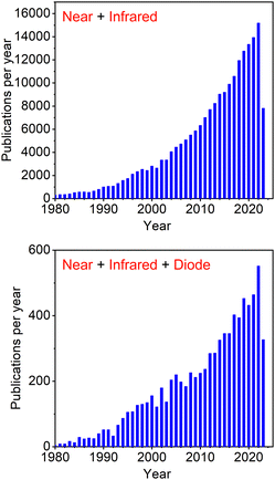 | ||
| Fig. 1 Number of papers published per year according to Scopus search for keywords “Near” + “Infrared” and “Near” + “Infrared” + “Diode”. | ||
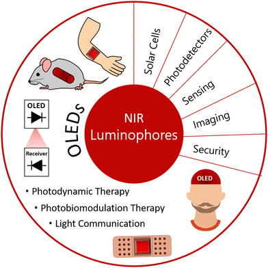
NIR photo- and electroluminescence is desired for multiple uses, including visible light communications (VLCs), night vision, and security applications.1,2 NIR light (700–1400 nm) coincides with the absorption minimum of the biological tissue, the so-called “window of transparency” and thus can be used in applications where light should penetrate deep into the tissue. Such uses include photodynamic therapy (PDT),3–6 photobiomodulation therapy (PBMT) or blood oximetry. Introducing NIR into organic light-emitting diodes (OLEDs) therefore allows these devices to be small, thin and flexible and thus minimising their invasiveness, weight or simply allowing for incorporation into small consumer electronics. We discuss applications of NIR luminescence and NIR OLEDs more in detail in the following section.
The most critical issue in the subject of NIR luminescence is the so-called energy gap law.7 The law states that two electronic states involved in a radiative transition (i.e. S1 → S0) couple stronger through the vibronic ladders of the ground state with reduction of the energy gap between them. The most important consequence of this law is the increase of the non-radiative decay rate knr between the two electronic states as the energy gap ΔE decreases, described mathematically as:7,8
Another problem often affecting NIR luminophores is that their extended π-conjugated structure promotes intermolecular interactions, leading to aggregation-caused quenching, for example.9,10 Interestingly, what for some types of NIR emitters is an issue, benefits others – here many platinum(II) complexes are a great example of how aggregation supports their NIR phosphorescence.11 Another feature of large π-conjugated luminophores is their often low solubility and large molecular weight which can complicate purification, solution-processing or sublimation. An additional complication which relates solely to metalorganic luminophores is reduction of the metal character as the π-conjugated ligand constituents expand, leading to a significant hindering of their phosphorescent properties.12
Finally, for charge-transfer donor–acceptor (D–A) emitters, such as thermally activated delayed fluorescence (TADF) systems, shifting the photoluminescence to deep red and NIR requires a clever engineering of the D and A units. Such design must involve sufficiently small HOMO–LUMO gap for emission in the NIR region imposed by introduction of strong donor and acceptor groups. Such strong charge transfer character may lead to low oscillator strength f(S1 → S0) or significant solvation-induced quenching, which hinder the luminescent behaviour.
In this work we discuss in detail how the general and particular problems arising in NIR luminophores are approached and resolved. We start from discussing the most significant in our view NIR OLED luminophores: platinum(II), iridium(III), and osmium(II) complexes to then move to similarly important various groups of metal-free TADF emitters to then discuss other groups of NIR OLED emitters, such as conventional fluorescent luminophores and emerging, new group of radical (doublet) luminophores.
The most important characteristics of OLED devices are the external quantum efficiency ηext, electroluminescence maximum λEL and its spectral distribution as well as radiant emittance (mW cm−2) or radiance (mW Sr−1 m−2). Here the authors of this work note that for visible light OLEDs the commonly accepted equivalent (or replacement) of these last two parameters is luminance (cd m−2). Luminance as a photopic property and thus does not apply to light outside of the visible region, hence luminance of NIR OLEDs only describes the visible components of their electroluminescence (i.e. ideal NIR OLEDs have zero luminance). Radiance and radiant emittance cannot be compared directly and authors of this review found that to hinder the comparison between devices characterised using these two different metrics. Hence, we believe that the use of only one of these units would benefit NIR OLED research. Given that radiant emittance and luminance are both defined through an active area of the pixel, the use of the former for NIR is well justified.
Authors of this review would like to suggest to use radiant emittance in mW cm −2 as the standard unit for describing the emitted radiant flux in NIR OLEDs.
We also point out an important and often overlooked problem related to the spectral distribution of broadband NIR emitters. Authors often focus on the long wavelength emission spectral maxima, while the onset of the spectrum lies still within the visible range (<700 nm, Fig. 2). This spectral characteristic will be perceived as a deep red “glow” of NIR OLEDs. This may be perceived as a potential signature of their low quality as the common expectation towards NIR light is their invisible character. Furthermore, in many applications the unintended visible spectral component of NIR OLEDs may be detrimental to the function, such as in security applications or VLCs. Hence, we believe that the relatively more narrowband NIR emitters offer the greatest promise for being the most desired type of a NIR luminophore.
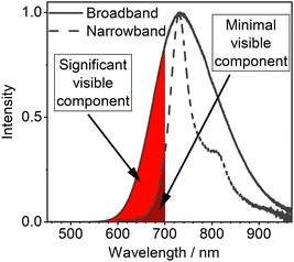 | ||
| Fig. 2 Visualised contribution of visible components in broadband and narrowband NIR OLEDs with similar electroluminescence maxima. | ||
We have structured the review in such a way that we use distinctive compound acronyms where they are widely employed. For those groups of NIR luminophores where the use of distinctive acronyms is less common (or use of such acronyms would not be helpful for the readers), we decided to use consecutive numbering of luminophores within each section. In this way the luminophores are easily traceable, which we hope benefits the readers of this review.
2. Applications of NIR OLEDs and luminophores
NIR emitting luminophores have many important applications and the number of new uses is consistently growing (Fig. 3). This includes non-invasive imaging and security applications, photodynamic therapy,13 sensing,14,15 and solar cells,16,17 for example. The luminophores used for such applications include fluorescent materials like boron-dipyrromethenes (BODIPYs),18–20 metalorganic phosphorescent materials, TADF21 and metal-free room temperature phosphorescence (RTP)22,23 amongst others as well as inorganic nanoparticles,24,25 H- and J-dimers of organic materials and aggregates.26–28 Red emitting fluorophores are often planar molecules with extended π conjugation, such as rylenes, porphyrins and electron donor–acceptor (D–A) systems. Organic fluorophores can have broad PL spectra (large full width at half maximum, FWHM values), however there are classes of dyes like BODIPYs and rylenes that can afford high colour purity (small FWHM) as well as good PLQY values. The main challenges for the NIR fluorophores in OLED applications are overcoming the energy gap law and aggregation-induced quenching.29 These two features are often exacerbated in solid state applications, like OLED devices.NIR emitting materials are not only important for development of OLEDs but they are also invaluable in biological applications as NIR wavelengths do not overlap with cells' autofluorescence (AFL). Cellular AFL spectra encompass large parts of the spectral range. For example, flavins, nicotinamide adenine dinucleotide (NAD), and lipofuscin emit green, blue, and orange light, respectively, when excited at appropriate wavelengths or a UV laser.30 For this reason, AFL frequently overlaps with the spectrum of fluorophores used for research purposes, and therefore interferes with the fluorescent microscopy, hence the importance of developing emissive NIR materials for imaging applications is crucial.30 This itself is a challenge as the energy gap law makes this task arduous.7,31 This effect is vastly exacerbated in solid state applications due to additional non-radiative processes playing part. All of the above makes the design and applications of such NIR dyes a challenge for real life applications.32 NIR emitters in combination with NIR excitation allow for better imaging of live cells. This is because NIR light can penetrate biological tissues33 with minimum interference due to reduced absorption and scattering by biological material, such as skin and blood, which is of crucial importance for potential medical applications.34 They can also prove useful in organic solar cells as they often absorb the energy across the whole of the visible part of the electromagnetic spectrum.
In the context of technological applications, NIR OLEDs are very attractive light sources for biomedical applications that use light to probe drugs, reduce pain and inflammation, improve circulation, and manipulate, or treat biological matter. The inherent mechanical flexibility of OLEDs and their compatibility with a wide range of substrates and geometries are the main advantages in this context as well as deep penetration into skin tissues as above mentioned.33 Below we discuss a few selected recent reports that successfully utilize red/NIR OLEDs in a range of different biomedical applications. In our review we discuss more broadly the application of not only NIR but also red OLEDs to exemplify a wider area of applications where NIR OLED can also be used. Many remarkable works and various applications have been described in earlier reviews and we direct the readers there.40–42 There the readers will find detailed strategies for improving device performance, encapsulation, and miniaturization towards rapid development of OLEDs in biomedicine.
The first example highlighting the use of OLEDs in photodynamic therapy (PDT) involves activation of a photosensitizer with a light source to produce reactive species that can kill neighbouring target cells. Photosensitisers used for this purpose display high intersystem crossing (ISC) rates upon optical excitation. The thus formed triplet excitons interact with molecular oxygen (3O2), producing its excited state singlet form 1O2, but also producing other reactive oxygen species.43–46 These reactive oxygen species are cytotoxic and thus attack nearby cells and bacteria. The first requirement for efficient PDT is a good match between the emission spectrum of the light source and the absorption of the photosensitizer. Activation wavelength in most of the photosensitizers used lays between 600 and 750 nm, while it should be <800 nm to provide enough energy to produce singlet oxygen. Furthermore, it is vital to use light sources that provide high output intensities (radiant emittance) with low heat generation as well as high uniformity to deliver similar light doses over the treated area.
The use of OLED PDT for treating skin cancer has been successfully demonstrated over a decade ago47 and recent works show important achievements towards device optimization with significant cancer cell death observed. One of the current challenges in the field is the usually low light output of typical OLEDs. An effective method of increasing the light output of OLEDs is to stack many devices together. For example, multiple (N) OLEDs can be connected in parallel through a common cathode and anode to realize parallel-stacked OLEDs with N-fold higher power output. Choi et al.48 have developed parallel-stacked OLEDs showing operating reliability of over 100 h even at a high power of 35 mW cm−2. In this study the photosensitizer absorbes OLED light (λEL = 660 nm) producing singlet oxygen that selectively destroys tumour cells. Remarkably, when the device was applied in vitro to treat skin melanoma, cell viability reduction of 24% was observed after only 0.5 h of irradiation (Fig. 4).
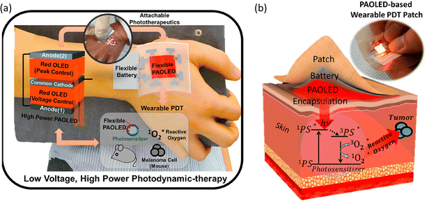 | ||
| Fig. 4 (a) Schematic illustration of the red PAOLED-based wearable PDT system. (b) Schematic illustration of PDT treatment principle and a photo of the PAOLED-based wearable PDT patch. Adapted with permission from ref. 48. Copyright 2020 American Chemical Society. | ||
Samuel et al.49 explored OLED PDT to kill bacteria. They developed flexible top-emitting OLEDs with tuneable emission (λEL = 669–737 nm), high irradiance, low driving voltage, long operational lifetimes, and adequate shelf-life for practical applications. They performed a detailed study of OLED PDT for killing Staphylococcus aureus and showed their OLEDs combined with a photosensitizer to kill more than 99% of the bacteria. This study indicates a vast potential of OLEDs in treating bacterial infections. Later, the same research group used red OLEDs for treating cutaneous leishmaniasis.50 They found that even at very low OLED radiosity Leishmania are effectively killed, demonstrating the potential for ambulatory treatment of cutaneous leishmaniasis.
Furthermore, NIR OLEDs are explored in photobiomodulation therapy (PBMT), which is a treatment that uses low-power light to reduce pain and inflammation, improve blood circulation and accelerate wound healing. The underlying mechanism behind PBMT depends on the type of cell treated or the molecular processes involved and is not yet fully understood. Choi et al.51 developed a palm-sized wearable PBM patch weighting only 0.82 g (676 μm thin) capable of accelerating wound healing. Cell proliferation and migration together with tissue formation are vital for wound healing. Their results showed that OLEDs effectively stimulated fibroblast (major type of dermal cells) proliferation as well as enhanced fibroblast migration. The wearable patch consists of several flexible OLED modules and a battery module with a patch to allow attachment to the human body, all of which are in a laminated structure. Regarding OLED performance, they showed controlled emission wavelength between 600–700 nm region with radiosity >10 mW cm−2 for each wavelength. Devices also showed reliability of more than 300 h in actual environments and good flexibility with 20 mm bend radius. Recent works from the same research group showed incredible improvements of device parameters. They demonstrated ultra-thin OLEDs (10 μm) with a thin transferable barrier (4.8 μm).52
Additionally, Lee et al.66 demonstrated first use of red OLEDs in PBMT for hair growth and showed a promising non-invasive therapeutic modality for alopecia.67 Their results demonstrated that OLED light can increase hair length by a factor of 1.5 as compared to the control, while the hair regrowth area is enlarged by over 3 times after 20 days of treatment. The authors identified two key factors that facilitate hair follicle regeneration: (1) increased utophagy during the anagen phase of the hair growth cycle; and (2) increased blood oxygen content promoted by the accelerated microvascular blood flow.
PBM is also explored for inner-body applications such as in the work reported by Yoo et al.,68 which proposed a deep red cylindrical OLED catheter as an effective PBM platform for tubular organs. Their biocompatible and airtight OLED device can operate in aqueous environments for extended periods of time. It was used in a pilot study targeting treatment of type 2 diabetes mellitus in rats. The catheter delivering 798 mJ of energy showed to reduce hyperglycemia and insulin resistance when compared to the sham group. These remarkable findings could have implications that extend well beyond diabetes, potentially opening the door to future clinical investigations into the use of inner-body PBM for treatment of various other medical conditions.
Apart from biomedical applications, the use of OLEDs in visible light communications (VLCs)69 is a fast-growing trend. OLEDs are not the obvious candidates for use in communications due to the low mobility of organic semiconductors (∼10−6–10−2 cm2 V−1 s−1) resulting in low modulation bandwidths – compared to ‘inorganic’ VLC systems that achieve Gb s−1 (Gbps). However, OLEDs are still suitable for a wide range of prospective connections as those expected for the implementation of the internet-of-things (IoT), which only require data rates in the range of a few Mb s−1 (Mbps). OLEDs are appealing in this context due to their low cost large area fabrication, recyclability and/or sustainability, and mechanical flexibility. Extending the spectral range of these devices into NIR not only expands the bandwidth of VLC links but also paves the way for their integration into many applications exploiting NIR radiation such as security, biosensors, and biomedical applications. In this context Cacialli et al.70 demonstrated a “real-time” VLC setup achieving data rates of 2.2 Mbps, the highest rates ever reported for an online unequalised VLC link based on solution-processed OLEDs. Their OLEDs showed red-to-NIR EL (λEL = 650–800 nm) with ηext up to 2.7%. Thus, they demonstrated the possibility of achieving Mbps data rates without computationally complex and power-demanding equalisers, satisfying the requirements for IoT and biosensing applications.
3. Platinum(II) complexes
We begin our review with the most important group of NIR OLED luminophores. Platinum(II) complexes remain the most efficient NIR OLED emitters to date and hold the record for the longest wavelength NIR OLEDs with practical efficiencies. Luminescent platinum(II) complexes consist of a metal centre, a Pt2+ ion, and organic/inorganic ligands of various types. Platinum(II) complexes attain a square planar geometry around the central atom, which has a significant effect on their luminescent properties. Typically flat structures of these transition metal complexes lead to a significant degree of intermolecular interactions, resulting in aggregation in the ground state and excimer formation in the excited state. We will use the terms monomer or unimolecular to refer to the emissive behaviour originating from isolated molecules, while excimer or aggregate will refer to bi- and for the latter also multimolecular species.The emissive properties of platinum(II) complexes rely on the mixing of metal d orbitals with π orbitals of the organic ligands. Generally speaking, monomeric platinum complexes emit from the triplet metal-to-ligand charge-transfer (3MLCT), ligand-centred (3LC) states, or their mixtures. Rigidity of their structure as well as admixtures of the 3LC states often lead to a relatively narrowband luminescence with a clearly resolved vibronic structure, a feature of importance for colour purity in visible light OLEDs71 as well as “NIR purity” in near infrared electroluminescent devices.
Aggregate platinum(II) complexes present somewhat opposite characteristics: they display broadband and featureless emission spectra, characteristic of the strong triplet metal–metal-to-ligand charge-transfer (3MMLCT) emissive states. Hence, the dominating NIR emission is often accompanied by a measurable amount of undesired red luminescence. Despite that flaw however, aggregate platinum(II) complexes are among the most efficient NIR emitters known to date.
Monomeric complexes
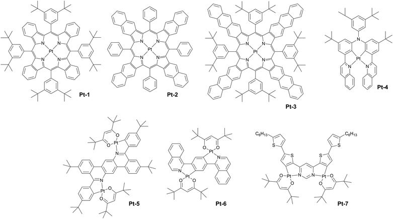
The first platinum(II) compounds to give efficient NIR electroluminescence were porphyrin complexes (see Fig. 5 for molecular structures and Table 1 for summary of OLED characteristics). Thanks to the exceptional rigidity of porphyrin cores and small energy gaps they are strongly emissive in deep red or near infrared. Most prominent examples are Pt-1, Pt-2, and Pt-3 reported by Reynolds, Xue, Schanze et al.35 They display long wavelength EL extending out as far as to ∼1000 nm. The authors reported narrowband NIR OLEDs achieving λEL = 773 nm, ηext = 9.2% (Pt-1), λEL = 896 nm, ηext = 3.8% (Pt-2), and λEL = 1005 nm, ηext = 0.2% (Pt-3) (Fig. 6). The first two were fabricated using vacuum deposition, while the complex Pt-3 could not be sublimed, likely due to its high molecular weight, and thus the reported OLED was solution-processed. We note there have been relatively few other examples of monomeric Pt(II) complexes that would come close to these characteristics.| Complex | λ EL , nm | η ext , % | OLED architecturec | Source |
|---|---|---|---|---|
| a EL maxima. b Maximum external quantum efficiency. c We direct readers to the source articles for explanation of non-common acronyms used in describing OLED architectures. | ||||
| Pt-1 | 773 | 9.1 | ITO/NPB/4% Pt-1:AlQ3/Bphen/LiF/Al | 35 |
| Pt-2 | 896 | 3.8 | ITO/NPB/8% Pt-2:CBP/Bphen/LiF/Al | 35 |
| Pt-3 | 1005 | 0.20 | ITO/PEDOT:PSS/2% Pt-3:PVK:PBD (60![[thin space (1/6-em)]](https://www.rsc.org/images/entities/char_2009.gif) : :![[thin space (1/6-em)]](https://www.rsc.org/images/entities/char_2009.gif) 40)/LiF/Ca/Al 40)/LiF/Ca/Al |
35 |
| Pt-4 | 730 | 5.2 | ITO/HAT-CN/TPD15/TCTA/3% Pt-4:DMIC-CZ:DMIC-TRZ/ANT-BIZ/Liq/Al | 36 |
| Pt-5 | 724 | 0.97 | ITO/PEDOT:PSS/poly-TPD/2% Pt-5:PVK:OXD-7 (70![[thin space (1/6-em)]](https://www.rsc.org/images/entities/char_2009.gif) : :![[thin space (1/6-em)]](https://www.rsc.org/images/entities/char_2009.gif) 30)/TmPyPB/Ba/Al 30)/TmPyPB/Ba/Al |
37 |
| Pt-6 | 746 | 0.58 | ITO/PEDOT:PSS/poly-TPD/3% Pt-6:PVK:OXD-7 (70![[thin space (1/6-em)]](https://www.rsc.org/images/entities/char_2009.gif) : :![[thin space (1/6-em)]](https://www.rsc.org/images/entities/char_2009.gif) 30)/TmPyPB/CsF/Al 30)/TmPyPB/CsF/Al |
38 |
| Pt-7 | 731 | 3.6 | ITO/HIL 1.3N/PVKH/5% Pt-7:TPD:PBD (60![[thin space (1/6-em)]](https://www.rsc.org/images/entities/char_2009.gif) : :![[thin space (1/6-em)]](https://www.rsc.org/images/entities/char_2009.gif) 40)/TPBi/LiF/Al 40)/TPBi/LiF/Al |
39 |
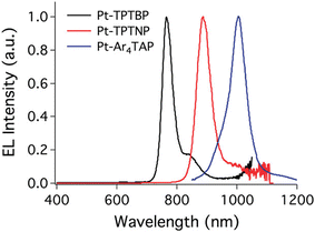 | ||
| Fig. 6 Electroluminescence spectra of porphyrin platinum(II) complexes. From left: Pt-1, Pt-2, and Pt-3. Adapted with permission from ref. 35 Copyright 2011 American Chemical Society. | ||
Monomeric platinum(II) complexes have not been extensively studied for use in NIR OLEDs and there are only a few more recent examples of complexes worthy of note. It appears that the typical design of this group of complexes poses limitations in their use as monomeric NIR emitters. For example, the usually planar structure of Pt(II) complexes leads to aggregation, which may promote luminescence quenching or cause the complexes more favourably emitting NIR from the aggregate state. On the other hand, to attain small energy gap in Pt(II) complexes necessary for NIR luminescence one may increase the conjugation of the chelating ligands, decreasing the metal character of the excited states. Hence, many deep red/NIR complexes display long phosphorescence lifetimes.12
A recent example of a N,C,C,N-type complex Pt-4 has been studied by Zhang, Yang and co-workers.36 The complex displays λEL = 730 nm and a relatively modest ηext = 5.2%.
The use of complexes employing two or more platinum atoms showed to partially resolve the problem by inducing higher density of states, hence escalating coupling between the T1 emissive state and singlet excited states Sn.72 Examples of such complexes are: Pt-537 (λEL = 724 nm, ηext = 0.97%), Pt-638 (λEL = 746 nm, ηext = 0.58%), and Pt-739 (λEL = 731 nm, ηext = 3.6%), see Fig. 7. These three diplatinum(II) complexes have been used in solution-processed OLEDs rather than vacuum-deposited devices. The likely reason is that the molecular weight of these complexes is too large for effective thermal evaporation or sublimation below decomposition temperature. This feature highlights the limitations of many diplatinum(II) or bimetallic complexes more generally.
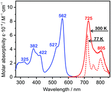 | ||
| Fig. 7 Absorption and photoluminescence spectra of Pt-7 in toluene solution at 300 K and 77 K. Reproduced from ref. 39 with permission from the Royal Society of Chemistry. | ||
It appears so far that monomeric platinum(II) complexes are not the most popular examples of NIR OLED emitters which may be due to their apparent weaknesses. However, they pose an interesting example of rigid luminophores with often relatively narrowband photoluminescence, hence they present a potential to supersede aggregate complexes – currently the best in terms of efficiency, but displaying broadband spectra by their nature. A promising pathway to overcome the limitations of phosphorescent platinum(II) complexes is the use of TADF complexes first introduced by Pander, Kozhevnikov, Williams et al.73 TADF allows accelerating the radiative decay of platinum(II) complexes regardless of the weakening excited state metal character in NIR, hence counteracting the detrimental trends affecting phosphorescent counterparts.
In conclusion, the authors of this review believe that there is a potential for platinum(II) complexes to become more important NIR OLED emitters in the future due to their ability to emit narrowband luminescence.
Aggregate complexes
Aggregate platinum(II) complexes are currently the most important NIR-emissive luminophores as they display ground breaking efficiencies with little to no competition from other types of luminophores, including monomeric complexes of the same metal (Fig. 8 for molecular structures and Table 2 for OLED characteristics). The luminescent properties of aggregate complexes are highly reliant on concentration, hence their typical form used in OLEDs are neat films. This creates challenges, but also opportunities in OLED design. Such neat emissive layers lead to large consumption of the platinum(II)-containing emitter, while the complex itself has to take part in charge transfer as no host is present. On the other side, such neat layers of planar molecules often display a degree of anisotropy, which may be beneficial for improving out-coupling efficiency of NIR OLEDs.74 A noteworthy subgroup are complexes where the MMLCT states, identical to those in aggregated complexes, are introduced within one molecule. For the purpose of this review these will be called intramolecular aggregates. These complexes retain their MMLCT emission in dilution and thus can be used at low concentrations, dispersed in a host matrix. This eliminates the problems posed by intermolecular aggregates. | ||
| Fig. 8 (left) Electroluminescence spectra of Pt-21 in neat emissive layer; (right) HOMO and LUMO in the T1 geometry of Pt-24 pentamer. Reproduced from ref. 61 with permission from the Royal Society of Chemistry. | ||
| Complex | λ EL , nm | η ext , % | OLED architecturec | Source |
|---|---|---|---|---|
| a EL maxima. b Maximum external quantum efficiency. c We direct readers to the source articles for explanation of non-common acronyms used in describing OLED architectures. | ||||
| Pt-8 | 715 | 10.0 | ITO/TPD:PC/CBP/Pt-8/OXD-7/Ca | 53 |
| Pt-9 | 775 | 0.30 | ITO/TPD:PC/TCTA/Pt-9/TAZ/LiF/Al | 54 |
| Pt-10 | 855 | ∼1 | ITO/TPD:PC/TCTA/Pt-10/TAZ/LiF/Al | 55 |
| Pt-11 | 707 | 11.19 | ITO/MoO3/TAPC/TCTA/Pt-11/B3PYMPM/LiF/Al | 56 |
| Pt-12 | 700 | 24.0 | ITO/HAT-CN/NPB/mCP/Pt-12/TPBi/Liq/Al | 57 |
| Pt-13 | 754 | 7.51 | ITO/TAPC/TCTA/mCP/Pt-13/3TPYMB/TPBi/LiF/Al | 58 |
| Pt-14 | 794 | 10.61 | ITO/TAPC/TCTA/mCP/Pt-14/3TPYMB/TPBi/LiF/Al | 58 |
| Pt-15 | 758 | 9.65 | ITO/TAPC/TCTA/mCP/Pt-15/3TPYMB/TPBi/LiF/Al | 58 |
| Pt-16 | 803 | 9.58 | ITO/TAPC/TCTA/mCP/Pt-16/3TPYMB/TPBi/LiF/Al | 58 |
| Pt-17 | 900 | 1.70 | ITO/MoO3/10% MoO3:NPB/NPB/TCTA/mCP/Pt-17/PO-T2T/TPBi/Liq/Al | 59 |
| Pt-18 | 890 | 2.10 | ITO/MoO3/10% MoO3:NPB/NPB/TCTA/mCP/Pt-18/PO-T2T/TPBi/Liq/Al | 59 |
| Pt-19 | 930 | 2.0 | ITO/MoO3/10% MoO3:NPB/NPB/TCTA/mCP/Pt-19/PO-T2T/TPBi/Liq/Al | 59 |
| Pt-20 | 790 | 0.9 | ITO/HAT-CN/TSBPA/Pt-20/PO-T2T/LiF/Al | 60 |
| Pt-21 | 944 | 0.3 | ITO/HAT-CN/TSBPA/Pt-21/PO-T2T/LiF/Al | 61 |
| Pt-22 | 736 | 2.5 | ITO/HAT-CN/TSBPA/Pt-22/PO-T2T/LiF/Al | 61 |
| Pt-23 | 820 | 1.2 | ITO/HAT-CN/TSBPA/Pt-23/PO-T2T/LiF/Al | 60 |
| Pt-24 | 857 | 1.1 | ITO/HAT-CN/TSBPA/Pt-24/PO-T2T/LiF/Al | 61 |
| Pt-25 | 734 | 4.2 | ITO/HAT-CN/TSBPA/Pt-25/PO-T2T/LiF/Al | 61 |
| Pt-26 | 995 | 1.96 | ITO/MoO3/NPB/Pt-26/CN-T2T/CN-T2T:Liq/Al | 62 |
| Pt-26-d | 995 | 3.83 | ITO/MoO3/NPB/Pt-26-d/CN-T2T/CN-T2T:Liq/Al | 62 |
| Pt-27 | 930 | 3.59 | ITO/MoO3/NPB/Pt-27/CN-T2T/CN-T2T:Liq/Al | 62 |
| Pt-27-d | 930 | 5.17 | ITO/MoO3/NPB/Pt-27-d/CN-T2T/CN-T2T:Liq/Al | 62 |
| Pt-28 | 1002 | 2.08 | ITO/MoO3/NPB/Pt-28/CN-T2T/CN-T2T:Liq/Al | 62 |
| Pt-29 | 704 | 8.86 | ITO/PEDOT:PSS/6% Pt-29:PVK:OXD-7:FIrPic/TmPyPB/Ba/Al | 63 |
| Pt-30 | 692 | 17.2 | ITO/HAT-CN/TAPC/TCTA/3% Pt-30:DMIC-CZ:DMIC-TRZ/ANT-BIZ/Liq/Al | 64 |
| Pt-31 | 760 | 2.73 | ITO/PEDOT:PSS/2% Pt-31:CBP/TmPyPB/CsF/Al | 65 |
To the best of the authors’ knowledge there has been no conclusive experimental study determining the spin nature of the emissive MMLCT states in platinum aggregates, but due to the strong spin–orbit coupling induced by the metal centre they are broadly recognised as triplet emitters. The 3MMLCT states are created by interacting Pt centres of the aggregated molecules.75 The molecules stack in a fashion where the metal centres remain roughly on the Z-axis of the aggregate and for dimers and excimers this interaction is often akin, leading to similar PL spectra of these two related species. Formation of aggregates larger than dimers, i.e. trimers, tetramers, pentamers, etc. is responsible for the extremely long wavelength photo- and electroluminescence of this group of NIR emitters.61
Historically, the most important are most likely complexes of tridentate dipyridylbenzene ligand of the form Pt(NCN)-X, where usually X = halogen or pseudohalogen. These types of complexes have been broadly investigated in the past two decades by Williams, Cocchi and Kalinowski. The most profound examples of this group of complexes are Pt-8,53 the archetypal example (λEL = 715 nm, ηext ∼ 10%), Pt-954 decorated with –CF3 groups para to nitrogen which is found to red shift their photo- and electroluminescence (λEL = 775 nm, ηext = 0.3%), and Pt-1055 where the X = Cl auxiliary ligand was replaced with thiocyanate X = NCS, leading to a further red shift in respect to Pt-8 (λEL = 855 nm, ηext ∼ 1%). The actual role of the X = NCS ancillary ligand was, at the time, not fully understood. Since then other designs affording NIR electroluminescence have been suggested, such as complexes of tetradentate N,C,N,O ligands proposed by Che and co-workers.56 For example, complex Pt-11 featuring an azafluorene fragment displays λEL = 707 nm and ηext = 11.19%.
Probably the most successful so far group of NIR-emissive platinum(II) complexes was proposed by Chou and Chi in 2017. The homo- and heteroleptic complexes of bidentate pyridyl pyrazolate and pyrazinyl pyrazolate ligands decorated with –CF3 groups achieved high ηext exceeding 20% at λEL ∼ 700 nm. For example, complex Pt-12 gave λEL = 740 nm and ηext = 24%, setting out an efficiency record for NIR OLEDs at the time.57 The authors clearly hint that long wavelength photo- and electroluminescence of their complexes originates from aggregates larger than dimers (i.e. trimers).
A further modification of these complexes by Lee, Chou, and Chi gave rise to highly efficient heteroleptic complexes of bidentate ligands, featuring the known pyridyl pyrazolate or pyrazinyl pyrazolate ligands and a novel pyridyl pyrimidinate ligand.58 The new complexes display exceptionally high NIR OLED performance, ηext ∼ 10% and λEL ∼ 800 nm. The molecules Pt-13 (λEL = 754 nm, ηext = 7.51%), Pt-14 (λEL = 794 nm, ηext = 10.61%), Pt-15 (λEL = 758 nm, ηext = 9.65%), Pt-16 (λEL = 803 nm, ηext = 9.58%) feature a similar structural motif with small variations in the peripheral groups or the number of nitrogen heteroatoms. The authors also point out the importance of the ligand design not only for reducing the energy of the 3MMLCT states, but also for enhancing the intermolecular π–π and Pt⋯Pt interactions leading to a larger delocalisation of the excited state and more red shifted luminescence.
Liao, Chi and Chou demonstrated the importance of the size of the Pt–Pt aggregates for overcoming the energy gap law. They show that delocalization of the exciton over several aggregated molecules decouples the excited state from the vibronic ladders of the ground state S0, leading to reduced non-radiative decay and increased photoluminescence quantum yield in NIR. The complexes reported in their work feature unprecedentedly long wavelength luminescence and high OLED efficiency: Pt-17 (λEL = 900 nm, ηext = 1.7%), Pt-18 (λEL = 890 nm, ηext = 2.1%), and Pt-19 (λEL = 930 nm, ηext = 2.0%).59
Recent works by Pander, Williams, and Dias discuss the role and mechanism of aggregation in platinum(II) complexes in detail, showing a clear correlation between aggregate size and the PL wavelength. Furthermore, they prove that the NIR-emissive neat films comprise aggregates of various sizes. They also demonstrate that efficient NIR 3MMLCT luminescence can be obtained from OLED emissive layers as thin as ∼1 nm, leading to significantly reducing consumption of the emitter. Reported complexes Pt-23 and Pt-20 display λEL = 820 nm, ηext = 1.2% and λEL = 790 nm, ηext = 0.9% in OLED.60
In a follow-up work Pander, Williams, and Dias report complexes analogous to Pt-20 and Pt-23, but with the ancillary ligand X = Cl replaced with X = NCS/SCN. Although the X = NCS/SCN ligand appears to mildly blue shift the excimer PL in respect to X = Cl, it leads to a substantial degree of aggregation in neat film, spanning to ∼5–6 units (Fig. 9). This results in a significant photo- and electroluminescence red shift in the new complexes Pt-21 (λEL = 944 nm, ηext = 0.3%) and Pt-24 (λEL = 857 nm, ηext = 1.1%).61 The authors have also studied complexes, where X = I. Such change leads to only a slightly lower 3MLCT energy in respect to the X = Cl, but the neat film PL is nearly identical to the excimer PL in solution, indicative of dimers dominating in the film. The authors report a significantly higher OLED efficiency than for the X = Cl derivatives, which is ascribed to suppressing some vibrational modes that couple the T1 to the ground state. The X = I complexes give λEL = 736 nm and ηext = 2.5% for Pt-22 and λEL = 734 nm and ηext = 4.2% for Pt-25 in neat film OLEDs.
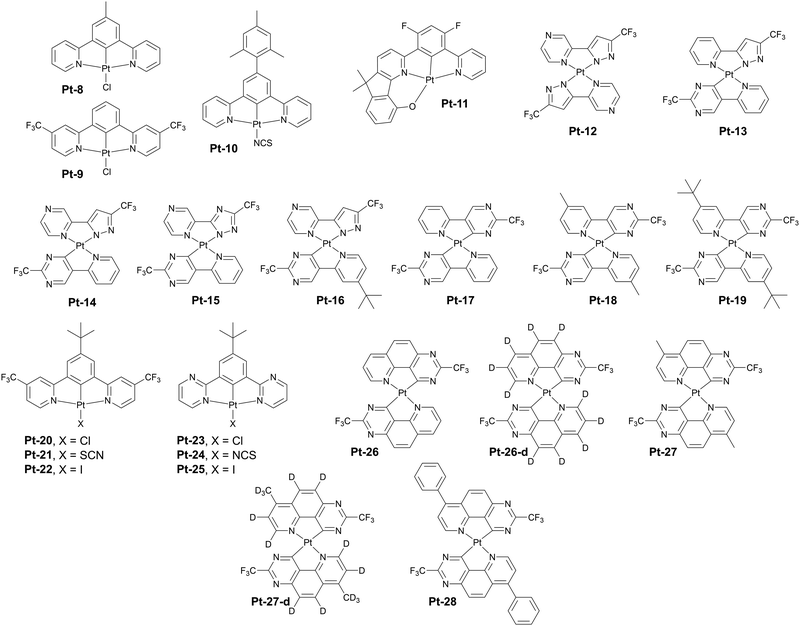 | ||
| Fig. 9 Examples of aggregating platinum(II) complexes with long wavelength NIR photo- and electroluminescence in neat films. | ||
Liao, Hung, Chi, Chou and co-workers have recently reported what we believe is the most remarkable example of an efficient NIR OLED emitter, with λEL approaching 1000 nm and ηext exceeding 4%.62 They used deuteration to alter the vibrational modes of the emitting aggregates, reducing the excited-to-ground-state coupling. For example, they present a complex Pt-26, which displays λEL = 995 nm in neat film with ηext = 1.96%, while its deuterated Pt-26-d analogue shows λEL = 995 nm and ηext = 3.83%. Methylation in the para position to the N-coordinating nitrogen gives a slightly shorter wavelength emission, but higher OLED efficiency in Pt-27λEL = 930 nm and ηext = 3.59%. The 100%-d analogue Pt-27-d displays even higher ηext = 5.17% with identical λEL = 930 nm. Finally, modification of Pt-28 with a phenyl instead of a methyl group para to nitrogen gives λEL = 1002 nm and ηext = 2.08%. To the best of our knowledge, this work presents the highest NIR OLED efficiency for an emitter with λEL close to 1000 nm.
An important subgroup of aggregate platinum(II) complexes are those displaying intramolecular as opposed to intermolecular aggregation discussed previously (Fig. 10 and 11). In this case the short Pt⋯Pt contacts are formed between two platinum(II) centres inside one molecule rather than between separate molecules. The advantage of this system is independence of their 3MMLCT emission of concentration, meaning that they can be utilised in a diluted form, in a host, rather than used as a neat emissive layer in a device. This allows for more conventional OLED structures where the charge transport is mostly carried out by the host, rather than the emitter as in the non-doped OLEDs featuring neat emissive layers. On the other hand, having two metal centres significantly increases the molecular weight of the complex, leading to vacuum thermal deposition not being possible in some cases.
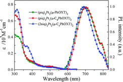 | ||
| Fig. 10 Absorption and photoluminescence of Pt-29 (blue lines) in dichloromethane. Reproduced from ref. 63 with permission from the Royal Society of Chemistry. | ||
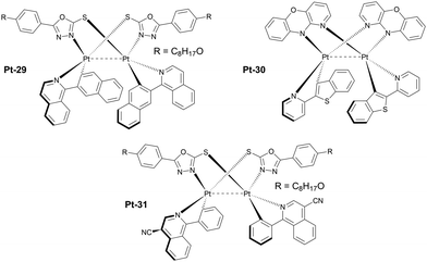 | ||
| Fig. 11 Examples of luminescent diplatinum(II) complexes which effectively form intramolecular 3MMLCT states. | ||
One of the earlier examples of such luminophores is complex Pt-29 featuring a 1,3,4-oxadiazole-2-thiolate bridging ligand and phenyl quinoline chelating ligands. It was used as an emitter in solution-processed OLEDs giving λEL = 704 nm and ηext = 8.86%.63 More recent examples of these complexes are those reported by Li, featuring a very short, ∼2.8 Å Pt⋯Pt distance due to the use of 10H-pyrido[3,2-b][1,4]benzoxazine as the bridging ligand. An example complex Pt-30 featuring a benzothiopheno pyridyl chelating ligand displays λEL = 692 nm and ηext = 17.2% in an OLED.64 Most crucially, these reported complexes are highly thermally stable and can be thermally deposited despite containing two platinum centres. This remarkable achievement makes them more desired for use in commercial applications.
In 2023 Yu, Tan, Zhu and co-workers developed an improved version of Pt-29, complex Pt-31 with a modified C,N ligand featuring a –CN substituted isoquinoline. The new complex displays λEL = 760 nm and ηext = 2.73% in a doped OLED.65
In summary, aggregate platinum(II) complexes display long wavelength photo- and electroluminescence thanks to the formation of short Pt⋯Pt contacts that give rise to 3MMLCT ground and excited states. Strategies leading to the intense and long wavelength photo- and electroluminescence in this group of emitters rely on two factors: (1) reducing the energy of the 3MMLCT states in general and (2) design promoting aggregates with long delocalisation length. They display superior OLED efficiency in NIR thanks to rigidity of the monomeric units and large delocalisation of the excited state. They are currently the best NIR OLED emitters known.
4. Other metal complexes
Despite the clear dominance of platinum(II) complexes in the area of NIR luminescence, complexes of other metals, mainly iridium(III) and osmium(II) are also of importance. Due to their significance they are discussed in detail in their individual subsections presented below. Their main advantage is the ability to display efficient NIR photo- and electroluminescence from isolated luminophores and without bimetallic structures. Thanks to the d6 configuration of the central ions they form hexacoordinated ball-like complexes rather than the planar structures formed by platinum(II) ions. Therefore, they are more likely to be sublimable, more soluble, and less susceptible to aggregation. Also, complexes of these two metals allow for a larger variety of potential structures due to the 3-dimensional distribution of coordinating ligands.Iridium(III) complexes
Complexes of iridium(III) are probably the most diverse among all the metal complexed discussed in this review (see Fig. 12 for molecular structures and Table 3 for OLED characteristics). A probable reason for that is the long standing history of research on iridium(III) complexes over the last twenty years and their application in OLEDs.83 Complexes of this metal remain the industrial standard for green and red pixel in commercial OLED displays. Iridium(III) adopts an octahedral geometry in complexes, leading to a large variety of ligand motifs and their combinations. Complexes of this heavy metal emit predominantly through their 3MLCT or 3MLCT + 3LC states, however recent computational and experimental studies suggest that some also display fluorescent behaviour in the form of TADF.84 Although examples of deep red and NIR-emissive iridium(III) complexes are plentiful, not many display performance comparable to that displayed by platinum(II) complexes. Thus, in this section we focus on the most prominent, recent developments in the subject.| Complex | λ EL , nm | η ext , % | OLED architecturec | Source |
|---|---|---|---|---|
| a EL maxima. b Maximum external quantum efficiency. c We direct readers to the source articles for explanation of non-common acronyms used in describing OLED architectures. | ||||
| Ir-1 | 765 | 4.50 | ITO/NPB/6% Ir-1:DIC-TRZ/TPBi/Mg:Ag | 76 |
| Ir-2 | 824 | 0.50 | ITO/NPB/6% Ir-2:DIC-TRZ/TPBi/Mg:Ag | 76 |
| Ir-3 | 847 | 0.20 | ITO/PEDOT:PSS/5% Ir-3:CzTPA-m-Trz/Bphen/LiF/Al | 77 |
| Ir-4 | 718 | 6.80 | ITO/PEDOT:PSS/poly-TPD/0.8% Ir-4:PVK:OXD-7 (70![[thin space (1/6-em)]](https://www.rsc.org/images/entities/char_2009.gif) : :![[thin space (1/6-em)]](https://www.rsc.org/images/entities/char_2009.gif) 30)/TmPyPB/CsF/Al 30)/TmPyPB/CsF/Al |
78 |
| Ir-5 | 760 | 1.50 | ITO/PEDOT:PSS/poly-TPD/0.8% Ir-5:PVK:OXD-7 (70![[thin space (1/6-em)]](https://www.rsc.org/images/entities/char_2009.gif) : :![[thin space (1/6-em)]](https://www.rsc.org/images/entities/char_2009.gif) 30)/TmPyPB/CsF/Al 30)/TmPyPB/CsF/Al |
78 |
| Ir-6 | 704 | 6.90 | ITO/PEDOT:PSS/poly-TPD/0.8% Ir-6:PVK:OXD-7/TmPyPB/CsF/Al | 79 |
| Ir-7 | 728 | 5.40 | ITO/PEDOT:PSS/poly-TPD/0.8% Ir-7:PVK:OXD-7/TmPyPB/CsF/Al | 79 |
| Ir-8 | 708 | 13.70 | ITO/PEDOT:PSS/TAPC/2% Ir-8:CBP/TmPyPB/CsF/Al | 79 |
| Ir-9 | 718 | 12.30 | ITO/PEDOT:PSS/TAPC/2% Ir-9:CBP/TmPyPB/CsF/Al | 79 |
| Ir-10 | 690 | 10.60 | ITO/HAT-CN/TAPC/mCP/15% Ir-10:CBP/TPBi/LiF/Al | 80 |
| Ir-11 | 706 | 9.60 | ITO/HAT-CN/TAPC/mCP/15% Ir-11:CBP/TPBi/LiF/Al | 80 |
| Ir-12 | 784 | 5.42 | ITO/PEDOT:PSS/10% Ir-12:CBP/DPEPO/TmPyPB/LiF/Al | 81 |
| Ir-13 | 710 | 1.10 | ITO/PEDOT:PSS/Ir-13:PVK:OXD-7/LiF/Al | 82 |
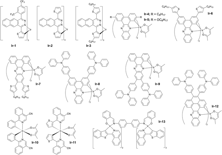
The rule of thumb for long wavelength luminescent iridium(III) complexes is the use of large π-conjugated structures as some of the ligands coordinating the central ion. An older example of such complexes are Ir-1 (λEL = 765 nm and ηext = 4.5%) and Ir-2 (λEL = 824 nm and ηext = 0.5%) introduced by Qiao and others in 2017 and using benzo[g]phthalazine-based chelating ligands.76 Qiao et al. have subsequently demonstrated that photoluminescence red shift can be observed simply by using a 2-alkylated thiophene instead of undecorated thiophene, hence obtaining complex Ir-3 with a visibly red shifted emission in respect to Ir-2, λEL = 847 nm and ηext = 0.2%.77 The difference in behaviour between Ir-2 and Ir-3 highlights the significance of σ-donating properties of simple alkyl groups.
Other noteworthy examples of similar design include the use of dibenzo[a,c]phenazine as the π-conjugated chelating ligand by Zhu and others78 in Ir-4 (λEL = 718 nm and ηext = 6.8%) and Ir-5 (λEL = 760 nm and ηext = 1.5%) in solution-processed OLEDs (Fig. 13). The idea of using dibenzo[a,c]phenazine as the chelating ligand has been explored further by Wang, Zhu et al. as they decorated the phenazine core with electron donor hexyl-thienyl or 4-(N,N-diphenylamino)phenyl groups. The resultant iridium(III) complexes gave remarkable NIR OLED performance: Ir-6 (λEL = 704 nm and ηext = 6.9%), Ir-7 (λEL = 728 nm and ηext = 5.4%), Ir-8 (λEL = 708 nm and ηext = 13.7%), and Ir-9 (λEL = 718 nm and ηext = 12.3%).79
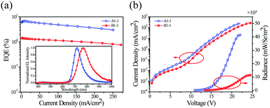 | ||
| Fig. 13 Electrical and electroluminescent characteristics of OLEDs fabricated using Ir-4 (blue lines) and Ir-5 (red lines): (a) External quantum efficiency (EQE) vs. current density – inset shows EL spectra; (b) Current density (left) and radiance (right) vs. voltage bias. Reproduced from ref. 78 with permission from the Royal Society of Chemistry. | ||
An interesting alternative design was presented by Chen, Chen, Wong et al. in which they modified structure of the commercially available Ir(piq)2(acac) by addition of a –CN group into the isoquinoline fragment (Ir-10) and by additionally replacing the C-coordinating phenyl group with thienyl (Ir-11).80 Thus, these modifications leading to increasing the electron-deficient nature of the N-coordinating site and escalating the electron-rich nature of the C-coordinating fragment resulted in a significant red shift of the electroluminescence from λEL = 626 nm in Ir(piq)2(acac) to λEL = 690 nm and ηext = 10.6% in Ir-10 and λEL = 706 nm and ηext = 9.6% in Ir-11 (Fig. 14). This design is somewhat superior to that relying solely on extended ligand conjugation as it reduces the total molecular weight of the complex, facilitating vacuum thermal evaporation.
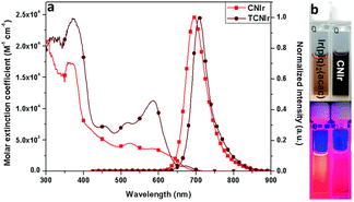 | ||
| Fig. 14 (a) Absorption and photoluminescence spectra of complexes Ir-10 (light red lines) and Ir-11 (dark red lines) in tetrahydrofuran. (b) Solutions of Ir-10 (right) and reference complex Ir(pic)2(acac) (left) photographed in visible (top) and ultraviolet light (bottom). Reproduced from ref. 80 with permission from the Royal Society of Chemistry. | ||
Most recently, Yu, Zhu, et al. reported a novel efficient NIR complex based on the structure of complexes Ir-4 to Ir-9, but with an increased conjugation of the π-conjugated fragment.81 The new metalorganic compound Ir-12 gives a long wavelength EL λEL = 784 nm and reasonably good efficiency in relation with other iridium(III) complexes in this region of electroluminescence spectrum, ηext = 5.42%.
Somewhat intriguing is the design of dinuclear iridium(III) complexes for NIR OLEDs. Although this subtopic is clearly outside of the mainstream research a one noteworthy example is shown here as a curiosity. The di-iridium(III) complex Ir-13 displays λEL = 710 nm and ηext = 1.1% in a solution-processed OLED device.82
In summary, mononuclear design clearly dominates in the subject of NIR-luminescent iridium(III) complexes, as opposed to the somewhat related platinum(II) counterparts, where dinuclear design is favoured for NIR. A likely reason for this state of the art is the different from Pt2+ electronic structure of the Ir3+ ion leading to a three dimensional octahedral structure of resultant complexes. Hence, the density of the lowest excited states is higher, leading to a better mixing between the singlet and triplet states. In this respect efficient NIR luminescence in iridium(III) complexes can effectively be achieved with the use of monometallic structures and hence bimetallic structures remain much less interesting.
The main design strategy for achieving NIR luminescence in this group of complexes is the use of large π-conjugated ligands. An alternative approach relies on increasing the electron-deficient character of the N-coordinating heterocyclic ligand. This strategy is somewhat similar to that adopted for NIR-emissive osmium(II) complexes discussed in the next subsection.
Iridium(III) complexes have shown to be efficient visible and NIR luminescent dopants in OLEDs with relatively high device efficiencies. Due to their high OLED efficiency and relatively narrowband EL they clearly offer an alternative to aggregate platinum(II) complexes. The vast majority of NIR OLEDs based on iridium(III) luminophores display electroluminescence in the short wavelength arm of the NIR region, i.e. 700–800 nm, indicating a clear need for more development in the area and towards emission in the 800–1000 nm region.
Osmium(II) complexes
Luminescent complexes of osmium(II) are relatively less common than those of platinum(II) and iridium(III), however they also play an important role as NIR OLED emitters (Fig. 15 and Table 4). Os(II) complexes display a relatively easy tuning of their luminescence colour with abundance of examples spanning from yellow-green through red and to NIR.89 Typically, complexes of this transition metal display featureless and often broadband spectra resultant from the strong MLCT character of the emissive triplet state. They are currently believed to emit from their 3MLCT states due to the strong spin–orbit coupling induced by the metal centre. It is evident however that current state-of-the-art photophysics of this group of NIR complexes lacks of detail and deserves further and more in-depth studies. Interestingly, most if not all of the NIR-luminescent Os(II) complexes feature, among others, phosphine ligands of various types. The entirety of the Os(II) complexes presented in this section have been reported by Professor Yun Chi and collaborators.| Complex | λ EL , nm | η ext , % | OLED architecturec | Source |
|---|---|---|---|---|
| a EL maxima. b Maximum external quantum efficiency. c We direct readers to the source articles for explanation of non-common acronyms used in describing OLED architectures. | ||||
| Os-1 | 718 | 2.70 | ITO/α-NPD/6% Os-1:Alq3/TAZ/LiF/Al | 85 |
| Os-2 | 814 | 1.50 | ITO/α-NPD/6% Os-2:Alq3/TAZ/LiF/Al | 85 |
| Os-3 | 739 | 5.20 | ITO/TAPC/mCP/2% Os-3:CBP/TmPyPB/LiF/Al | 86 |
| Os-4 | 710 | 11.50 | ITO/TAPC/mCP/2% Os-4:CBP/TmPyPB/LiF/Al | 86 |
| Os-5 | 776 | 3.10 | ITO/4% ReO3:TAPC/TCTA/3% Os-5:CBP/PO-T2T/LiF/Al | 87 |
| Os-5-d | 776 | 3.77 | ITO/4% ReO3:TAPC/TCTA/3% Os-5-d:CBP/PO-T2T/LiF/Al | 87 |
| Os-5-d | 776 | 3.96 | ITO/4% ReO3:TAPC/TCTA/3% Os-5-d:CBP-d/PO-T2T/LiF/Al | 87 |
| Os-6 | 794 | 2.94 | ITO/4% ReO3:TAPC/TCTA/3% Os-6:CBP/PO-T2T/LiF/Al | 87 |
| Os-7 | 811 | 0.97 | ITO/TAPC/TCTA/5% Os-7:T2T:TCTA (1![[thin space (1/6-em)]](https://www.rsc.org/images/entities/char_2009.gif) : :![[thin space (1/6-em)]](https://www.rsc.org/images/entities/char_2009.gif) 1)/TmPyPB/LiF/Al 1)/TmPyPB/LiF/Al |
88 |
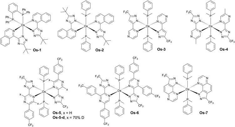
Some of the earlier examples of these complexes have been presented by Chi, Chou and Wu in 2009.85 The authors reported complexes displaying λEL = 718 nm, ηext = 2.7% for Os-1 and λEL = 814 nm, ηext = 1.5% for Os-2 in vacuum-deposited OLED devices. Following this work there have been several new reports published since 2019 featuring novel Os(II) complexes based on a similar concept. For example, Jen, Lee, and Chi explored the most promising mode of coordination, using two monodentate dimethylphenylphosphine ligands, as in Os-2, instead of the chelating diphosphine ligand used in Os-1. They also replaced the pirydyl azolate ligand for a more electron-deficient pyrazinyl azolate, which resulted in a higher OLED performance of complexes emitting around λEL ∼ 700 nm. Hence, complex Os-3, for example, displays λEL = 739 nm and ηext = 5.2%, while complex Os-4λEL = 710 nm and ηext = 11.5% in OLED devices – a significant improvement over complex Os-1.86 The molecular design based on the two axial dimethylphenylphosphine ligands has been reproduced by Chi and collaborators in following works as the most promising design strategy for osmium(II) complexes emitting beyond 700 nm.
Another promising modification of osmium(II) complexes proposed by Su, Zhu, and Chi is replacing some of the hydrogen atoms in the organic ligands for deuterium and using a deuterated OLED host, which leads to reduced non-radiative decay rates.87 The authors reported complexes Os-5 and Os-5-d as well as Os-6. In a non-deuterated CBP Os-5 achieved λEL = 776 nm and ηext = 3.10%, while its deuterated counterpart Os-5-d gave λEL = 776 nm and ηext = 3.77%. When the authors used partly deuterated CBP-d the OLED efficiency of Os-5 was similar, at ηext = 3.09%, but that of Os-5-d increased to ηext = 3.96%. Os-6 gave λEL = 794 nm and ηext = 2.94% in regular CBP.
Most recently, Chi and Lee have achieved λEL = 811 nm with ηext = 0.97% in complex Os-7 where the ‘usual’ pyrazinyl pyrazole chelating ligand is fused into a pyrazolo[3,4-f]quinoxaline unit, resulting in a significant red shift in respect to the complex featuring the former, non-fused unit.88
To sum up, the main design strategy for NIR-emissive osmium(II) complexes appears to be increasing the strength of the metal–ligand charge transfer by stabilisation of the LUMO orbital of the complex. This is done by increasing electron-deficient character of chelating ligands. Osmium(II) complexes are no longer a curiosity in the field, as in recent years they became an important competitor to NIR-luminescent complexes of other metals, such as platinum(II) or iridium(III). Their broadband luminescence spectra are reminiscent of those presented by aggregate platinum(II) complexes, but they are able to attain λEL > 800 nm from isolated molecules and without aggregation or use of high emitter loads.
5. TADF emitters
Donor–acceptor molecular emitters
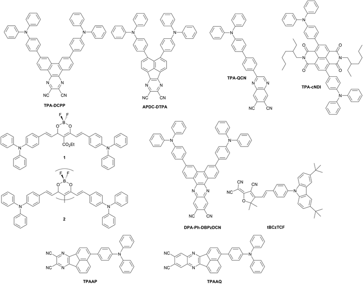
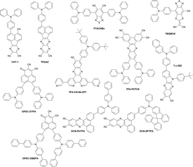
Twisted donor–acceptor (D–A) type organic compounds showing TADF properties are one of the most widely studied NIR-OLED emitters so far (Fig. 16 and 18 as well as Table 5). Charge-transfer (CT) from the donor to the acceptor in the excited state causes a significant perturbation in the electronic and geometrical structure of the D–A molecule, thus resulting in a large Stokes shift. Furthermore, the HOMO and LUMO of a twisted D–A system localizes on the donor and acceptor, respectively, thus achieving a narrow singlet–triplet energy splitting in the excited state (ΔEST). Small ΔEST is a prerequisite for efficient reverse intersystem crossing (RISC) along with a large spin–orbit coupling (SOC) between singlet and triplet states.90–92 By taking the leverage of these features, twisted D–A systems are a promising scaffold for achieving both TADF as well as luminescence in NIR region without using excessively large π-conjugated systems. Furthermore, the twisted D–A geometry impacts packing structure in the solid state where close π⋯π contacts are inhibited to suppress aggregation-caused quenching (ACQ) while J-aggregate formation is induced by electrostatic interactions, leading to a red shifted emission in the condensed phase.| Molecule | λ EL , nm | η ext , % | OLED architecturec | Source |
|---|---|---|---|---|
| a EL maxima. b Maximum external quantum efficiency. c We direct readers to the source articles for explanation of non-common acronyms used in describing OLED architectures. | ||||
| TPA-DCPP | 710 | 2.10 | ITO/TCTA/TPA-DCPP/TPBi/LiF/Al | 93 |
| APDC-DTPA | 777 | 2.20 | ITO/MoO3/NPB/TCTA/APDC-DTPA/TPBi/Liq/Al | 94 |
| APDC-DTPA | 710 | 7.80 | ITO/HAT-CN/TAPC/TCTA/10% APDC-DTPA:Zn(BTZ)2/TPBi/Liq/Al | 95 |
| TPA-QCN | 733 | 3.90 | ITO/NPB/mCP/TPA-QCN/B3PyMPM/LiF/Al | 96 |
| TPA-cNDI | 740 | 2.40 | ITO/NPB/TAPC/10% TPA-cNDI in CBP/TPBi/PO-T2T/LiF/Al | 97 |
| 1 | 721 | 9.70 | ITO/PEDOT:PSS/1 in CBP/DPEPO/TPBi/LiF/Al | 98 |
| 2 | 760 | 5.10 | ITO/PEDOT:PSS/2 in CBP/DPEPO/TPBi/LiF/Al | 99 |
| DPA-Ph-DBPzDCN | 708 | 5.53 | ITO/NPB/TCTA/20% DPA-Ph-DBPzDCN:mCPPy2PO/B3PymPm/Bepp2/LiF/Al | 100 |
| tBCzTCF | 715 | 0.30 | ITO/PEDOT:PSS/PVK/tBCzTCF/DPEPO/TmPyPB/Liq/Al | 101 |
| TPAAP | 700 | 14.10 | ITO/HAT-CN/NPB/TCTA/15% TPAAP:TPBi/TPBi/LiF/Al | 102 |
| TPAAP | 765 | 5.10 | ITO/HAT-CN/NPB/TCTA/TPAAP/TPBi/LiF/Al | 102 |
| TPAAQ | 711 | 3.50 | ITO/HAT-CN/NPB/TCTA/TPAAQ/TPBi/LiF/Al | 102 |
| CAT-1 | 904 | 0.019 | ITO/TAPC/CAT-1/TPBi/LiF/Al | 103 |
| TPAAZ | 1010 | 0.003 | ITO/HAT-CN/TAPC/TCTA/TPAAZ/B3PYMPM/LiF/Al | 104 |
| TPACNBz | 712 | 6.57 | ITO/PEDOT:PSS/NPB/30% TPACNBz:CBP/TmPyPB/LiF/Al | 105 |
| TPA-PZTCN | 734 | 13.40 | ITO/HAT-CN/TAPC/TPA-PZTCN:mCBP/T2T/BPy-TP2/Liq/Al | 106 |
| TPA-CN-N4-2PY | 712 | 21.90 | ITO/MoO3/TAPC/mCP/9% TPA-CN-N4-2PY:mCPCN/3TPYMB/LiF/Al | 107 |
| TBSMCN | 750 | 14.30 | ITO/PEDOT:PSS/PCAQC0.5:TBSMCN:mCP (20![[thin space (1/6-em)]](https://www.rsc.org/images/entities/char_2009.gif) : :![[thin space (1/6-em)]](https://www.rsc.org/images/entities/char_2009.gif) 50 50![[thin space (1/6-em)]](https://www.rsc.org/images/entities/char_2009.gif) : :![[thin space (1/6-em)]](https://www.rsc.org/images/entities/char_2009.gif) 30)/DPEPO/TmPyPB/Liq/Al 30)/DPEPO/TmPyPB/Liq/Al |
108 |
| TBSMCN | 804 | 2.20 | ITO/PEDOT:PSS/TBSMCN/DPEPO/TmPyPB/Liq/Al | 108 |
| T-β-IQD | 711 | 9.90 | ITO/HAT-CN/TAPC/TCTA/T-β-IQD/Liq/Al | 109 |
| DCN-PhTPA | 708 | 17.1 | ITO/HAT-CN/TAPC/TCTA/20% DCN-PhTPA:CBP/TmPyPB/LiF/Al | 110 |
| DCN-SPTPA | 716 | 24.0 | ITO/HAT-CN/TAPC/TCTA/20% DCN-SPTPA:CBP/TmPyPB/LiF/Al | 110 |
| DCN-PhTPA | 780 | 1.78 | ITO/HAT-CN/TAPC/TCTA/DCN-PhTPA/TmPyPB/LiF/Al | 110 |
| DCN-SPTPA | 800 | 2.61 | ITO/HAT-CN/TAPC/TCTA/DCN-SPTPA/TmPyPB/LiF/Al | 110 |
| OPDC-DTPA | 834 | 0.46 | ITO/PEDOT:PSS/PVK/10% OPDC-DTPA:CBP/TmPyPB/LiF/Al | 111 |
| OPDC-DBBPA | 846 | 0.38 | ITO/PEDOT:PSS/PVK/10% OPDC-DBBPA:CBP/TmPyPB/LiF/Al | 111 |
| OPDC-DTPA | 882 | 0.08 | ITO/PEDOT:PSS/PVK/40% OPDC-DTPA:CBP/TmPyPB/LiF/Al | 111 |
| OPDC-DBBPA | 906 | 0.10 | ITO/PEDOT:PSS/PVK/40% OPDC-DBBPA:CBP/TmPyPB/LiF/Al | 111 |
In 2015, Wang et al. reported a purely organic TADF NIR emitter TPA-DCPP, which has a V-shaped D–π–A–π–D configuration having triphenylamines (TPAs) as the D–π units and 2,3-dicyanopyrazino phenanthrene (DCPP) as the acceptor.93 Although diluted solution of TPA-DCPP displays only prompt fluorescence with a nanosecond lifetime, its neat (100%) film exhibits TADF in the NIR region (λem = 708 nm) with a high PLQY (0.14). TPA-DCPP displays a small ΔEST value of 0.13 eV and a microsecond TADF lifetime at room temperature (τTADF = 0.76 μs). It should be noted that a non-doped multilayer OLED exhibited NIR EL at λEL = 710 nm and ηext = 2.1%. The maximum EQE was higher, up to 9.8% in a TPBi host matrix, but at the cost of shorter wavelength which would fall outside of the NIR region.
In 2017, Jiang, Liao and others utilized a dicyano-substituted acenaphthylene unit (acenaphtho[1,2-b]pyrazine-8,9-dicarbonitrile: APDC) as the acceptor core to build D–π–A–π–D configuration (APDC-DTPA).94 Due to the stronger electron-withdrawing character of APDC when compared with DCPP, APDC-DTPA exhibits a more red-shifted TADF (λem = 756 nm) with a higher PLQY (0.17) in a neat film when compared with TPA-DCPP. The non-doped OLED device using APDC-DTPA as the emitting material shows NIR TADF with λEL = 777 nm and ηext = 2.2%. APDC-DTPA dispersed in a host matrix (10% in TPBi), shows λEL = 693 nm and ηext = 10.2%, higher than in neat film, but at the cost of shorter wavelength EL. A follow-up study on the solid-state solvation effect of host materials on emission property conducted by the same group revealed that in a more polar metal-containing host Zn(BTZ)2 (dipole moment = 4.35 D) APDC-DTPA displays NIR PL at ∼700 nm.95 By leveraging this red-shifted behaviour, the authors optimized the device structure and realized a NIR TADF OLED, which displayed NIR emission (λEL = 710 nm) achieving a high ηext = 7.8%.
A simpler D–π–A compound having a triphenylamine (TPA) donor and quinoxaline-6,7-dicarbonitrile (QCN) acceptor, developed by Wang et al., displays NIR TADF (λem = 733 nm) in neat film.96 The compound adopts slightly twisted conformation in the crystal, where the rod-shaped molecular structures are connected with each other through CN⋯H–C and N⋯H–C contacts. The non-doped OLED device achieved a relatively high efficiency (λEL = 733 nm) with ηext = 3.9%. The EL of TPA-QCN can be tuned by varying the emitter load in the host matrix (TPBi), such as at 15% load λEL = 644 nm and ηext = 14.5%, while at 30% load λEL = 700 nm and ηext = 9.4%.
A donor–π–acceptor–π–donor (D–π–A–π–D) type organic compound TPA-cNDI, having naphthalene diimide as an acceptor core and triphenylamine as π-linked donors displays CT PL in the NIR region (λem ∼ 750 nm) in toluene.97 In a non-polar polymeric host matrix (Zeonex), the compound displays prompt fluorescence (τpromt = 1.2 ns) and distinct TADF (τTADF = 10 μs) at around 700 nm. Changing the host matrix from Zeonex to CBP allows significant red-shift in PL to λem ∼ 750 nm. The authors investigated the involvement of triplet excited states in the emission process through quasi-CW (quasi continuous-wave) photo-induced absorption technique. The OLED device showed NIR EL (λEL ∼ 740 nm) with a ηext = 2.4% and radiant emittance of 2.7 mW cm−2.
In 2018, D’Aléo, Ribierre, Adachi and co-workers developed a solution-processable NIR TADF emitter 1 based on a D–π–A–π–D boron difluoride curcuminoid structure.98 The compound 1 is readily synthesized in a one-pot process involving complexation of ethyl diacetoacetate with BF3 and the subsequent aldol-condensation with arylaldehyde. Boron complex 1 displays a varied NIR emission depending on the concentration in CBP host, from λem = 706 to 782 nm. The authors suggest the reason for the high PLQY of 1 (0.70) in CBP film is a significant HOMO–LUMO overlap. The significant red shift occurring as a function of concentration in 1 can be explained by (i) change in polarity of films due to the high ground state dipole moment of the emitter (7–8 Debye) and (ii) aggregation. Time-resolved spectroscopic analysis revealed the existence of dual pathways of NIR TADF emission from monomer and dimer in CBP blend film. OLEDs fabricated with 1 display NIR TADF with λEL = 721 nm and relatively high ηext ∼ 10% with 6% doping. The high efficiency in TADF is explained by a nonadiabatic coupling effect operating between low lying excited states. Interestingly, 1 was applied to NIR lasing. Amplified spontaneous emission (ASE) of 1 in CBP blend film (6%) was clearly observed at λem = 747 nm with a very narrow full-width at half-maximum (FWHM) of 17 nm. The authors have also reported emitter 2 having a dimeric structure of difluoride curcuminoid motif. 2 showed a lower ηext = 5.1% than 1, but a red-shifted EL at 6% load in CBP blend λEL = 774 nm.99 The authors also reported ASE from 2 at 40% load in CBP with emission at λem = 860 nm (Fig. 17).
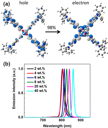 | ||
| Fig. 17 (a) NTOs describing the S1 state of 2. (b) ASE spectrum of 2 in different concentrations. Adapted with permission from ref. 99 Copyright 2018 American Chemical Society. | ||
Ye, Wang and co-workers reported a D–π–A–π–D compound DPA-Ph-DBPzDCN that is composed of dibenzo[a,c]phenazine-11,12-dicarbonitrile (DBPzDCN) as the acceptor, diphenylamine (DPA) as the donor, and phenylene (Ph) as the linker.100 This compound is a π-extended analogue of TPA-DCPP. When compared to TPA-DCPP, DPA-Ph-DBPzDCN displayed a significantly red shifted PL in toluene (λem = 588 nm for TPA-DCPPvs. λem = 618 nm for DPA-Ph-DBPzDCN) and neat film (λem = 708 nm for TPA-DCPPvs. λem = 765 nm for DPA-Ph-DBPzDCN). The OLED device fabricated with DPA-Ph-DBPzDCN showed NIR EL (λEL = 708 nm) with ηext = 5.5%.
A solution-processable NIR TADF emitter tBCzTCF was developed by Han, Xu and co-workers in 2019.101 A non-aromatic electron-accepting unit (2-dicyanomethylene-3-cyano-4,5,5-trimethyl-2,5-dihydrofurane: TCF) was connected with a π–D unit through condensation with 4-carbazolylbenzaldehyde to yield tBCzTCF. The compound is readily soluble in popular organic solvents such as chloroform, chlorobenzene, and DMF. Through the presence of a vinylene–phenylene unit, S1 and T1 states have mixed nature of CT and locally excited states. Non-doped solution-processed OLED device gave λEL = 715 nm and ηext = 0.3%.
Peng, Qiao et al. developed J-aggregate systems of D–A compounds TPAAP and TPAAQ that have acenaphtho[1,2-b]pyrazine-8,9-dicarbonitrile (AP) and acenaphtho[1,2-b]quinoxaline-8,9-dicarbonitrile (AQ) as the acceptor, respectively, and tripheylamine (TPA) as the donor.102 These molecules form J-aggregate dimers in single crystals, having slipping angles of 32.8° and 31.7°, respectively, which are much smaller than the threshold angle of 54.7°. The close intermolecular plane distances are also rather short (3.37 Å and 3.41 Å, respectively). As a proof of high propensity for J-aggregate formation, these compounds display significant red-shift in absorption and photoluminescence as a function of doping ratio in the TPBi blend film. For example, TPAAP displays PL at λem = 597 nm in 0.1% doped film which red-shifts to λem = 705 nm with 15% load and further to λem = 777 nm in a neat film. Accordingly, the S1 state energy is reduced at higher emitter load with only a small reduction in T1 energy. This change of S1 energy was explained by the authors with synergistic effects gained by J-aggregates, van der Waals interaction, and self-polarization-induced solid-state dipole moments. The OLED devices fabricated with TPAAP and TPAAQ display NIR electroluminescence. For example, devices using 15% load of TPAAP give λEL = 700 nm and ηext = 14.1%, while a non-doped OLED using TPAAP yields λEL = 765 nm and ηext = 5.1%. Doped devices using TPAAQ display λEL < 700 nm, but the non-doped OLEDs using TPAAQ show λEL = 711 nm and ηext = 3.5%. Theoretical calculations suggest that the S1 state is a mix of the J-type Frenkel exciton (FE) and charge-transfer exciton (CTE). J-Aggregates appear to be a powerful approach for NIR TADF emitters as they allow for simultaneously achieving red-shifted absorption/emission, significant transition dipole moment, and small ΔEST.
In 2019, Congrave, Bronstein and co-workers developed a D–A emitter CAT-1 (Fig. 19) by replacing a D–π unit of APDC-DTPA with an electron-withdrawing group (CN), achieving a highly red-shifted emission in neat film over 900 nm.103 A significant red-shifted PL spectrum was reported for solution-processed neat film of CAT-1, λem = 950 nm, and a slightly blue shifted PL in an evaporated neat film, λem = 887 nm. Although the TADF mechanism in a neat film is not unambiguously confirmed, CAT-1 is attractive for achieving highly red-shifted NIR luminescence. The fully evaporated OLED using neat film of CAT-1 displays long wavelength NIR EL, λEL = 904 nm, with a relatively low ηext = 0.02%.
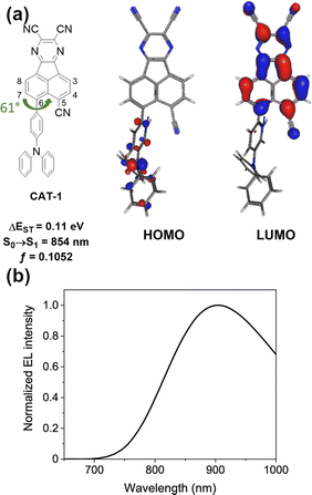 | ||
| Fig. 19 (a) The HOMO and LUMO of CAT-1. (b) EL spectrum of the non-doped OLED fabricated with CAT-1. Adapted with permission from ref. 103 Copyright 2019 American Chemical Society. | ||
Xue, Qiao and co-workers reported a NIR-II (1000–1700 nm) OLED by developing a new D–A emitter TPAAZ, which has two more sp2 N atoms than in the TPAAQ skeleton (Fig. 16).104 Single crystal analysis indicates that the molecules interact with each other through multiple non-covalent bonds such as C–H⋯N, CN⋯π, C–H⋯π, and C–H⋯H–C in short distances (Fig. 20). The introduction of two additional sp2 N atoms into TPAAQ structure significantly lowers the LUMO by 0.7 eV, leading to the lower HOMO–LUMO gap. Also, the PL emission peak of TPPAZ is significantly more red-shifted (λem = 742 nm) than that of TPPAQ (λem = 609 nm) in toluene. In a similar manner with TPPAQ, TPPAZ displays red-shift of emission as a function of concentration of TPPAZ in blend film. It should be noted that the compound shows NIR-II emission over 1000 nm (λem = 1009 nm) in neat film. The QM/MM calculations suggested that the dimer formation can reduce the energy level of excited states through intermolecular CT. A non-doped OLED device achieved NIR-II emission, λEL = 1010 nm, with a modest ηext = 0.003%.
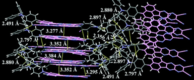 | ||
| Fig. 20 Packing structure of TPAAQ in the single crystal. Reproduced from ref. 104 with permission from the Royal Society of Chemistry. | ||
Promarak and co-workers utilized dicyano-substituted benzothiadiazole electron-acceptor in a NIR-emissive D–A–D compound TPACNBz.105 Due to the highly stabilized LUMO level (−3.63 eV), the compound exhibits pronounced NIR TADF based on intramolecular charge-transfer character in the excited state (λem = 750 nm in neat film). The OLED device fabricated with the emitter exhibits NIR EL, λem = 712 nm, with ηext = 6.57%.
Nakanotani, Tsuchiya, Adachi and co-workers have developed a highly electron-deficient acceptor cored V-shaped D–π–A–π–D molecule TPA-PZTCN comprising triphenylamines as D–π units and dibenzo[a,c]phenazine-2,3,6,7-tetracarbonitrile (PZTCN) as the A unit.106TPA-PZTCN displays a deep LUMO level of −3.84 eV, evident of highly electron deficient nature of the PZTCN unit. The 10%-doped film in mCBP matrix displays NIR TADF at λem = 729 nm with a high PLQY (0.41). The OLED device fabricated with the emitter displays NIR EL, λEL = 734 nm, with a relatively high ηext = 13.4%. The emitter is also utilized as a sensitizer for a NIR fluorescent emitter, giving λEL = 901 nm with ηext = 1.1%.
In 2022, Wang, Wu, Fan et al. developed NIR-TADF emitter TPA-CN-N4-2PY, which comprises a D–π–A1–A2–A3 structure, where diarylamine serves as a D–π unit, cyano group serves as A1, dipyrido[3,2-a:2′,3′-c]phenazine serves as A2, and two pyridines serve as the A3 component.107 The extended coplanar π system in the acceptor (A1–A2–A3) allows for enhancing horizontal ratio of emitting dipole orientation (Θ‖), leading to enhanced optical out-coupling efficiency (Φout) up to 41%. As the results, the OLED fabricated with TPA-CN-N4-2PY achieved a very high EQE up to ηext = 21.9% with λEL = 712 nm.
Xie, Zhao, Tang, and co-workers have developed a series of D–π–A compounds having a new electron deficient acceptor, cyano-substituted dithiafulvalene-fused benzothiadiazole (BSMCN).108 One of the representatives of this family, TBSMCN, has a diphenylamine donor and displays AIE characteristics. The neat film of TBSMCN displays NIR emission at λem = 820 nm with a high PLQY (0.11), and the emission is significantly red-shifted in the crystalline state, presumably due to the formation of dimers. The highly electron deficient nature of the acceptor is confirmed by cyclic voltammetry (HOMO/LUMO = −5.05/−3.65 eV). By utilizing the AIE character, the solution-processed OLED device fabricated with TBSMCN showed NIR EL, λEL = 804 nm, with a relatively high ηext = 2.2%, which corresponds to a very high exciton utilization efficiency (EUE) of 81.1%. It should be noted that a higher ηext = 14.3% with λEL = 750 nm was achieved by making use of a ternary emissive system {host (mCP)/emitter (TBSMCN)/sensitizer (PCAQC0.5) = 3/5/2} as the emitting layer.
Li, Ge et al. designed and developed a new D–π–A type compound T-β-IQD that has a 6-(4-(tert-butyl)phenyl)-6H-indolo[2,3-b]quinoxaline-2,3-di-carbonitrile (IQD) as the electron acceptor and N,N-diphenylnaphthalen-2-amine (β-TPA) as the donor.109 The molecule displays AIE behaviour and forms distinct J-aggregates in the crystalline state. MD and DFT calculations reveal that the J-aggregates can form even in the amorphous state, where efficient intermolecular charge transfer occurs. In addition to the formation of J-aggregates, restriction of intramolecular rotations (RIR) and vibrations (RIV) through intra- and intermolecular non-covalent interactions allows suppression of non-radiative decay. As a result, the non-doped OLED device fabricated with T-β-IQD as the emitter achieved NIR EL (λem = 711 nm) with a very high EQE (9.4%).
Wang, Zhang et al. developed NIR emitters based on the known dibenzo[a,c]phenazine-11,12-dicarbonitrile, but with modified triphenylamine donors to study the effect of intermolecular interactions on OLED efficiency.110 The new emitters, DCN-PhTPA and DCN-SPTPA display high efficiency in OLEDs with doped emissive layers at 20% doping: λEL = 708 nm with ηext = 17.1% in DCN-PhTPA and λEL = 716 nm with ηext = 24.0% in DCN-SPTPA as well as neat emissive layers: λEL = 780 nm with ηext = 1.78% in DCN-PhTPA and λEL = 800 nm with ηext = 2.61% in DCN-SPTPA. The authors highlight the role of the molecular geometry on intermolecular interactions and the resultant concentration quenching. In particular, the DCN-SPTPA with a spirobifluorene unit attached to the donor displays a higher overall OLED EQE and lower sensitivity of OLED efficiency on emitter load than DCN-PhTPA. Furthermore, the former displays a higher EQE in neat films despite a longer wavelength EL, which can be owed to weakening of the intermolecular interactions in film with the bulky spirobifluorene unit.
Dang, Su, Zhu, Liu and co-workers have recently reported a new type of acceptor for NIR-TADF materials, 1-oxo-1-phenalene-2,3-dicarbonitrile (OPDC) with a LUMO energy of ca. −3.3 eV that allows for long wavelength electroluminescence close to 900 nm.111 The authors introduced two new NIR TADF emitters with a donor–acceptor structure: OPDC-DTPA and OPDC-DBBPA which display toluene PL beyond 800 nm. The OLED λEL varies with emitter concentration in a range from 824 to 906 nm. Representative OLED performance at 10% load are: λEL = 834 nm and ηext = 0.46% for OPDC-DTPA, and λEL = 846 nm and ηext = 0.38% for OPDC-DBBPA, while at 40% load these values are λEL = 882 nm and ηext = 0.08% for OPDC-DTPA, and λEL = 906 nm and ηext = 0.1% for OPDC-DBBPA.
Exciplex emitters
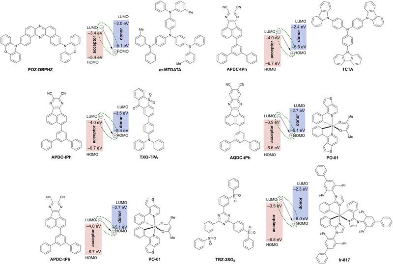
Exciplex is an excited state complex formed between a molecule in the excited state and another molecule in the ground state through intermolecular charge transfer (Fig. 21 and Table 6). Since the hole and electron are localized exclusively on the donor and acceptor molecule, respectively, a small ΔEST is expected to realize and accelerate RISC from the triplet excited state to the singlet excited state. Therefore, exciplex formation is a promising strategy for TADF with a significantly red shifted emission. Exciplex-based TADF OLEDs have been intensively studied112 since Adachi et al. demonstrated the utilization of exciplex TADF in an efficient OLED device to harvest electrically generated triplet excitons.113 To realize efficient exciplex formation, there are many factors to be considered such as the adjustment of the HOMO and LUMO levels of D and A moieties, confinement of excitons by local excited states of constituent molecules to avoid energy leakage, and charge balance in the emissive layer. Due to the intrinsic factors that influence the photophysics of exciplexes, designing exciplex NIR TADF emitters for OLED devices is a challenging task. Thus, not surprisingly, there are very few reports of exciplexes being used as the emitter in NIR TADF OLEDs.| Exciplex | λ EL , nm | η ext , % | OLED architecturec | Source |
|---|---|---|---|---|
| a EL maxima. b Maximum external quantum efficiency. c We direct readers to the source articles for explanation of non-common acronyms used in describing OLED architectures. | ||||
| POZ-DBPHZ:m-MTDATA | 741 | ∼5 | ITO/m-MTDATA/POZ-DBPHZ:m-MTDATA/TPBi/LiF/Al | 114 |
| APDC-tPh:TCTA | 730 | 0.09 | ITO/MoO3/NPB/TCTA/APDC-tPh:TCTA (1![[thin space (1/6-em)]](https://www.rsc.org/images/entities/char_2009.gif) : :![[thin space (1/6-em)]](https://www.rsc.org/images/entities/char_2009.gif) 1)/B4PYMPM/Liq/Al 1)/B4PYMPM/Liq/Al |
115 |
| APDC-tPh:TXO-TPA | 704 | 1.24 | ITO/MoO3/NPB/TCTA/APDC-tPh:TXO-TPA (1![[thin space (1/6-em)]](https://www.rsc.org/images/entities/char_2009.gif) : :![[thin space (1/6-em)]](https://www.rsc.org/images/entities/char_2009.gif) 1)/B4PYMPM/Liq/Al 1)/B4PYMPM/Liq/Al |
115 |
| AQDC-Ph:PO-01 | 750 | 0.23 | ITO/MoO3/TAPC/AQDC-Ph:PO-01 (15%)/DPEPO/B3PyMPM/Liq/Al | 116 |
| APDC-Ph:PO-01 | 824 | 0.16 | ITO/MoO3/TAPC/APDC-tPh:PO-01 (15%)/DPEPO/B3PyMPM/Liq/Al | 116 |
| TRZ-3SO2:Ir-817 | 746 | 0.20 | ITO/TAPC/m-MTDATA/TRZ-3SO2:Ir-817 (8![[thin space (1/6-em)]](https://www.rsc.org/images/entities/char_2009.gif) : :![[thin space (1/6-em)]](https://www.rsc.org/images/entities/char_2009.gif) 2)/TPBi/LiF/Al 2)/TPBi/LiF/Al |
117 |
The driving force for charge separation (−ΔGCS) is the key factor to form exciplexes. According to the modified Rehm–Weller equation, −ΔGCS in the solid state is expressed by the following equation:118
| –ΔGCS = Eexcitation (EA* or ED*) − Eexciplex | (1) |
| Eexciplex = hνem ≈ e(EDox − EAred) + C | (2) |
 | (3) |
A first example of a NIR TADF exciplex was reported by Data, Takeda et al. in 2016.114 The authors developed a donor–acceptor–donor (D–A–D) type TADF emitter POZ-DBPHZ for efficient OLED devices. While the OLED device fabricated with POZ-DBPHZ in CBP host emits orange TADF (λELca. 615 nm), the OLED fabricated with a blend POZ-DBPHZ:m-MTDATA displays NIR emission (λEL = 741 nm) with a relatively high ηext at ca. 5% for exciplex-based NIR OLEDs – at the time comparable with other classes of NIR OLED luminophores.
Jiang, Liao et al. reported exciplex NIR TADF emitters by developing a new acceptor APDC-tPh.115 The APDC-tPh is featured with a significantly low LUMO (−3.95 eV), which couples with the HOMO of the donor molecule. While the neat film of APDC-tPh displays greenish photoluminescence (λPL = 510 nm), the 1![[thin space (1/6-em)]](https://www.rsc.org/images/entities/char_2009.gif) :
:![[thin space (1/6-em)]](https://www.rsc.org/images/entities/char_2009.gif) 1 blended film of APDC-tPh:TCTA shows NIR TADF (λPL = 720 nm). The S1 energy (1.72 eV) of the exciplex is visibly lower than that of the constituent materials (S1/T1 of APDC-tPh = 2.84/2.11 eV; S1/T1 of TCTA = 3.09/2.72 eV), which is important for efficient exciplex formation and TADF. The OLED device fabricated with the exciplex forming blend at 1
1 blended film of APDC-tPh:TCTA shows NIR TADF (λPL = 720 nm). The S1 energy (1.72 eV) of the exciplex is visibly lower than that of the constituent materials (S1/T1 of APDC-tPh = 2.84/2.11 eV; S1/T1 of TCTA = 3.09/2.72 eV), which is important for efficient exciplex formation and TADF. The OLED device fabricated with the exciplex forming blend at 1![[thin space (1/6-em)]](https://www.rsc.org/images/entities/char_2009.gif) :
:![[thin space (1/6-em)]](https://www.rsc.org/images/entities/char_2009.gif) 1 ratio in the emissive layer displays NIR EL (λEL = 730 nm) with a rather modest ηext = 0.09%. To improve the EQE, the authors used a bipolar (D–A type) TADF emitter TXO-TPA as the donor. Using a 1
1 ratio in the emissive layer displays NIR EL (λEL = 730 nm) with a rather modest ηext = 0.09%. To improve the EQE, the authors used a bipolar (D–A type) TADF emitter TXO-TPA as the donor. Using a 1![[thin space (1/6-em)]](https://www.rsc.org/images/entities/char_2009.gif) :
:![[thin space (1/6-em)]](https://www.rsc.org/images/entities/char_2009.gif) 1 blend of APDC-tPh:TXO-TPA in the OLED device allows improving the efficiency to ηext = 1.27% and a low efficiency roll-off, showing NIR TADF luminescence at λEL = 704 nm. The use of bipolar TADF molecule as donor components in exciplexes provides conditions to generate multiple RISC channels to harvest electrically generated triplet excitons. As a result, the ηext can be improved relative to using only unipolar components.
1 blend of APDC-tPh:TXO-TPA in the OLED device allows improving the efficiency to ηext = 1.27% and a low efficiency roll-off, showing NIR TADF luminescence at λEL = 704 nm. The use of bipolar TADF molecule as donor components in exciplexes provides conditions to generate multiple RISC channels to harvest electrically generated triplet excitons. As a result, the ηext can be improved relative to using only unipolar components.
Recently, Liao et al. developed a new acceptor AQDC-tPh, which is a π-extended version of APDC-tPh, and used it in conjunction with a commercially-available iridium(III) complex PO-01 to form a NIR-emitting exciplex.116AQDC-Ph has similar HOMO/LUMO energy levels (−6.6/−3.9 eV) with those of APDC-tPh. Using a transition metal complex as a donor in an exciplex is a less common approach than that based solely on heavy metal-free materials. Involving HOMO of the Ir(III) centre and LUMO of the acceptor potentially benefits both triplet harvesting and RISC, thanks to the large spin–orbit coupling (SOC) induced by the metal centre. The blend film AQDC-Ph:PO-01 (x%) shows NIR TADF, and the λPL red-shifts from 727 to 752 nm as a function of doping ratio (from x = 5 to 25). The doping ratio also influences the luminescent decay lifetime of the blend. The authors report distinct prompt ∼100 ns and TADF ∼ 400–800 ns lifetimes, however the decay traces shown could also be interpret as the biexponential TADF decay. These exciplexes are likely not to display any significant prompt fluorescence due to the presence of a heavy atom, as it happens in some metalorganic TADF luminophores.119 Nevertheless, we believe exciplexes incorporating transition metal complexes display an interesting set of properties and their photophysics is yet to be fully understood. OLED device fabricated with the exciplex emitting layer displays NIR EL (λEL = 750 nm) with a modest ηext = 0.23%. The use of the APDC-tPh (15%) acceptor in a similar device structure allows for a more red-shifted emission (λEL = 824 nm) with a relatively good ηext = 0.16% for a such long-wavelength EL.
Similarly to the previous work, Zheng, Zhang et al. reported a NIR-emissive exciplex from a blend of an iridium complex Ir-817, serving as a donor and triazine-cored sulfone compound TRZ-3SO2 as the acceptor.117 The OLED fabricated with the blend emitting layer TRZ-3SO2:Ir-817 displays NIR TADF (λEL = 746 nm) with a modest ηext = 0.2%.
MR-TADF emitters
A new molecular approach to TADF materials was presented by Hatakeyama et al. in 2015,120 named multiple resonance TADF in the follow-up work,121 while currently a term multiresonance TADF (MR-TADF) is used. Their molecular design involves an alternating HOMO/LUMO pattern based on complimentary resonance effects of electron-donating oxygen/nitrogen and electron-withdrawing boron moieties. Thanks to the rigid structure of their luminophores and a somewhat local character of the emissive singlet states the authors observed narrowband emission. This opened the possibility to realize efficient OLED emitters demonstrating high colour purity and TADF characteristics at the same time, one of the biggest challenges to date.Following these initial works, over 200 MR-TADF materials have been reported, most of which show blue and green emission. We refer the readers to a vast collection of reviews in this topic.71,122–124 MR-TADF materials show short-range charge transfer between adjacent atoms and decorating MR-TADF core with peripheral donor groups has shown to result in emission tuning. However, when significantly strong donor groups are employed the lowest excited states lose the short-range charge transfer character responsible for the narrowband emission. They instead display conventional, long-range CT emissive excited state that is typically observed in D–A TADF compounds discussed in the previous sections.
Given the scarcity of MR-TADF emitters in the red/NIR region we discuss the most remarkable examples of luminophores covering longer wavelength range of the visible spectrum.
For example, Zhang et al.125 have designed a highly twisted carbazole-fused DABNA derivative that displays ηext up to 39% with λEL at 588 nm. The highly twisted structure helped to relieve concentration quenching, allowing the development of devices with doping ratio as high as 8%, unusual for this class of materials. To the best of our knowledge, the MR-TADF materials that showed emission closest to the NIR region while retaining low FWHM were the R-BN and R-TBN (Fig. 22) developed by Duan et al.126 By adopting B-phenyl-B and N-phenyl-N structures with mutually ortho-positioned B and N atoms, they reduced the emission energy gap and eliminated nonradiative transitions by suppressing vibration coupling due to the shallow potential energy surface induced by the MR effect. The deep red emitters, R-BN and R-TBN, showed high PLQY of 100% and their use in OLEDs resulted in λEL at 664 nm and 686 nm with FWHMs below 50 nm and maximum ηext of 28%. The authors used a phosphorescent sensitiser and the device structure in this case was: ITO/TAPC/TCTA/3% R-BN/R-TBN:Ir(mphmq)2tmd:CBP (3![[thin space (1/6-em)]](https://www.rsc.org/images/entities/char_2009.gif) :
:![[thin space (1/6-em)]](https://www.rsc.org/images/entities/char_2009.gif) 7)/CzPhPy/B4PyMPM/LiF/Al.
7)/CzPhPy/B4PyMPM/LiF/Al.
MR-TADF materials have mostly been explored for blue and green luminescence, while producing red/NIR emissive examples remains challenging. Thus, the establishment of a simple molecular design strategy to realize NIR emission while maintaining good colour purity for MR-TADF emitters is a challenge yet to be resolved.
6. Fluorescent emitters
Most popular classes of NIR emitting organic dyes include BODIPYs (also aza-BODIPYs), cyanine, rylene dyes,127 as well as bisbenzo-C-rhodamine based dyes modified with a diphenyl ether moiety through spiro linkage referred to as EXE dyes.128 D–A–D129 dyes also allow tuning of the energy gap in order to afford NIR emission. An interesting concept is the use of luminophores incorporating oligomeric thiophene130 or metal porphyrin units.131 Examples of NIR fluorescent dyes discussed in this review are presented in Fig. 23 while the pertinent OLED characteristics are shown in Table 7. What makes the fluorescent dyes attractive is that they are characterized by relatively narrow absorption and emission bands, typically high molar absorption coefficients, and moderate to high fluorescence quantum yields.19,132 In 2019 Hu, Ma, Ma and others reported an NIR-emitting fluorescent molecule with λEL = 840 nm in OLED, but no ηext value was presented by the authors.133 Some recent efforts have also exploited dimer formation (squaraine dyes being used amongst others) in order to achieve NIR emission.31,134 Rylenes have also been exploited as NIR emitters with longer lifetimes hence they are more attractive for bioimaging applications.127 The family of rylene dyes includes PDI, TDI and QDI. With each naphthalene unit added a red shift of approximately 100 nm is expected. There have been reports in the literature of pentarylene with absorption maximum of 877 nm and hexarylenebis(dicarboximide) with absorption maximum of about 950 nm. All of the above mentioned rylene chromophores are characterised by narrow absorption and emission bands with mirror symmetry. For more details on this class of dyes we refer the reader to an excellent review by Weil et al.127| Emitter | λ EL , nm | η ext , % | OLED architecturec | Source |
|---|---|---|---|---|
| a EL maxima. b Maximum external quantum efficiency. c We direct readers to the source articles for explanation of non-common acronyms used in describing OLED architectures. | ||||
| I-P6(THS) | 850 | 1.50 | ITO/PEDOT:PSS/2.5% I-P6(THS):F8BT/Ca/Al | 131 |
| TBtz1 | 702 | 1.52 | ITO/PEDOT:PSS/30% Tbtz1:CBP/TPBi/LiF/Al | 130 |
| TBtz2 | 723 | 1.22 | ITO/PEDOT:PSS/30% Tbtz2:CBP/TPBi/LiF/Al | 130 |
| TBtz1 | 734 | 0.48 | ITO/PEDOT:PSS/Tbtz1/TPBi/LiF/Al | 130 |
| TBtz2 | 773 | 0.26 | ITO/PEDOT:PSS/Tbtz2/TPBi/LiF/Al | 130 |
| PBTPA | 656 | 1.62 | ITO/HAT-CN/TAPC/PBTPA/TmPyPB/LiF/Al | 139 |
| B3 | 632 | 1.01 | ITO/PEDOT:PSS/0.5% B3:PhCz-4CzTPN/TPBi/Cs2CO3/Al | 140 |
| BDP-C-Cz | 602 | 19.25 | ITO/PEDOT:PSS/0.9% BDP-C-Cz: 13% 4CzIPN:CBP/PPF/TmPyPB/CsF/Al | 141 |
| TTDSF | 774 | 5.30 | ITO/HAT-CN/TAPC/7% TTDSF:DPSF:CN-T2T (50![[thin space (1/6-em)]](https://www.rsc.org/images/entities/char_2009.gif) : :![[thin space (1/6-em)]](https://www.rsc.org/images/entities/char_2009.gif) 50)/CN-T2T/LiF/Al 50)/CN-T2T/LiF/Al |
142 |
Another avenue for achieving NIR emission from organic chromophores is J-coupling/aggregation.135,136 J-aggregates are such in which the transition dipole moments are aligned in slip-stacked alignment as opposed to parallel arrangement or plane-to plane stacking to form a sandwich-type arrangement (H-dimer).137 Such aggregates exhibit red shifted emission when compared to the parent chromophore. Synthesising J-dimers of known chromophores can also lead to emission in the NIR region as exemplified by Shen et al. with squaraine dyes31 and Li et al. with BODIPY dyes.138 Li et al. have carried out in vivo lymph node imaging during fluorescence-guided surgery in the nude mouse. This is an excellent demonstration of the potential of such aggregates. The meso-[2.2]paracyclophanyl-3,5-bis-N,N-dimethylaminostyrl BODIPY referred to as PCP-BDP2 shows fluorescence emission at 1010 nm. As ever the aggregation induced fluorescence quenching means that the PLQYs for these materials are relatively low, in case of PCP-BDP2 it is only 6.4% (1010 nm).
Some of the more interesting examples of the use of fluorescent dyes in NIR OLEDs include fluorescent zinc porphyrin oligomers.131 Cacialli, Anderson, and others have developed an intriguing structure where the porphyrin units are connected in series through acetylide linkers. This design provides conjugation between the linked zinc porphyrines, resulting in a significant photoluminescence red shift from λPL = 630 nm for a single porphyrin to λPL = 800 nm for a hexameric structure. The authors reported an OLED device using the hexameric I-P6(THS), which displays λEL = 850 nm and a maximum ηext = 3.8% which was recorded at ∼1 μA. For the purpose of this review we consider the value of ηext = 1.5% recorded at ∼10 μA as more reliable.
Pomarak et al. developed donor–acceptor–donor type fluorescent emitters featuring oligothiophene fragments: TBtz1 and TBtz2 (Fig. 24).130 These emitters display λEL in the range of 700–780 nm either dispersed in CBP or in neat film. The authors reported that TBtz1 and TBtz2 doped in CBP matrix display ηext = 1.52% with λEL = 702 nm, and ηext = 1.22% with λEL = 723 nm, respectively. TBtz1 and TBtz2 in neat emissive layers display more red shifted EL: ηext = 0.48% with λEL = 734 nm, and ηext = 0.26% with λEL = 773 nm, respectively.
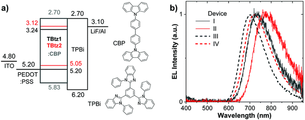 | ||
| Fig. 24 (a) OLED device structure and (b) EL spectra for TBtz1 (black lines) and TBtz2 (red lines). Reproduced from ref. 130 with permission from the Royal Society of Chemistry. | ||
Another avenue to achieving red emitting fluorophores for optoelectronic purposes is aggregated induced emission (AIE).143,144 Molecules like PBTPA have been used for OLED fabrication. Unfortunately, the EQE values have been low, ηext = 1.62% (λEL = 656 nm).139 However, it promises a new avenue for investigations.
Another example is series of purpose designed BODIPYs with PhCz-4CzTPN as TADF sensitiser published by Ma et al., where the highest EQE reported was ηext = 1.0% (λEL = 632 nm) for B3-D1 device.140 Low EQEs are characteristic of organic fluorophore based devices, especially these based on BODIPYs or any other planar fluorophores. For BODIPYs the small Stokes’ shifts and planar structure can cause quenching.145 Additionally, just like any other fluorophore they are only able to harvest 25% of the excitons generated in an OLED. However, BODIPYs have been applied with a lot more success for Hyperfluorescence (HF) based OLED devices.146–148 HF devices rely on the Förster Energy Transfer from TADF donor to a fluorescent dopant. In theory this process can utilise the efficiency of TADF devices and improve on it. It also allows for harnessing the benefits of fluorescent materials like the narrow emission bands (small FWHM). Importantly, it helps the device stability by decreasing the exciton related degradation which is induced by the long triplet exciton lifetime. TADF sensitisers used in NIR HF OLEDs are presented in Fig. 25. Jung et al. published an example of 4CzTPN HF device using BODIPY as the energy acceptor with EQEs up to 19.4% (617 nm).149 This was improved on recently by Nie et al., where they have developed a BODIPY emitter with a bipolar donor–acceptor–donor (D–A–D) structure, BDP-C-Cz, synthesised by affixing a carbazole donor to the BODIPY core from the different positions. This resulted in orange-to-red emission with hybridized local and charge-transfer characteristics. The fabricated HF OLED devices with BDP-C-Cz showed excellent performance with ηext = 19.25% at luminance of 1000![[thin space (1/6-em)]](https://www.rsc.org/images/entities/char_2009.gif) cd
cd![[thin space (1/6-em)]](https://www.rsc.org/images/entities/char_2009.gif) m−2, an electroluminescence peak at λEL = 602
m−2, an electroluminescence peak at λEL = 602![[thin space (1/6-em)]](https://www.rsc.org/images/entities/char_2009.gif) nm, and a small FWHM of 63
nm, and a small FWHM of 63![[thin space (1/6-em)]](https://www.rsc.org/images/entities/char_2009.gif) nm characteristic of the BODIPY dyes.141 These devices unfortunately are not yet NIR emitting, however it is a significant progress for red fluorescent OLEDs.
nm characteristic of the BODIPY dyes.141 These devices unfortunately are not yet NIR emitting, however it is a significant progress for red fluorescent OLEDs.
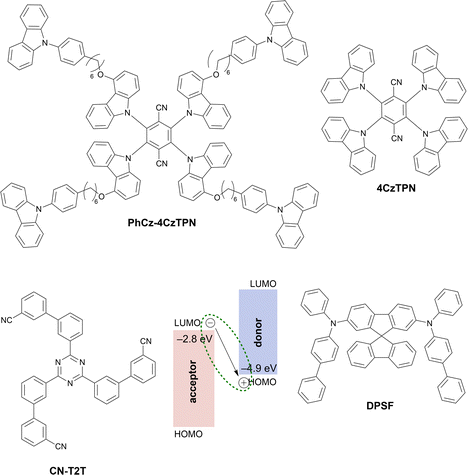 | ||
| Fig. 25 Examples of TADF sensitisers used with fluorescent deep red/NIR terminal emitters in hyperfluorescent OLEDs. | ||
Another example of the HF-TADF approach to OLED was presented by Wong, Liu et al. who used a TADF exciplex host.142 Their best result employed DPSF:CN-T2T exciplex as a host for TTDSF NIR fluorescent dye. The authors reported an OLED with ηext = 5.3% and electroluminescence peak at λEL = 774![[thin space (1/6-em)]](https://www.rsc.org/images/entities/char_2009.gif) nm. The TTDSF luminophore does not display the narrowband luminescent profile typical for hyperfluorescent OLEDs, nevertheless it is an interesting example for the use of efficient NIR fluorophores in OLEDs.
nm. The TTDSF luminophore does not display the narrowband luminescent profile typical for hyperfluorescent OLEDs, nevertheless it is an interesting example for the use of efficient NIR fluorophores in OLEDs.
Overall, it is clear that despite some favourable properties, fluorescent materials are not desirable materials for NIR OLEDs due to fundamental issues associated with the energy gap law and the ability to only harvest 25% of the excitons. In addition, they are often planar molecules prone to aggregation which further complicates their use for OLED device fabrication. Nevertheless, NIR fluorescent emitter design is an interesting area of research, that has many other potential applications in bioimaging and optical communications, amongst other things.
7. Radical emitters
Different from the closed-shell molecules discussed earlier in this review, luminescent radicals are open-shell species. This means they have unpaired electrons in non-bonding singly occupied molecular orbitals (SOMOs) that are energetically in between the highest occupied and lowest unoccupied molecular orbitals (HOMO and LUMO). The unpaired electron results in doublet-spin multiplicity and these molecules have both ground (D0) and lowest excited states (D1) as doublets, with D1–D0 transition being spin-allowed. These systems can also form dark quartet states (Q1), which are analogous to the dark triplets in closed-shell species. However, quartet states are located above the doublet states and therefore do not play a significant role in OLEDs since these higher-energy electronic states would internally convert to the lower-energy D-type excited states (Fig. 26). For more in-depth details on doublet states and emission mechanisms, we suggest ref. 150–153. To sum up, radicals eliminate the problem of 'dark' triplet formation observed in closed shell molecules and present new avenues for the development of OLEDs with IQE up to 100%. Moreover, doublets show fast, nanosecond emission lifetimes, another desirable feature for OLEDs, as fast radiative decay is expected to alleviate issues related with device operational lifetimes.154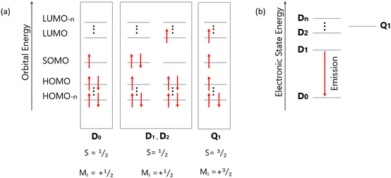 | ||
| Fig. 26 (a) Molecular orbital diagrams for a doublet emitter showing electron occupancy in ground state (D0) and excited states (D1, D2, and Q1). (b) Jablonski energy diagrams of the doublet–quartet manifold, indicating doublet–doublet fluorescence. Adapted from ref. 152, with the permission of AIP Publishing. | ||
TTM radical based materials
Triphenylmethyl (TTM)155 based radicals are the most broadly investigated class of luminescent radicals, largely because of TTM's thermal and chemical stability, and well-known synthetic methodology (Fig. 27, 28 and Table 8). To tune emission colour, luminescence performance and electrochemical properties, different aromatic donor groups have been introduced into the TTM core. In 2006 Gamera et al.156 designed and synthesized TTM-1Cz by incorporating carbazole into TTM radical, which exhibited intense intramolecular charge transfer state formation indicated by red fluorescence emission in cyclohexane (λPL = 628 nm) compared to carbazole (λPL = 334/350 nm) and TTM (λPL = 563 nm) emissions. However, only in 2015 Peng et al.157 utilized TTM-1Cz as emitter in devices, reporting the first OLED showing doublet emission. In this work, TTM-1Cz was doped into CBP host to prevent aggregation-caused quenching, and the resultant devices showed λEL = 692 nm and ηext up to 2.4%. Following works successively designed new TTM-based molecules with emission spectra at longer wavelengths, enhanced luminescence efficiency and stability. This was achieved by incorporation of substituent groups with strong electron donating ability as well as restricting the rotation of the outer groups.158–160 However, these materials fully attracted interest from the OLED community when in 2018 Ai et al.161 reported radical based OLEDs with ηext as high as 27%. They developed TTM-3NCz and TTM-3PCz by incorporating 3-substituted-9-(naphthalen-2-yl)-9H-carbazole (3NCz) and 3-substituted-9-phenyl-9H-carbazole (3PCz) to the TTM core. OLEDs using TTM-3NCz achieved maximum ηext values of 27% (λEL = 710 nm) and using TTM-3PCzηext = 17% (λEL = 710 nm). It is worth to note though that these high EQE values were achieved at impractically low current densities (<10 μA cm−2). Nevertheless, TTM-3NCz-based devices represent some of the highest ηext reported to date for deep-red/NIR OLEDs. Considering the scope of this review, we limit the following discussion to the most recent works that successfully developed radical materials showing emission wavelengths close or above 700 nm and explored their use in devices.| Emitter | λ EL , nm | η ext , % | OLED architecturec | Source |
|---|---|---|---|---|
| a EL maxima. b Maximum external quantum efficiency. c We direct readers to the source articles for explanation of non-common acronyms used in describing OLED architectures. | ||||
| TTM-1Cz | 692 | 2.4 | ITO/NPB/CBP/5% TTM-1Cz:CBP/TPBi/LiF/Al | 157 |
| TTM-3NCz | 710 | 27.0 | ITO/MoO3/TAPC/3% TTM-3NCz:CBP/B3PYMPM/PO-T2T/LiF/Al | 161 |
| TTM-3PCz | 710 | 17.0 | ITO/MoO3/TAPC/3% TTM-3PCz:CBP/B3PYMPM/PO-T2T/LiF/Al | 161 |
| TTM-3PDMAC | 830 | 3.1 | ITO/MoO3/TAPC/5% TTM-3PDMAC:CBP/B3PYMPM/PO-T2T/LiF/Al | 158 |
| TTM-PDMAC | 760 | 2.7 | ITO/MoO3/TAPC/5% TTM-PDMAC:CBP/B3PYMPM/PO-T2T/LiF/Al | 158 |
| PS-CzTTM | 685 | 3.0 | ITO/PEDOT:PSS/PVK/10–15% PS-CzTTM:TPBi/B3PYMPM/LiF/Al | 163 |
| SQ-BP:TTM-1Cz | 690 | 8.0 | ITO/MoO3/TAPC/2% SQ-BP:TTM-1Cz/PO-T2T/LiF/Al | 164 |
| PTM-3NCz | 700 | 5.0 | ITO/PEDOT:PSS/PVK/PTM-3NCz:TPBi/B3PYMPM/LiF/Al | 166 |
Ding et al.158 explored an isomeric strategy for obtaining efficient NIR luminescent radicals, they incorporated 9,9-dimethyl-10-phenyl-9,10-dihydroacridine (PDMAC) with different linking positions to the TTM core, developing TTM-3PDMAC and TTM-PDMAC. TTM-3PDMAC exhibited a red shift and slightly higher luminescence efficiency compared to its isomeric counterpart TTM-PDMAC, because of its more planar conformation, larger extent of conjugation and stronger intramolecular charge transfer character. OLEDs based on TTM-3PDMAC achieved ηext = 3.1% (λEL = 830 nm) and TTM-PDMACηext = 2.7% (λEL = 760 nm).
Moving to larger molecules, second, third and fourth-generation carbazole dendronized TTM radicals have been explored by Albrecht et al.162 (Fig. 28). Their photophysical properties demonstrated that the enlargement of the dendrons greatly improves the PLQY of the radicals from G2TTM to G4TTM together with the hypsochromic shift of the emission in the series G2TTM–G4TTM, λPL at 795 nm, 764 nm, and 729 nm, respectively, in toluene. This behaviour arises from the decrease in the electron–electron repulsion in the occupied orbitals on the dendron fragment, as shown through calculations. OLED devices were not presented in this work, however the authors state that further work involving OLEDs is ongoing.
Furthermore, Gu et al.163 designed PS-CzTTM, which was synthesized by attaching CzTTM pendants to the polymeric backbone of polystyrene (PS). They reported solution processed OLEDs with ηext = 3% and λEL = 685 nm, opening the possibility to use low-cost fabrication methods for radical based OLEDs.
Moreover, the use of TTM based radicals as sensitizers has been explored by Chen et al.164 (Fig. 29). Using this route, electrons and holes first recombine on the radical molecule creating doublet excitons, then through energy transfer singlet excitons are generated on the fluorescent dye, where emission takes place. SQ-BP:TTM-1Cz devices showed ηext up to 8% (λEL ∼ 690 nm), suggesting that OLEDs using conventional fluorescent dyes as terminal emitters can also show 100% IQE through the luminescent radical sensitizing route.
 | ||
| Fig. 29 (a) Schematic diagram for the sensitizing processes. DR stands for doublet radiation, FR for fluorescence radiation, and ET for energy transfer. (b) EL spectra of the devices with different doping ratio. (c) External quantum efficiency versus current density with different doping ratio. Adapted with permission from ref. 164 Copyright 2019 American Chemical Society. | ||
PTM radical based materials
Perchlorotriphenylmethyl (PTM)165 radical has also been a centre of attention as an acceptor unit in the design of new radical emitters for OLEDs. Compared to TTM, PTM possesses six additional chlorine atoms, which makes it unsuitable for vacuum evaporation due to the potential loss of some of the chlorines upon heating at vacuum. However, they have been explored in solution processed devices.Guo et al.166 have combined PTM with various donor groups and chose to explore the use of PTM-3NCz as the emitter in solution processed OLEDs (ηext ∼ 5%, λEL = 700 nm). However, interestingly, they observed that the Aufbau principle (vide infra) could be violated if the donor groups introduced to the PTM displayed a rather strong electron-donating ability. Breaking the Aufbau principle means that the energy of the singly occupied SOMO level (localized on the PTM) is lower than that of the HOMO level (localized on the donor group). This is clearly an unusual energy alignment. The non-Aufbau behaviour reduces chemical activity of the single electron, leading to materials with excellent photostability. It should be noted though that this was not the first observation of the non-Aufbau behaviour.167,168
Other works successively reported new PTM-based molecules and the impact of molecular structure on photostability, emission wavelength, fluorescence yield, and molecular rigidity was explored by incorporation of different substituent groups.169–171
There is no doubt that radical-based OLEDs overcome the spin-statistical limitations of traditional fluorescent OLEDs. However, we recognize that the research of radical-based OLEDs is at its infancy and their potential is still not yet fully realized. Most of the materials mentioned above show high decay rates with the radiative lifetimes in the range of nanoseconds, and high PLQY values. Thus, we expect realization of OLEDs showing higher ηext values and much less severe OLED efficiency roll-off than currently observed. We believe that attention towards understanding the underlying mechanisms of electrical excitation in these complex systems is critical to improve device performance.
8. Conclusions and perspectives
In this work we have reviewed a wide range of NIR luminescent molecules: platinum(II), iridium(III), and osmium(II) complexes, TADF emitters: intra- and intermolecular CT systems and MR-TADF structures, fluorescent dyes, and luminescent radicals. Some of these groups appear to be gaining much more interest than the others: mainly platinum(II) complexes and TADF emitters. The former are valued for their uncontested high efficiency in NIR, and the latter for the possibility to achieve reasonably efficient NIR OLEDs without transition metals.What becomes clearly apparent is that metalorganic luminophores generally outperform other types of NIR-luminescent systems. Or at least platinum(II) complexes evidently do so. At the same time metalorganic emitters often display reasonably good roll-off and hence their efficiency is high even at higher current densities.
Radical (doublet) emitters present a clearly promising category of NIR luminophores which, at least theoretically, will be able to once and for all resolve the problem of spin statistics in OLEDs. While there is a lot of promise in these materials, the research is clearly at its infancy and the problems faced by luminescent radicals are yet to be resolved. We should closely follow the developments in this area but remain cautious to what extent luminescent radicals can actually satisfy the requirements for a stable NIR OLED emitter. The current research focuses on the TTM and PTM type radicals, but they may not be the final form of radicals used in OLED. We are expecting that novel design of stable radicals will emerge in the future and trigger a true breakthrough in this subject.
We observe growing evidence for the role of heavy atoms in reducing non-radiative decay of NIR emitters, such as through deuterated and iodinated complexes presented above. It perhaps may be a hint to why transition metal complexes generally outperform other types of NIR OLED emitters. The heavy atoms present in the structure may not only be promoting radiative phosphorescent decay, but also significantly contribute to damping selected vibrational modes of the NIR luminophores, in turn reducing non-radiative deactivation. Although at this point we can only speculate, this issue is definitely a matter deserving an in-depth study. Deuteration or otherwise inclusion of heavier analogues of atoms and groups in NIR luminophores may be a way to increase the efficiency in some cases, but may not be the ultimate solution for the problem.
Aggregation is perhaps the most efficient way to achieve long wavelength OLED EL and the most stereotypical examples of such approach are platinum(II) complexes. Due to the planar structure of these complexes, their aggregation is reasonably well understood and relatively easy to study. In turn, aggregation of D–A molecules, such as that observed in NIR-luminescent TADF systems is much more difficult to study. Further development in this area is clearly necessary to better understand the behaviour and predict the properties of NIR-emitting TADF aggregates.
We observe a clear predominance of broadband NIR emitters presenting dominating charge-transfer character of the emission, such as Pt(II) aggregates (3MMLCT) or intramolecular CT TADF emitters. More narrowband NIR emitters are currently in minority as the focus is on realising efficiency records at increasingly longer EL wavelengths. Authors of this review recall similar trends dominating among visible light OLED emitters a few years ago, with CT-TADF emitters dominating at first.172,173 Currently the focus in the TADF field is concentrated around narrowband MR-TADF luminophores,71,121 and we expect a similar future of the NIR OLED field. However, unlike for visible light TADF emitters, there is little indication for the MR-TADF systems to be of any significance in the near future. It appears that producing narrow energy gaps in these systems may be challenging and may not be resolved for the time being. In terms of narrowband (or at least more narrowband) NIR emitters the most promising at the moment are luminescent complexes of iridium(III) and platinum(II), which display MLCT + LC excited state character. NIR HF-TADF systems also give some promise, but their current state of development is insufficient to outcompete the currently most efficient groups of luminophores.
OLED ηext and λEL for all NIR emitters presented in this review are shown in Fig. 30. The results are presented with the logarithmic external quantum efficiency axis to better visualise the differences between reports in the longer wavelength region – this is, for λEL > 800 nm, where the best reported efficiencies do not exceed ∼10%. It is apparent that majority of reported NIR OLEDs display EL maxima shorter than 800 nm, leaving the 800–1000 nm region of the electromagnetic spectrum with relatively few examples. We propose existence of an apparent NIR boundary line, a diagonal line of the form presented in eqn (4) which appears to be the current limitation for most NIR OLEDs except for metal complexes with rigid, planar structure, and radicals. The region below the line is composed of all types of emitters without a distinction, but the region above the line is virtually dominated by platinum(II) complexes. The exact definition of this line may become more clear once more emitters with λEL > 800 nm are reported, however it appears to be describing a somewhat general trend in relation to NIR OLED efficiency. Importantly, there appears to be no distinction between metal-free and metalorganic (non-platinum) emitters, indicating that, perhaps, TADF systems may be bound by the same limitations as iridium(III) or osmium(II) complexes. In other words, we may speculate that iridium(III) or osmium(II) complexes as well as TADF emitters produce similar NIR OLED efficiency, without a clear superiority of either of these groups. On the other side, monomeric and aggregating platinum(II) complexes appear not to be bound by the limitations set out by the boundary. Some of the reported examples in fact display efficiencies 1–2 orders of magnitude higher than best platinum-free counterparts with similar λEL.
| ηlim = a·eb·λEL | (4) |
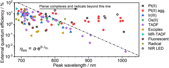 | ||
| Fig. 30 Relationship between OLED external quantum efficiency and electroluminescence peak wavelength for the highest efficiency NIR emitters. Examples of state-of-the-art perovskite/quantum dot LEDs are shown for readers’ reference.175–178 | ||
One Zn(II) porphyrin complex and one radical emitter also appear above the line. This may be an indication that the rigid structure of porphyrin complexes promotes NIR luminescence in a more general way. On the other hand, perhaps the different luminescent mechanism governing luminescent radicals offers some benefits in terms of reducing non-radiative decay. There are currently too few examples to clearly identify the reasons for this behaviour as this might simply be a one-off fluctuation.
Although NIR LEDs are not the focus of this review, they pose a perfect comparison for NIR OLEDs. Some prominent examples of such devices are presented in Fig. 30 alongside OLED efficiencies. Generally speaking, NIR LEDs display similar or superior efficiencies to aggregate platinum(II) complexes. They are however bound by the limitations related to the use of luminescent nanoparticles in OLEDs. The topic is discussed further in a separate review.174
In summary, the NIR boundary line clearly indicates some kind of limitation that can easily be overcome by planar, rigid metal complexes. Intuitively, we may expect there being some benefit of those rigid molecular architectures in terms of non-radiative decay. Clearly, the mostly planar structure of these complexes reduces the available degrees of freedom for vibrations, resulting in some modes being suppressed. This matter definitely deserves a further study which we hope will be triggered through this review.
Our findings suggest that, perhaps, there is currently no future in NIR OLEDs without platinum.
In conclusion, although the research of novel NIR luminophores has been going on for many years, it remains an ever increasing topic. Perhaps many hope that we will be able to remove transition metal complexes from OLEDs once and for all, however there is no indication in sight that this will happen in the nearest future. The research on novel metal-based emitters is ongoing and there are no real competitors to NIR-emissive platinum(II) complexes as of today. This trend may continue for years to come. Clearly, there is an apparent advantage which these complexes provide over other NIR luminophores.
We wish for further developments in the field and hope the next few years will bring a plethora of new efficiency and long wavelength breakthroughs. Perhaps at one point we will reach the true limitations of luminescent electronic transitions in producing NIR light. If once we discover a long wavelength NIR emitter with near unity photoluminescence quantum yield then it will likely be a platinum(II) complex.
Author contributions
P. L. D. S., P. S., Y. T: investigation, conceptualization, visualization, writing – original draft, writing – review & editing; P. P.: investigation, conceptualization, visualization, writing – original draft, writing – review & editing, data curation, project administration, funding acquisition, formal analysis.Data availability
Our supporting research data is available from the Durham Research Online DATAsets Archive (DRO-DATA) open data repository. DOI: https://doi.org/10.15128/r23r074t97g.Conflicts of interest
There are no conflicts to declare.Acknowledgements
P. P. thanks the National Science Centre, Poland for funding, grant No. 2022/47/D/ST4/01496. P. S. acknowledges support from the Royal Society University Research Fellowship URF\R1\221121.Notes and references
- J. G. Bünzli and S. V. Eliseeva, Lanthanide NIR luminescence for telecommunications, bioanalyses and solar energy conversion, J. Rare Earths, 2010, 28, 824–842 CrossRef.
- M. Vasilopoulou, A. Fakharuddin, F. P. García de Arquer, D. G. Georgiadou, H. Kim, A. R. bin Mohd Yusoff, F. Gao, M. K. Nazeeruddin, H. J. Bolink and E. H. Sargent, Advances in solution-processed near-infrared light-emitting diodes, Nat. Photonics, 2021, 15, 656–669 CrossRef CAS.
- A. Zampetti, A. Minotto and F. Cacialli, Near-Infrared (NIR) Organic Light-Emitting Diodes (OLEDs): Challenges and Opportunities, Adv. Funct. Mater., 2019, 29, 1807623 CrossRef.
- A. K. East, M. Y. Lucero and J. Chan, New directions of activity-based sensing for in vivo NIR imaging, Chem. Sci., 2021, 12, 3393–3405 RSC.
- J. Huang and K. Pu, Near-infrared fluorescent molecular probes for imaging and diagnosis of nephro-urological diseases, Chem. Sci., 2021, 12, 3379–3392 RSC.
- Y. Liu, W. Hou, L. Xia, C. Cui, S. Wan, Y. Jiang, Y. Yang, Q. Wu, L. Qiu and W. Tan, ZrMOF nanoparticles as quenchers to conjugate DNA aptamers for target-induced bioimaging and photodynamic therapy, Chem. Sci., 2018, 9, 7505–7509 RSC.
- R. Englman and J. Jortner, The energy gap law for radiationless transitions in large molecules, Mol. Phys., 1970, 18, 145–164 CrossRef CAS.
- Y.-C. Wei, S. F. Wang, Y. Hu, L.-S. Liao, D.-G. Chen, K.-H. Chang, C.-W. Wang, S.-H. Liu, W.-H. Chan, J.-L. Liao, W.-Y. Hung, T.-H. Wang, P.-T. Chen, H.-F. Hsu, Y. Chi and P.-T. Chou, Overcoming the energy gap law in near-infrared OLEDs by exciton–vibration decoupling, Nat. Photonics, 2020, 14, 570–577 CrossRef CAS.
- G. R. Suman, M. Pandey and A. S. J. Chakravarthy, Review on new horizons of aggregation induced emission: from design to development, Mater. Chem. Front., 2021, 5, 1541–1584 RSC.
- J. Mei, Y. Hong, J. W. Y. Lam, A. Qin, Y. Tang and B. Z. Tang, Aggregation-induced emission: The whole is more brilliant than the parts, Adv. Mater., 2014, 26, 5429–5479 CrossRef CAS PubMed.
- M. Cocchi, J. Kalinowski, D. Virgili and J. A. G. Williams, Excimer-based red/near-infrared organic light-emitting diodes with very high quantum efficiency, Appl. Phys. Lett., 2008, 92, 113302 CrossRef.
- D. N. Kozhevnikov, V. N. Kozhevnikov, M. Z. Shafikov, A. M. Prokhorov, D. W. Bruce and J. A. G. Williams, Phosphorescence vs Fluorescence in Cyclometalated Platinum(II) and Iridium(III) Complexes of (Oligo)thienylpyridines, Inorg. Chem., 2011, 50, 3804–3815 CrossRef CAS PubMed.
- S. Zhen, S. Wang, S. Li, W. Luo, M. Gao, L. G. Ng, C. C. Goh, A. Qin, Z. Zhao, B. Liu and B. Z. Tang, Efficient Red/Near-Infrared Fluorophores Based on Benzo[1,2-b:4,5-b′]dithiophene 1,1,5,5-Tetraoxide for Targeted Photodynamic Therapy and In Vivo Two-Photon Fluorescence Bioimaging, Adv. Funct. Mater., 2018, 28, 1706945 CrossRef.
- J. Maillard, C. A. Rumble and A. Fürstenberg, Red-Emitting Fluorophores as Local Water-Sensing Probes, J. Phys. Chem. B, 2021, 125, 9727–9737 CrossRef CAS PubMed.
- N. Shimomura, Y. Egawa, R. Miki, T. Fujihara, Y. Ishimaru and T. Seki, A red fluorophore comprising a borinate-containing xanthene analogue as a polyol sensor, Org. Biomol. Chem., 2016, 14, 10031–10036 RSC.
- W.-T. Chuang, B.-S. Chen, K.-Y. Chen, C.-C. Hsieh and P.-T. Chou, Fluorescent protein red Kaede chromophore; one-step, high-yield synthesis and potential application for solar cells, Chem. Commun., 2009, 6982 RSC.
- C. Micheletti, Q. Wang, F. Ventura, M. Turelli, I. Ciofini, C. Adamo and A. Pucci, Red-emitting tetraphenylethylene derivative with aggregation-induced enhanced emission for luminescent solar concentrators: a combined experimental and density functional theory study, Aggregate, 2022, 3, e188 CrossRef CAS.
- R. Ziessel, G. Ulrich and A. Harriman, The chemistry of Bodipy: A new El Dorado for fluorescence tools, New J. Chem., 2007, 31, 496 RSC.
- G. Ulrich, R. Ziessel and A. Harriman, The Chemistry of Fluorescent Bodipy Dyes: Versatility Unsurpassed, Angew. Chem., Int. Ed., 2008, 47, 1184–1201 CrossRef CAS PubMed.
- A. Loudet and K. Burgess, BODIPY Dyes and Their Derivatives: Syntheses and Spectroscopic Properties, Chem. Rev., 2007, 107, 4891–4932 CrossRef CAS PubMed.
- S. Qi, S. Kim, V.-N. Nguyen, Y. Kim, G. Niu, G. Kim, S.-J. Kim, S. Park and J. Yoon, Highly Efficient Aggregation-Induced Red-Emissive Organic Thermally Activated Delayed Fluorescence Materials with Prolonged Fluorescence Lifetime for Time-Resolved Luminescence Bioimaging, ACS Appl. Mater. Interfaces, 2020, 12, 51293–51301 CrossRef CAS PubMed.
- H. Shi, L. Zou, K. Huang, H. Wang, C. Sun, S. Wang, H. Ma, Y. He, J. Wang, H. Yu, W. Yao, Z. An, Q. Zhao and W. Huang, A Highly Efficient Red Metal-free Organic Phosphor for Time-Resolved Luminescence Imaging and Photodynamic Therapy, ACS Appl. Mater. Interfaces, 2019, 11, 18103–18110 CrossRef CAS PubMed.
- M. Ji and X. Ma, Recent progress with the application of organic room-temperature phosphorescent materials, Ind. Chem. Mater., 2023, 1, 582–594 RSC.
- J. R. Caine, P. Hu, A. T. Gogoulis and Z. M. Hudson, Unlocking New Applications for Thermally Activated Delayed Fluorescence Using Polymer Nanoparticles, Acc. Mater. Res., 2023, 4, 879–891 CrossRef CAS.
- A. Punjabi, X. Wu, A. Tokatli-Apollon, M. El-Rifai, H. Lee, Y. Zhang, C. Wang, Z. Liu, E. M. Chan, C. Duan and G. Han, Amplifying the Red-Emission of Upconverting Nanoparticles for Biocompatible Clinically Used Prodrug-Induced Photodynamic Therapy, ACS Nano, 2014, 8, 10621–10630 CrossRef CAS PubMed.
- Q. Luo, L. Li, H. Ma, C. Lv, X. Jiang, X. Gu, Z. An, B. Zou, C. Zhang and Y. Zhang, Deep-red fluorescence from isolated dimers: a highly bright excimer and imaging in vivo, Chem. Sci., 2020, 11, 6020–6025 RSC.
- Y. Wang, Q. Sun, L. Xie, L. Chen, F. Zhu and L. Liu, BODIPY Dimers with a Fused and Coplanar Structure: Photophysical Comparison, Low Threshold for Amplified Spontaneous Emission, and Deep-Red Bio-Imaging/Photodynamic Therapy Application, ACS Omega, 2023, 8, 28376–28386 CrossRef CAS PubMed.
- M. Ogawa, N. Kosaka, P. L. Choyke and H. Kobayashi, H-Type Dimer Formation of Fluorophores: A Mechanism for Activatable, in Vivo Optical Molecular Imaging, ACS Chem. Biol., 2009, 4, 535–546 CrossRef CAS PubMed.
- Y. Hong, J. W. Y. Lam and B. Z. Tang, Aggregation-induced emission: phenomenon, mechanism and applications, Chem. Commun., 2009, 4332 RSC.
- J. Surre, C. Saint-Ruf, V. Collin, S. Orenga, M. Ramjeet and I. Matic, Strong increase in the autofluorescence of cells signals struggle for survival, Sci. Rep., 2018, 8, 12088 CrossRef PubMed.
- C.-A. Shen, M. Stolte, J. H. Kim, A. Rausch and F. Würthner, Double J-Coupling Strategy for Near Infrared Emitters, J. Am. Chem. Soc., 2021, 143, 11946–11950 CrossRef CAS PubMed.
- Y. Fang, J. Shang, D. Liu, W. Shi, X. Li and H. Ma, Design, Synthesis, and Application of a Small Molecular NIR-II Fluorophore with Maximal Emission beyond 1200 nm, J. Am. Chem. Soc., 2020, 142, 15271–15275 CrossRef CAS PubMed.
- C. Ash, M. Dubec, K. Donne and T. Bashford, Effect of wavelength and beam width on penetration in light-tissue interaction using computational methods, Lasers Med. Sci., 2017, 32, 1909–1918 CrossRef PubMed.
- C. T. Jackson, S. Jeong, G. F. Dorlhiac and M. P. Landry, Advances in engineering near-infrared luminescent materials, iScience, 2021, 24, 102156 CrossRef CAS PubMed.
- K. R. Graham, Y. Yang, J. R. Sommer, A. H. Shelton, K. S. Schanze, J. Xue and J. R. Reynolds, Extended conjugation platinum(II) porphyrins for use in near-infrared emitting organic light emitting diodes, Chem. Mater., 2011, 23, 5305–5312 CrossRef CAS.
- C. Wu, Y. Zhang, J. Miao, K. Li, W. Zhu and C. Yang, Tetradentate cyclometalated platinum complex enables high-performance near-infrared electroluminescence with excellent device stability, Chin. Chem. Lett., 2023, 34, 107445 CrossRef CAS.
- S. Yang, F. Meng, X. Wu, Z. Yin, X. Liu, C. You, Y. Wang, S. Su and W. Zhu, Dinuclear platinum(II) complex dominated by a zig-zag-type cyclometalated ligand: a new approach to realize high-efficiency near infrared emission, J. Mater. Chem. C, 2018, 6, 5769–5777 RSC.
- K. Zhang, Y. Liu, Z. Hao, G. Lei, S. Cui, W. Zhu and Y. Liu, A feasible approach to obtain near-infrared (NIR) emission from binuclear platinum(II) complexes containing centrosymmetric isoquinoline ligand in PLEDs, Org. Electron., 2020, 87, 105902 CrossRef CAS.
- M. Z. Shafikov, P. Pander, A. V. Zaytsev, R. Daniels, R. Martinscroft, F. B. Dias, J. A. G. Williams and V. N. Kozhevnikov, Extended ligand conjugation and dinuclearity as a route to efficient platinum-based near-infrared (NIR) triplet emitters and solution-processed NIR-OLEDs, J. Mater. Chem. C, 2021, 9, 127–135 RSC.
- C. Murawski and M. C. Gather, Emerging Biomedical Applications of Organic Light-Emitting Diodes, Adv. Opt. Mater., 2021, 9, 2100269 CrossRef CAS.
- H. E. Lee, J. H. Shin, J. H. Park, S. K. Hong, S. H. Park, S. H. Lee, J. H. Lee, I. Kang and K. J. Lee, Micro Light-Emitting Diodes for Display and Flexible Biomedical Applications, Adv. Funct. Mater., 2019, 29, 1808075 CrossRef.
- J. Zhi, Q. Zhou, H. Shi, Z. An and W. Huang, Organic Room Temperature Phosphorescence Materials for Biomedical Applications, Chem. – Asian J., 2020, 15, 947–957 CrossRef CAS PubMed.
- A. P. Darmanyan, Generation of 1O2 and the mechanism of internal conversion in 9,10-diphenylanthracene, Chem. Phys. Lett., 1982, 91, 396–400 CrossRef CAS.
- E. Reynoso, A. M. Durantini, C. A. Solis, L. P. Macor, L. A. Otero, M. A. Gervaldo, E. N. Durantini and D. A. Heredia, Photoactive antimicrobial coating based on a PEDOT-fullerene C60 polymeric dyad, RSC Adv., 2021, 11, 23519–23532 RSC.
- T. Hamano, K. Okuda, T. Mashino, M. Hirobe, K. Arakane, A. Ryu, S. Mashiko and T. Nagano, Singlet oxygen production from fullerene derivatives: effect of sequential functionalization of the fullerene core, Chem. Commun., 1997, 21–22 RSC.
- N. Epelde-elezcano, V. Martínez-Martínez, E. Peña-Cabrera, C. F. A. Gómez-Durán, I. L. Arbeloa and S. Lacombe, Modulation of singlet oxygen generation in halogenated BODIPY dyes by substitution at their meso position: towards a solvent-independent standard in the vis region, RSC Adv., 2016, 6(48), 41991–41998 RSC.
- S. K. Attili, A. Lesar, A. McNeill, M. Camacho-Lopez, H. Moseley, S. Ibbotson, I. D. W. Samuel and J. Ferguson, An open pilot study of ambulatory photodynamic therapy using a wearable low-irradiance organic light-emitting diode light source in the treatment of nonmelanoma skin cancer, Br. J. Dermatol., 2009, 161, 170–173 CrossRef CAS PubMed.
- Y. Jeon, I. Noh, Y. C. Seo, J. H. Han, Y. Park, E. H. Cho and K. C. Choi, Parallel-Stacked Flexible Organic Light-Emitting Diodes for Wearable Photodynamic Therapeutics and Color-Tunable Optoelectronics, ACS Nano, 2020, 14, 15688–15699 CrossRef CAS PubMed.
- C. Lian, M. Piksa, K. Yoshida, S. Persheyev, K. J. Pawlik, K. Matczyszyn and I. D. W. Samuel, Flexible organic light-emitting diodes for antimicrobial photodynamic therapy, npj Flex. Electron., 2019, 3, 18 CrossRef.
- F. V. Cabral, C. Lian, S. Persheyev, T. K. Smith, M. S. Ribeiro and I. D. W. Samuel, Organic Light-Emitting Diodes as an Innovative Approach for Treating Cutaneous Leishmaniasis, Adv. Mater. Technol., 2021, 6, 2100395 CrossRef CAS.
- Y. Jeon, H.-R. Choi, M. Lim, S. Choi, H. Kim, J. H. Kwon, K.-C. Park and K. C. Choi, A Wearable Photobiomodulation Patch Using a Flexible Red-Wavelength OLED and Its In Vitro Differential Cell Proliferation Effects, Adv. Mater. Technol., 2018, 3, 1700391 CrossRef.
- Y. Jeon, H.-R. Choi, J. H. Kwon, S. Choi, K. M. Nam, K.-C. Park and K. C. Choi, Sandwich-structure transferable free-form OLEDs for wearable and disposable skin wound photomedicine, Light: Sci. Appl., 2019, 8, 114 CrossRef CAS PubMed.
- M. Cocchi, D. Virgili, V. Fattori, J. A. G. Williams and J. Kalinowski, Highly efficient near-infrared organic excimer electrophosphorescent diodes, Appl. Phys. Lett., 2007, 90, 023506 CrossRef.
- E. Rossi, L. Murphy, P. L. Brothwood, A. Colombo, C. Dragonetti, D. Roberto, R. Ugo, M. Cocchi and J. A. G. Williams, Cyclometallated platinum(II) complexes of 1,3-di(2-pyridyl)benzenes: tuning excimer emission from red to near-infrared for NIR-OLEDs, J. Mater. Chem., 2011, 21, 15501 RSC.
- E. Rossi, A. Colombo, C. Dragonetti, D. Roberto, F. Demartin, M. Cocchi, P. Brulatti, V. Fattori and J. A. G. Williams, From red to near infra-red OLEDs: the remarkable effect of changing from X = –Cl to –NCS in a cyclometallated [Pt(N∧C∧N)X] complex (N∧C∧N = 5-mesityl-1,3-di-(2-pyridyl)benzene), Chem. Commun., 2012, 48, 3182–3184 RSC.
- G. Cheng, Q. Wan, W. H. Ang, C. L. Kwong, W. P. To, P. K. Chow, C. C. Kwok and C. M. Che, High-Performance Deep-Red/Near-Infrared OLEDs with Tetradentate [Pt(O^N^C^N)] Emitters, Adv. Opt. Mater., 2019, 7, 1–7 Search PubMed.
- K. Tuong Ly, R.-W. Chen-Cheng, H.-W. Lin, Y.-J. Shiau, S.-H. Liu, P.-T. Chou, C.-S. Tsao, Y.-C. Huang and Y. Chi, Near-infrared organic light-emitting diodes with very high external quantum efficiency and radiance, Nat. Photonics, 2017, 11, 63–68 CrossRef CAS.
- S. F. Wang, Y. Yuan, Y. Wei, W. Chan, L. Fu, B. Su, I. Chen, K. Chou, P. Chen, H. Hsu, C. Ko, W. Hung, C. Lee, P. Chou and Y. Chi, Highly Efficient Near-Infrared Electroluminescence up to 800 nm Using Platinum(II) Phosphors, Adv. Funct. Mater., 2020, 30, 2002173 CrossRef CAS.
- Y.-C. Wei, S. F. Wang, Y. Hu, L.-S. Liao, D.-G. Chen, K.-H. Chang, C.-W. Wang, S.-H. Liu, W.-H. Chan, J.-L. Liao, W.-Y. Hung, T.-H. Wang, P.-T. Chen, H.-F. Hsu, Y. Chi and P.-T. Chou, Overcoming the energy gap law in near-infrared OLEDs by exciton–vibration decoupling, Nat. Photonics, 2020, 14, 570–577 CrossRef CAS.
- P. Pander, A. Sil, R. J. Salthouse, C. W. Harris, M. T. Walden, D. S. Yufit, J. A. G. Williams and F. B. Dias, Excimer or aggregate? Near infrared electro- and photoluminescence from multimolecular excited states of N^C^N-coordinated platinum(II) complexes, J. Mater. Chem. C, 2022, 10, 15084–15095 RSC.
- R. J. Salthouse, P. Pander, D. S. Yufit, F. B. Dias and J. A. G. Williams, Near-infrared electroluminescence beyond 940 nm in Pt(N^C^N)X complexes: influencing aggregation with the ancillary ligand X, Chem. Sci., 2022, 13, 13600–13610 RSC.
- S.-F. Wang, B.-K. Su, X.-Q. Wang, Y.-C. Wei, K.-H. Kuo, C.-H. Wang, S.-H. Liu, L.-S. Liao, W.-Y. Hung, L.-W. Fu, W.-T. Chuang, M. Qin, X. Lu, C. You, Y. Chi and P.-T. Chou, Polyatomic molecules with emission quantum yields 20% enable efficient organic light-emitting diodes in the NIR(II) window, Nat. Photonics, 2022, 16, 843–850 CrossRef CAS.
- W. Xiong, F. Meng, H. Tan, Y. Wang, P. Wang, Y. Zhang, Q. Tao, S. Su and W. Zhu, Dinuclear platinum complexes containing aryl-isoquinoline and oxadiazole-thiol with an efficiency of over 8.8%: in-depth investigation of the relationship between their molecular structure and near-infrared electroluminescent properties in PLEDs, J. Mater. Chem. C, 2016, 4, 6007–6015 RSC.
- Z. Wen, Y. Xu, X. Song, J. Miao, Y. Zhang, K. Li and C. Yang, Approaching the Shortest Intermetallic Distance of Half-Lantern Diplatinum(II) Complexes for Efficient and Stable Deep-Red Organic Light-Emitting Diodes, Adv. Opt. Mater., 2023, 11, 2300201 CrossRef CAS.
- J. Yu, X. Yang, J. Chen, D. Liu, L. Cao, H. Tan and W. Zhu, Achieving near-infrared electroluminescence around 780 nm based on butterfly-shaped dinuclear platinum(II) complexes, J. Mater. Chem. C, 2023, 11, 12384–12391 RSC.
- S.-Q. Sun, J.-J. Shen, Y.-F. Wang, Y.-T. Jiang, L.-F. Chen, H. Xin, J.-N. Wang, X.-B. Shi, X.-Z. Zhu, Q. Sun, L.-S. Liao, Q. Chen, M.-K. Fung and S.-T. Lee, Red organic light-emitting diodes based photobiomodulation therapy enabling prominent hair growth, Nano Res., 2023, 16, 7164–7170 CrossRef CAS.
- A. Gilhar, A. Etzioni and R. Paus, Alopecia Areata, N. Engl. J. Med., 2012, 366, 1515–1525 CrossRef CAS PubMed.
- J. H. Sim, J. Kwon, H. Chae, S.-B. Kim, H. Cho, W. Lee, S. H. Kim, C.-W. Byun, S. Hahn, D. H. Park and S. Yoo, OLED catheters for inner-body phototherapy: a case of type 2 diabetes mellitus improved via duodenal photobiomodulation, Sci. Adv., 2023, 9, eadh8619 CrossRef CAS PubMed.
- P. P. Manousiadis, K. Yoshida, G. A. Turnbull and I. D. W. Samuel, Organic semiconductors for visible light communications, Philos. Trans. R. Soc. A Math. Phys. Eng. Sci., 2020, 378, 20190186 CrossRef CAS PubMed.
- A. Minotto, P. A. Haigh, G. Łukasiewicz, E. Lunedei, D. T. Gryko, I. Darwazeh and F. Cacialli, Visible light communication with efficient far-red/near-infrared polymer light-emitting diodes, Light: Sci. Appl., 2020, 9, 70 CrossRef PubMed.
- J. M. Ha, S. H. Hur, A. Pathak, J.-E. Jeong and H. Y. Woo, Recent advances in organic luminescent materials with narrowband emission, NPG Asia Mater., 2021, 13, 53 CrossRef CAS.
- M. Z. Shafikov, R. Daniels, P. Pander, F. B. Dias, J. A. G. Williams and V. N. Kozhevnikov, Dinuclear Design of a Pt(II) Complex Affording Highly Efficient Red Emission: Photophysical Properties and Application in Solution-Processible OLEDs, ACS Appl. Mater. Interfaces, 2019, 11, 8182–8193 CrossRef CAS PubMed.
- P. Pander, R. Daniels, A. V. Zaytsev, A. Horn, A. Sil, T. J. Penfold, J. A. G. Williams, V. N. Kozhevnikov and F. B. Dias, Exceptionally fast radiative decay of a dinuclear platinum complex through thermally activated delayed fluorescence, Chem. Sci., 2021, 12(17), 6172–6180 RSC.
- K. Tuong Ly, R. W. Chen-Cheng, H. W. Lin, Y. J. Shiau, S. H. Liu, P. T. Chou, C. S. Tsao, Y. C. Huang and Y. Chi, Near-infrared organic light-emitting diodes with very high external quantum efficiency and radiance, Nat. Photonics, 2017, 11, 63–68 CrossRef CAS.
- D. Kim and J. L. Brédas, Triplet excimer formation in platinum-based phosphors: a theoretical study of the roles of Pt–Pt bimetallic interactions and interligand π–π interactions, J. Am. Chem. Soc., 2009, 131, 11371–11380 CrossRef CAS PubMed.
- J. Xue, L. Xin, J. Hou, L. Duan, R. Wang, Y. Wei and J. Qiao, Homoleptic Facial Ir(III) Complexes via Facile Synthesis for High-Efficiency and Low-Roll-Off Near-Infrared Organic Light-Emitting Diodes over 750 nm, Chem. Mater., 2017, 29, 4775–4782 CrossRef CAS.
- Y. Zhang, Q. Li, M. Cai, J. Xue and J. Qiao, An 850 nm pure near-infrared emitting iridium complex for solution-processed organic light-emitting diodes, J. Mater. Chem. C, 2020, 8, 8484–8492 RSC.
- C. You, D. Liu, M. Zhu, J. Yu, B. Zhang, Y. Liu, Y. Wang and W. Zhu, σ–π and p–π conjugation induced NIR-emitting iridium(III) complexes anchored by flexible side chains in a rigid dibenzo[a,c]phenazine moiety and their application in highly efficient solution-processable NIR-emitting devices, J. Mater. Chem. C, 2020, 8, 7079–7088 RSC.
- C. You, D. Liu, J. Yu, H. Tan, M. Zhu, B. Zhang, Y. Liu, Y. Wang and W. Zhu, Boosting Efficiency of Near-Infrared Emitting Iridium(III) Phosphors by Administrating Their π–π Conjugation Effect of Core–Shell Structure in Solution-Processed OLEDs, Adv. Opt. Mater., 2020, 8, 2000154 CrossRef CAS.
- Z. Chen, H. Zhang, D. Wen, W. Wu, Q. Zeng, S. Chen and W.-Y. Wong, A simple and efficient approach toward deep-red to near-infrared-emitting iridium(III) complexes for organic light-emitting diodes with external quantum efficiencies of over 10%, Chem. Sci., 2020, 11, 2342–2349 RSC.
- X. Chang, K. Lu, S. Zeng, D. Liu, J. Huang, B. Ma, L. Wang, X. Gan, J. Yu, Y. Wang, S. Su and W. Zhu, High-efficiency long-wavelength NIR iridium complexes constructed by extending rigid coordination and optimizing peripheral donor position to break cocoon into butterfly, Chem. Eng. J., 2023, 475, 146031 CrossRef CAS.
- Y. He, G. Fu, W. Li, B. Wang, T. Miao, M. Tan, W. Feng and X. Lü, Efficient near-infrared (NIR) polymer light-emitting diode (PLED) based on the binuclear [(C^N)2Ir-(bis-N^O)-Ir(C^N)2] complex with aggregation-induced phosphorescent enhancement (AIPE) character, J. Lumin., 2020, 218, 116847 CrossRef CAS.
- H. Yersin, Triplet Emitters for OLED Application. Mechanisms of Exciton Trapping and Control of Emission Properties, Top. Curr. Chem., 2004, 1–26 CAS.
- P. Pander, A. Zaytsev, A. Sil, G. Baryshnikov, F. Siddique, J. A. G. Williams, F. B. Dias and V. N. Kozhevnikov, Thermally Activated Delayed Fluorescence in a Deep Red Dinuclear Iridium(III) Complex: a Hidden Mechanism for Short Luminescence Lifetimes, Chem. Sci., 2023, 14(47), 13934–13943 RSC.
- T. C. Lee, J. Y. Hung, Y. Chi, Y. M. Cheng, G. H. Lee, P. T. Chou, C. C. Chen, C. H. Chang and C. C. Wu, Rational design of charge-neutral, near-infrared emitting osmium(II) complexes and oled fabrication, Adv. Funct. Mater., 2009, 19, 2639–2647 CrossRef CAS.
- Y. Yuan, J. L. Liao, S. F. Ni, A. K. Y. Jen, C. S. Lee and Y. Chi, Boosting Efficiency of Near-Infrared Organic Light-Emitting Diodes with Os(II)-Based Pyrazinyl Azolate Emitters, Adv. Funct. Mater., 2020, 30, 1–8 Search PubMed.
- X. Peng, C. Yeh, S. F. Wang, J. Yan, S. Gan, S. Su, X. Zhou, Y. Zhang and Y. Chi, Near-Infrared OLEDs Based on Functional Pyrazinyl Azolate Os(II) Phosphors and Deuteration, Adv. Opt. Mater., 2022, 10, 2201291 CrossRef CAS.
- Z. Zhu, S. Wang, L. Fu, J. Tan, C. Cao, Y. Yuan, S. Yiu, Y. Zhang, Y. Chi and C. Lee, Efficient Pyrazolo[5,4-f]quinoxaline Functionalized Os(II) Based Emitter with an Electroluminescence Peak Maximum at 811 nm, Chem. – Eur. J., 2022, 28, e202103202 CrossRef CAS PubMed.
- F. Zhou, M. Gu and Y. Chi, Azolate-Based Osmium(II) Complexes with Luminescence Spanning Visible and Near Infrared Region, Eur. J. Inorg. Chem., 2022, e202200222 CrossRef CAS.
- F. B. Dias, J. Santos, D. R. Graves, P. Data, R. S. Nobuyasu, M. A. Fox, A. S. Batsanov, T. Palmeira, M. N. Berberan-Santos, M. R. Bryce and A. P. Monkman, The Role of Local Triplet Excited States and D–A Relative Orientation in Thermally Activated Delayed Fluorescence: Photophysics and Devices, Adv. Sci., 2016, 3, 1600080 CrossRef PubMed.
- M. K. Etherington, J. Gibson, H. F. Higginbotham, T. J. Penfold and A. P. Monkman, Revealing the spin–vibronic coupling mechanism of thermally activated delayed fluorescence, Nat. Commun., 2016, 7, 13680 CrossRef CAS PubMed.
- J. Gibson, A. P. Monkman and T. J. Penfold, The Importance of Vibronic Coupling for Efficient Reverse Intersystem Crossing in Thermally Activated Delayed Fluorescence Molecules, ChemPhysChem, 2016, 17, 2956–2961 CrossRef CAS PubMed.
- S. Wang, X. Yan, Z. Cheng, H. Zhang, Y. Liu and Y. Wang, Highly Efficient Near-Infrared Delayed Fluorescence Organic Light Emitting Diodes Using a Phenanthrene-Based Charge-Transfer Compound, Angew. Chem., Int. Ed., 2015, 54, 13068–13072 CrossRef CAS PubMed.
- Y. Yuan, Y. Hu, Y.-X. Zhang, J.-D. Lin, Y.-K. Wang, Z.-Q. Jiang, L.-S. Liao and S.-T. Lee, Over 10% EQE Near-Infrared Electroluminescence Based on a Thermally Activated Delayed Fluorescence Emitter, Adv. Funct. Mater., 2017, 27, 1700986 CrossRef.
- Y. Hu, Y. Yuan, Y.-L. Shi, D. Li, Z.-Q. Jiang and L.-S. Liao, Efficient Near-Infrared Emission by Adjusting the Guest-Host Interactions in Thermally Activated Delayed Fluorescence Organic Light-Emitting Diodes, Adv. Funct. Mater., 2018, 28, 1802597 CrossRef.
- C. Li, R. Duan, B. Liang, G. Han, S. Wang, K. Ye, Y. Liu, Y. Yi and Y. Wang, Deep-Red to Near-Infrared Thermally Activated Delayed Fluorescence in Organic Solid Films and Electroluminescent Devices, Angew. Chem., Int. Ed., 2017, 56, 11525–11529 CrossRef CAS PubMed.
- H. F. Higginbotham, P. Pander, R. Rybakiewicz, M. K. Etherington, S. Maniam, M. Zagorska, A. Pron, A. P. Monkman and P. Data, Triphenylamine disubstituted naphthalene diimide: elucidation of excited states involved in TADF and application in near-infrared organic light emitting diodes, J. Mater. Chem. C, 2018, 6, 8219–8225 RSC.
- D.-H. Kim, A. D’Aléo, X.-K. Chen, A. D. S. Sandanayaka, D. Yao, L. Zhao, T. Komino, E. Zaborova, G. Canard, Y. Tsuchiya, E. Choi, J. W. Wu, F. Fages, J.-L. Brédas, J.-C. Ribierre and C. Adachi, High-efficiency electroluminescence and amplified spontaneous emission from a thermally activated delayed fluorescent near-infrared emitter, Nat. Photonics, 2018, 12, 98–104 CrossRef CAS.
- H. Ye, D. H. Kim, X. Chen, A. S. D. Sandanayaka, J. U. Kim, E. Zaborova, G. Canard, Y. Tsuchiya, E. Y. Choi, J. W. Wu, F. Fages, J.-L. Bredas, A. D’Aléo, J.-C. Ribierre and C. Adachi, Near-Infrared Electroluminescence and Low Threshold Amplified Spontaneous Emission above 800 nm from a Thermally Activated Delayed Fluorescent Emitter, Chem. Mater., 2018, 30, 6702–6710 CrossRef CAS.
- S. Wang, Y. Miao, X. Yan, K. Ye and Y. Wang, A dibenzo[a,c]phenazine-11,12-dicarbonitrile (DBPzDCN) acceptor based thermally activated delayed fluorescent compound for efficient near-infrared electroluminescent devices, J. Mater. Chem. C, 2018, 6, 6698–6704 RSC.
- B. Zhao, G. Xie, H. Wang, C. Han and H. Xu, Simply Structured Near-Infrared Emitters with a Multicyano Linear Acceptor for Solution-Processed Organic Light-Emitting Diodes, Chem. – Eur. J., 2019, 25, 1010–1017 CrossRef CAS PubMed.
- J. Xue, Q. Liang, R. Wang, J. Hou, W. Li, Q. Peng, Z. Shuai and J. Qiao, Highly Efficient Thermally Activated Delayed Fluorescence via J-Aggregates with Strong Intermolecular Charge Transfer, Adv. Mater., 2019, 31, 1808242 CrossRef PubMed.
- D. G. Congrave, B. H. Drummond, P. J. Conaghan, H. Francis, S. T. E. Jones, C. P. Grey, N. C. Greenham, D. Credgington and H. Bronstein, A Simple Molecular Design Strategy for Delayed Fluorescence toward 1000 nm, J. Am. Chem. Soc., 2019, 141, 18390–18394 CrossRef CAS PubMed.
- Q. Liang, J. Xu, J. Xue and J. Qiao, Near-infrared-II thermally activated delayed fluorescence organic light-emitting diodes, Chem. Commun., 2020, 56, 8988–8991 RSC.
- J. Kumsampao, C. Chaiwai, P. Chasing, T. Chawanpunyawat, S. Namuangruk, T. Sudyoadsuk and V. Promarak, A Simple and Strong Electron-Deficient 5,6-Dicyano[2,1,3]benzothiadiazole-Cored Donor-Acceptor-Donor Compound for Efficient Near Infrared Thermally Activated Delayed Fluorescence, Chem. – Asian J., 2020, 15, 3029–3036 CrossRef CAS PubMed.
- U. Balijapalli, R. Nagata, N. Yamada, H. Nakanotani, M. Tanaka, A. D’Aléo, V. Placide, M. Mamada, Y. Tsuchiya and C. Adachi, Highly Efficient Near-Infrared Electrofluorescence from a Thermally Activated Delayed Fluorescence Molecule, Angew. Chem., Int. Ed., 2021, 60, 8477–8482 CrossRef CAS PubMed.
- J.-L. He, Y. Tang, K. Zhang, Y. Zhao, Y.-C. Lin, C.-K. Hsu, C.-H. Chen, T.-L. Chiu, J.-H. Lee, C.-K. Wang, C.-C. Wu and J. Fan, An extended π-backbone for highly efficient near-infrared thermally activated delayed fluorescence with enhanced horizontal molecular orientation, Mater. Horiz., 2022, 9, 772–779 RSC.
- Y. Yu, H. Xing, D. Liu, M. Zhao, H. H. Y. Sung, I. D. Williams, J. W. Y. Lam, G. Xie, Z. Zhao and B. Z. Tang, Solution-processed AIEgen NIR OLEDs with EQE Approaching 15%, Angew. Chem., Int. Ed., 2022, 61, e202204279 CrossRef CAS PubMed.
- M. Zhao, M. Li, W. Li, S. Du, Z. Chen, M. Luo, Y. Qiu, X. Lu, S. Yang, Z. Wang, J. Zhang, S. Su and Z. Ge, Highly Efficient Near-Infrared Thermally Activated Delayed Fluorescent Emitters in Non-Doped Electroluminescent Devices, Angew. Chem., Int. Ed., 2022, 61, e202210687 CrossRef CAS PubMed.
- H. Wang, K. Wang, J. Chen, X. Zhang, L. Zhou, X. Fan, Y. Cheng, X. Hao, J. Yu and X. Zhang, Enabling Record-high Deep-Red/Near-Infrared Electroluminescence Through Subtly Managing Intermolecular Interactions of a Thermally Activated Delayed Fluorescence Emitter, Adv. Funct. Mater., 2023, 2304398 CrossRef CAS.
- B. Ma, Z. Ding, D. Liu, Z. Zhou, K. Zhang, D. Dang, S. Zhang, S. Su, W. Zhu and Y. Liu, A Feasible Strategy for a Highly Efficient Thermally Activated Delayed Fluorescence Emitter Over 900 nm Based on Phenalenone Derivatives, Chem. – Eur. J., 2023, 29, e202301197 CrossRef CAS PubMed.
- M. Zhang, C.-J. Zheng, H. Lin and S.-L. Tao, Thermally activated delayed fluorescence exciplex emitters for high-performance organic light-emitting diodes, Mater. Horiz., 2021, 8, 401–425 RSC.
- K. Goushi, K. Yoshida, K. Sato and C. Adachi, Organic light-emitting diodes employing efficient reverse intersystem crossing for triplet-to-singlet state conversion, Nat. Photonics, 2012, 6, 253–258 CrossRef CAS.
- P. Data, P. Pander, M. Okazaki, Y. Takeda, S. Minakata and A. P. Monkman, Dibenzo[a,j]phenazine-Cored Donor-Acceptor-Donor Compounds as Green-to-Red/NIR Thermally Activated Delayed Fluorescence Organic Light Emitters, Angew. Chem., Int. Ed., 2016, 55, 5739–5744 CrossRef CAS PubMed.
- Y. Hu, Y. Yu, Y. Yuan, Z. Jiang and L. Liao, Exciplex-Based Organic Light-Emitting Diodes with Near-Infrared Emission, Adv. Opt. Mater., 2020, 8, 1901917 CrossRef CAS.
- X.-Q. Wang, Y. Hu, Y.-J. Yu, Q.-S. Tian, W.-S. Shen, W.-Y. Yang, Z.-Q. Jiang and L.-S. Liao, Over 800 nm Emission via Harvesting of Triplet Excitons in Exciplex Organic Light-Emitting Diodes, J. Phys. Chem. Lett., 2021, 12, 6034–6040 CrossRef CAS PubMed.
- M. Zhang, C.-J. Zheng, H.-Y. Zhang, H.-Y. Yang, K. Wang, Y.-Z. Shi, H. Lin, S.-L. Tao and X.-H. Zhang, Thermally activated delayed fluorescence exciplexes with phosphor components realizing deep-red to near-infrared electroluminescence, J. Mater. Chem. C, 2022, 10, 15593–15600 RSC.
- X.-K. Liu, Z. Chen, C.-J. Zheng, C.-L. Liu, C.-S. Lee, F. Li, X.-M. Ou and X.-H. Zhang, Prediction and Design of Efficient Exciplex Emitters for High-Efficiency, Thermally Activated Delayed-Fluorescence Organic Light-Emitting Diodes, Adv. Mater., 2015, 27, 2378–2383 CrossRef CAS PubMed.
- H. Yersin, A. F. Rausch, R. Czerwieniec, T. Hofbeck and T. Fischer, Coord. Chem. Rev., 2011, 255, 2622–2652 CrossRef CAS.
- H. Hirai, K. Nakajima, S. Nakatsuka, K. Shiren, J. Ni, S. Nomura, T. Ikuta and T. Hatakeyama, One-Step Borylation of 1,3-Diaryloxybenzenes Towards Efficient Materials for Organic Light-Emitting Diodes Angewandte, Angew. Chem., Int. Ed., 2015, 54(46), 13581–13585 CrossRef CAS PubMed.
- T. Hatakeyama, K. Shiren, K. Nakajima, S. Nomura, S. Nakatsuka, K. Kinoshita, J. Ni, Y. Ono and T. Ikuta, Ultrapure Blue Thermally Activated Delayed Fluorescence Molecules: Efficient HOMO-LUMO Separation by the Multiple Resonance Effect, Adv. Mater., 2016, 28, 2777–2781 CrossRef CAS PubMed.
- S. Madayanad Suresh, D. Hall, D. Beljonne, Y. Olivier and E. Zysman-Colman, Multiresonant Thermally Activated Delayed Fluorescence Emitters Based on Heteroatom-Doped Nanographenes: Recent Advances and Prospects for Organic Light-Emitting Diodes, Adv. Funct. Mater., 2020, 30, 1908677 CrossRef CAS.
- H. J. Kim and T. Yasuda, Narrowband Emissive Thermally Activated Delayed Fluorescence Materials, Adv. Opt. Mater., 2022, 10, 2201714 CrossRef CAS.
- R. K. Konidena and K. R. Naveen, Boron-Based Narrowband Multiresonance Delayed Fluorescent Emitters for Organic Light-Emitting Diodes, Adv. Photonics Res., 2022, 3, 2200201 CrossRef CAS.
- Y. Cheng, X. Fan, F. Huang, X. Xiong, J. Yu, K. Wang, C. Lee and X. Zhang, A Highly Twisted Carbazole-Fused DABNA Derivative as an Orange-Red TADF Emitter for OLEDs with Nearly 40% EQE, Angew. Chemie, 2022, 134, e202212575 CrossRef.
- Y. Zhang, D. Zhang, T. Huang, A. J. Gillett, Y. Liu, D. Hu, L. Cui, Z. Bin, G. Li, J. Wei and L. Duan, Multi-Resonance Deep-Red Emitters with Shallow Potential-Energy Surfaces to Surpass Energy-Gap Law, Angew. Chem., Int. Ed., 2021, 60, 20498–20503 CrossRef CAS PubMed.
- T. Weil, T. Vosch, J. Hofkens, K. Peneva and K. Müllen, The Rylene Colorant Family-Tailored Nanoemitters for Photonics Research and Applications, Angew. Chem., Int. Ed., 2010, 49, 9068–9093 CrossRef CAS PubMed.
- Z. Lei, X. Li, X. Luo, H. He, J. Zheng, X. Qian and Y. Yang, Bright, Stable, and Biocompatible Organic Fluorophores Absorbing/Emitting in the Deep Near-Infrared Spectral Region, Angew. Chem., Int. Ed., 2017, 56, 2979–2983 CrossRef CAS PubMed.
- A. Ji, H. Lou, C. Qu, W. Lu, Y. Hao, J. Li, Y. Wu, T. Chang, H. Chen and Z. Cheng, Acceptor engineering for NIR-II dyes with high photochemical and biomedical performance, Nat. Commun., 2022, 13, 3815 CrossRef CAS PubMed.
- T. Sudyoadsuk, P. Chasing, T. Kaewpuang, T. Manyum, C. Chaiwai, S. Namuangruk and V. Promarak, High efficiency and low efficiency roll-off hole-transporting layer-free solution-processed fluorescent NIR-OLEDs based on oligothiophene–benzothiadiazole derivatives, J. Mater. Chem. C, 2020, 8, 5045–5050 RSC.
- A. Minotto, I. Bulut, A. G. Rapidis, G. Carnicella, M. Patrini, E. Lunedei, H. L. Anderson and F. Cacialli, Towards efficient near-infrared fluorescent organic light-emitting diodes, Light: Sci. Appl., 2021, 10, 18 CrossRef CAS PubMed.
- X. Zhao, Y. Xiong, J. Ma and Z. Yuan, Rylene and Rylene Diimides: Comparison of Theoretical and Experimental Results and Prediction for High-Rylene Derivatives, J. Phys. Chem. A, 2016, 120, 7554–7560 CrossRef CAS PubMed.
- J. Jiang, Z. Xu, J. Zhou, M. Hanif, Q. Jiang, D. Hu, R. Zhao, C. Wang, L. Liu, D. Ma, Y. Ma and Y. Cao, Enhanced Pi Conjugation and Donor/Acceptor Interactions in D–A–D Type Emitter for Highly Efficient Near-Infrared Organic Light-Emitting Diodes with an Emission Peak at 840 nm, Chem. Mater., 2019, 31, 6499–6505 CrossRef CAS.
- M. Kasha, Energy Transfer Mechanisms and the Molecular Exciton Model for Molecular Aggregates, Radiat. Res., 1963, 20, 55–70 CrossRef CAS PubMed.
- N. J. Hestand and F. C. Spano, Expanded Theory of H- and J-Molecular Aggregates: The Effects of Vibronic Coupling and Intermolecular Charge Transfer, Chem. Rev., 2018, 118, 7069–7163 CrossRef CAS PubMed.
- M. Kasha, Energy Transfer Mechanisms and the Molecular Exciton Model for Molecular Aggregates, Radiat. Res., 1963, 20, 55 CrossRef CAS PubMed.
- Z. Chen, A. Lohr, C. R. Saha-Möller and F. Würthner, Self-assembled π-stacks of functional dyes in solution: structural and thermodynamic features, Chem. Soc. Rev., 2009, 38, 564–584 RSC.
- K. Li, X. Duan, Z. Jiang, D. Ding, Y. Chen, G.-Q. Zhang and Z. Liu, J-aggregates of meso-[2.2]paracyclophanyl-BODIPY dye for NIR-II imaging, Nat. Commun., 2021, 12, 2376 CrossRef CAS PubMed.
- Y. Yu, M. Cang, W. Cui, L. Xu, R. Wang, M. Sun, H. Zhou, W. Yang and S. Xue, Efficient red fluorescent OLEDs based on aggregation-induced emission combined with hybridized local and charge transfer state, Dyes Pigm., 2021, 184, 108770 CrossRef CAS.
- D. Ma, G. Zhao, H. Chen, R. Zhou, G. Zhang, W. Tian, W. Jiang and Y. Sun, Creation of BODIPYs-based red OLEDs with high color purity via modulating the energy gap and restricting rotation of substituents, Dyes Pigm., 2022, 203, 110377 CrossRef CAS.
- X. Nie, Z. Mahmood, D. Liu, M. Li, D. Hu, W. Chen, L. Xing, S. Su, Y. Huo and S. Ji, Suppressing the Undesirable Energy Loss in Solution-Processed Hyperfluorescent OLEDs Employing BODIPY-Based Hybridized Local and Charge-Transfer Emitter, Energy Environ. Mater., 2023, e12597 CrossRef.
- Y. Chen, D. Luo, W. Wei, B. Chen, T. Yeh, S. Liu and K. Wong, New Exciplex-Forming Co-Host System and Thienothiadazole-based Fluorescent Emitter for High-Efficiency and Promising Stability Near-Infrared OLED, Adv. Opt. Mater., 2022, 10, 2101952 CrossRef CAS.
- L. Tu, Y. Xie, Z. Li and B. Tang, Aggregation-induced emission: red and near-infrared organic light-emitting diodes, SmartMat, 2021, 2, 326–346 CrossRef CAS.
- Y. Liu, Y. Chen, H. Li, S. Wang, X. Wu, H. Tong and L. Wang, High-Performance Solution-Processed Red Thermally Activated Delayed Fluorescence OLEDs Employing Aggregation-Induced Emission-Active Triazatruxene-Based Emitters, ACS Appl. Mater. Interfaces, 2020, 12, 30652–30658 CrossRef CAS PubMed.
- M. Poddar and R. Misra, Recent advances of BODIPY based derivatives for optoelectronic applications, Coord. Chem. Rev., 2020, 421, 213462 CrossRef CAS.
- H. Nakanotani, T. Higuchi, T. Furukawa, K. Masui, K. Morimoto, M. Numata, H. Tanaka, Y. Sagara, T. Yasuda and C. Adachi, High-efficiency organic light-emitting diodes with fluorescent emitters, Nat. Commun., 2014, 5, 4016 CrossRef CAS PubMed.
- N. R. Wallwork, M. Mamada, A. Shukla, S. K. M. McGregor, C. Adachi, E. B. Namdas and S.-C. Lo, High-performance solution-processed red hyperfluorescent OLEDs based on cibalackrot, J. Mater. Chem. C, 2022, 10, 4767–4774 RSC.
- S. Wu, A. Kumar Gupta, K. Yoshida, J. Gong, D. Hall, D. B. Cordes, A. M. Z. Slawin, I. D. W. Samuel and E. Zysman-Colman, Highly Efficient Green and Red Narrowband Emissive Organic Light-Emitting Diodes Employing Multi-Resonant Thermally Activated Delayed Fluorescence Emitters, Angew. Chem., Int. Ed., 2022, 61, 1–9 Search PubMed.
- Y. H. Jung, D. Karthik, H. Lee, J. H. Maeng, K. J. Yang, S. Hwang and J. H. Kwon, A New BODIPY Material for Pure Color and Long Lifetime Red Hyperfluorescence Organic Light-Emitting Diode, ACS Appl. Mater. Interfaces, 2021, 13, 17882–17891 CrossRef CAS PubMed.
- C. M. Wehrmann, M. Imran, C. Pointer, L. A. Fredin, E. R. Young and M. S. Chen, Spin multiplicity effects in doublet versus singlet emission: the photophysical consequences of a single electron, Chem. Sci., 2020, 11, 10212–10219 RSC.
- R. Matsuoka, A. Mizuno, T. Mibu and T. Kusamoto, Luminescence of doublet molecular systems, Coord. Chem. Rev., 2022, 467, 214616 CrossRef CAS.
- J. M. Hudson, T. J. H. Hele and E. W. Evans, Efficient light-emitting diodes from organic radicals with doublet emission, J. Appl. Phys., 2021, 129, 180901 CrossRef CAS.
- S. Gao, Z. Cui and F. Li, Doublet-emissive materials for organic light-emitting diodes: exciton formation and emission processes, Chem. Soc. Rev., 2023, 52, 2875–2885 RSC.
- C. Murawski, K. Leo and M. C. Gather, Efficiency roll-off in organic light-emitting diodes, Adv. Mater., 2013, 25, 6801–6827 CrossRef CAS PubMed.
- O. Armet, J. Veciana, C. Rovira, J. Riera, J. Castaner, E. Molins, J. Rius, C. Miravitlles, S. Olivella and J. Brichfeus, Inert carbon free radicals. 8. Polychlorotriphenylmethyl radicals: synthesis, structure, and spin-density distribution, J. Phys. Chem., 1987, 91, 5608–5616 CrossRef CAS.
- V. Gamero, D. Velasco, S. Latorre, F. López-Calahorra, E. Brillas and L. Juliá, [4-(N-Carbazolyl)-2,6-dichlorophenyl]bis(2,4,6-trichlorophenyl)methyl radical an efficient red light-emitting paramagnetic molecule, Tetrahedron Lett., 2006, 47, 2305–2309 CrossRef CAS.
- Q. Peng, A. Obolda, M. Zhang and F. Li, Organic Light-Emitting Diodes Using a Neutral π Radical as Emitter: The Emission from a Doublet, Angew. Chem., Int. Ed., 2015, 54, 7091–7095 CrossRef CAS PubMed.
- J. Ding, S. Dong, M. Zhang and F. Li, Efficient pure near-infrared organic light-emitting diodes based on tris(2,4,6-trichlorophenyl)methyl radical derivatives, J. Mater. Chem. C, 2022, 10, 14116–14121 RSC.
- Y. Gao, W. Xu, H. Ma, A. Obolda, W. Yan, S. Dong, M. Zhang and F. Li, Novel Luminescent Benzimidazole-Substituent Tris(2,4,6-trichlorophenyl)methyl Radicals: Photophysics, Stability, and Highly Efficient Red-Orange Electroluminescence, Chem. Mater., 2017, 29, 6733–6739 CrossRef CAS.
- S. Dong, A. Obolda, Q. Peng, Y. Zhang, S. Marder and F. Li, Multicarbazolyl substituted TTM radicals: red-shift of fluorescence emission with enhanced luminescence efficiency, Mater. Chem. Front., 2017, 1, 2132–2135 RSC.
- X. Ai, E. W. Evans, S. Dong, A. J. Gillett, H. Guo, Y. Chen, T. J. H. Hele, R. H. Friend and F. Li, Efficient radical-based light-emitting diodes with doublet emission, Nature, 2018, 563, 536–540 CrossRef CAS PubMed.
- R. Xiaotian, W. Ota, T. Sato, M. Furukori, Y. Nakayama, T. Hosokai, E. Hisamura, K. Nakamura, K. Matsuda, K. Nakao, A. P. Monkman and K. Albrecht, Carbazole-Dendronized Luminescent Radicals, Angew. Chem., Int. Ed., 2023, 62, e202302550 CrossRef CAS PubMed.
- Q. Gu, A. Abdurahman, R. H. Friend and F. Li, Polymer Light Emitting Diodes with Doublet Emission, J. Phys. Chem. Lett., 2020, 11, 5638–5642 CrossRef CAS PubMed.
- Y. Chen, L. Yang, Y. Huang, A. Obolda, A. Abdurahman, Z. Lu and F. Li, Highly Efficient Fluorescent Organic Light-Emitting Devices Using a Luminescent Radical as the Sensitizer, J. Phys. Chem. Lett., 2019, 10, 48–51 CrossRef CAS PubMed.
- M. A. Fox, E. Gaillard and C. C. Chen, Photochemistry of stable free radicals: the photolysis of perchlorotriphenylmethyl radicals, J. Am. Chem. Soc., 1987, 109, 7088–7094 CrossRef CAS.
- H. Guo, Q. Peng, X.-K. Chen, Q. Gu, S. Dong, E. W. Evans, A. J. Gillett, X. Ai, M. Zhang, D. Credgington, V. Coropceanu, R. H. Friend, J.-L. Brédas and F. Li, High stability and luminescence efficiency in donor–acceptor neutral radicals not following the Aufbau principle, Nat. Mater., 2019, 18, 977–984 CrossRef CAS PubMed.
- A. Tanushi, S. Kimura, T. Kusamoto, M. Tominaga, Y. Kitagawa, M. Nakano and H. Nishihara, NIR Emission and Acid-Induced Intramolecular Electron Transfer Derived from a SOMO–HOMO Converted Non-Aufbau Electronic Structure, J. Phys. Chem. C, 2019, 123, 4417–4423 CrossRef CAS.
- Y. Wang, H. Zhang, M. Pink, A. Olankitwanit, S. Rajca and A. Rajca, Radical Cation and Neutral Radical of Aza-thia[7]helicene with SOMO–HOMO Energy Level Inversion, J. Am. Chem. Soc., 2016, 138, 7298–7304 CrossRef CAS PubMed.
- S. Dong, W. Xu, H. Guo, W. Yan, M. Zhang and F. Li, Effects of substituents on luminescent efficiency of stable triaryl methyl radicals, Phys. Chem. Chem. Phys., 2018, 20, 18657–18662 RSC.
- Q. Jin, S. Chen, Y. Sang, H. Guo, S. Dong, J. Han, W. Chen, X. Yang, F. Li and P. Duan, Circularly polarized luminescence of achiral open-shell π-radicals, Chem. Commun., 2019, 55, 6583–6586 RSC.
- X. Wu, J. O. Kim, S. Medina, F. J. Ramírez, P. Mayorga Burrezo, S. Wu, Z. L. Lim, C. Lambert, J. Casado, D. Kim and J. Wu, Push-Pull-Type Polychlorotriphenylmethyl Radicals: New Two-Photon Absorbers and Dyes for Generation of Photo-Charges, Chem. – Eur. J., 2017, 23, 7698–7702 CrossRef CAS PubMed.
- Y. Tao, K. Yuan, T. Chen, P. Xu, H. Li, R. Chen, C. Zheng, L. Zhang and W. Huang, Thermally Activated Delayed Fluorescence Materials Towards the Breakthrough of Organoelectronics, Adv. Mater., 2014, 26, 7931–7958 CrossRef CAS PubMed.
- H. Uoyama, K. Goushi, K. Shizu, H. Nomura and C. Adachi, Highly efficient organic light-emitting diodes from delayed fluorescence, Nature, 2012, 492, 234–238 CrossRef CAS PubMed.
- K. Guo, M. Righetto, A. Minotto, A. Zampetti and F. Cacialli, Non-toxic near-infrared light-emitting diodes, iScience, 2021, 24, 102545 CrossRef CAS PubMed.
- M. De Franco, D. Zhu, A. Asaithambi, M. Prato, E. Charalampous, S. Christodoulou, I. Kriegel, L. De Trizio, L. Manna, H. Bahmani Jalali and F. Di Stasio, Near-Infrared Light-Emitting Diodes Based on RoHS-Compliant InAs/ZnSe Colloidal Quantum Dots, ACS Energy Lett., 2022, 7, 3788–3790 CrossRef CAS PubMed.
- W. Hong, Y. Huang, C. Chang, Z. Zhang, H. Tsai, N. Chang and Y. Chao, Efficient Low-Temperature Solution-Processed Lead-Free Perovskite Infrared Light-Emitting Diodes, Adv. Mater., 2016, 28, 8029–8036 CrossRef CAS PubMed.
- L. Gao, L. N. Quan, F. P. García de Arquer, Y. Zhao, R. Munir, A. Proppe, R. Quintero-Bermudez, C. Zou, Z. Yang, M. I. Saidaminov, O. Voznyy, S. Kinge, Z. Lu, S. O. Kelley, A. Amassian, J. Tang and E. H. Sargent, Efficient near-infrared light-emitting diodes based on quantum dots in layered perovskite, Nat. Photonics, 2020, 14, 227–233 CrossRef CAS.
- Y. Cao, N. Wang, H. Tian, J. Guo, Y. Wei, H. Chen, Y. Miao, W. Zou, K. Pan, Y. He, H. Cao, Y. Ke, M. Xu, Y. Wang, M. Yang, K. Du, Z. Fu, D. Kong, D. Dai, Y. Jin, G. Li, H. Li, Q. Peng, J. Wang and W. Huang, Perovskite light-emitting diodes based on spontaneously formed submicrometre-scale structures, Nature, 2018, 562, 249–253 CrossRef CAS PubMed.
| This journal is © the Partner Organisations 2024 |


