 Open Access Article
Continuous electro-growth of a hierarchically structured hydrogel on a non-conductive surface†
Yuncheng
Xu‡
,
Jun
Tong‡
,
Jingxian
Zhang
,
Yuting
Li
,
Xiaowen
Shi
 *,
Hongbing
Deng
and
Yumin
Du
School of Resource and Environmental Science, Hubei International Scientific and Technological Cooperation Base of Sustainable Resource and Energy, Hubei Engineering Center of Natural Polymers-Based Medical Materials, Hubei Biomass-Resource Chemistry and Environmental Biotechnology Key Laboratory, Wuhan University, Wuhan 430079, China. E-mail: shixw@whu.edu.cn
First published on 8th March 2024
Abstract
Designing hydrogels with hierarchically ordered structures is of significance for biomimetic applications through simulating natural biological soft tissues. Due to the soft and fragile features of hydrogels, it is challenging to create complex structures that can be orientation-modulated in a facile and continuous manner. In this study, we developed a novel method to electro-assemble natural polymeric hydrogels on a non-conductive surface, eliminating the harsh pH changes near the electrode during electrodeposition. Under optimal circumstances, charged polymeric chains were packed densely in a continuous manner and aligned parallel to the non-conductive surface. The oriented hydrogels could be peeled off from the non-conductive surface, and they demonstrated excellent mechanical properties. We also found that electric field intensity had a profound effect on the microstructure of the hydrogel. By programming the electric signals, we could construct complex structured hydrogels with regulated orientation, which have potential applications in biomimetic material design.
1. Introduction
Many biological tissues in nature possess directionally controlled structures at various scales to achieve multiple functionalities.1–6 For example, the endothelial cells in the innermost layer of human blood vessels are oriented longitudinally to facilitate blood flow, whereas the smooth muscle cells in the inner layer can form an orthogonal orientation to achieve high stability and elasticity.4,6 Another well-known example is the articular cartilage, which has a typically layered structure. The collagen fibers in the superficial zone are aligned parallel to the articular surface to confer high lubrication, whereas the collagen fibers in the deep zone are arranged perpendicularly, enabling good shock resistance.5 The ability to control the structural orientation similar to biological tissues has attracted considerable research interest with the aim of achieving particular functions.Hydrogels are 3D crosslinked networks that have structural and biochemical characteristics similar to biological tissues and have gathered extensive attention in the fields of soft robotics,7–9 biomedicine,10–12 and flexible electronic materials.13,14 So far, several technologies, including self-assembly,15,16 directional freezing,17–20 external force pre-stretching,21–23 3D printing,24,25 electrospinning,26 electrodeposition27–31 and so on,32 have been developed for fabricating layered oriented hydrogels that provide structural functions analogous to natural tissues. These methods are effective in preparing hydrogels with controlled orientations, thus enabling enhanced physical and chemical properties. However, it remains tremendously challenging to achieve hierarchical structuring along with continuous and straightforward control of spatial orientation.
Electrodeposition has unique advantages in the construction of charged biological molecular hydrogels due to its simple operation and mild reaction conditions.27,30 Hydrogels of cellulose,33 alginate,34,35 chitosan28,31 and collagen36–38 can be fabricated by electrodeposition. The deposited hydrogels are formed directly on the electrodes, which suffer from harsh pH changes and structural damage caused by in situ generated air bubbles.39 In this study, as an alternative to electrodeposition on conductive electrodes, we have developed an innovative method for the controlled preparation of polymeric hydrogel films on non-conductive surfaces. By programming electrical signal sequences, layered polymeric hydrogels with regulated ordered and disordered structures could be obtained continuously. The generality of this method was confirmed by testing both positively charged (chitosan) and negatively charged polymers (sodium alginate and carboxylated cellulose). The results presented in this study demonstrate the powerful capability of electro-assembly to create complex oriented structures in soft matter and regulate their orientation to mimic natural tissues.
2. Experimental methods
2.1 Materials
Chitosan (100–300 mPa s) was purchased from China Zhejiang Golden-Shell Biochemical Co., Ltd. Sodium alginate (200 ± 20 mPa s) was purchased from Shanghai Aladdin Biochemical Technology Co., Ltd. Carboxylated cellulose nanofibers were purchased from Shanghai Macklin Biochemical Co., Ltd. Hydrochloric acid (HCl) and sodium hydroxide (NaOH) were provided by Sinopharm Chemical Reagents Co., Ltd. (China). Electrolytic cells, titanium and platinum sheets were obtained from commercial sources in China. All reagents were analytically pure and were not further purified.2.2 Fabrication of chitosan films on a non-conductive surface
Chitosan powder (50 g) was dissolved in a 0.15 wt% HCl solution to obtain a homogeneous chitosan solution (1 wt%). For electrodeposition, a customized four-cell electrolytic device was designed, and the four cells were respectively named anode cell, deposition cell, isolation cell and cathode cell. The anode and deposition cells were separated by an anion exchange membrane. The deposition cell was separated from the isolation cell by a nanomembrane and a cation exchange membrane was used to separate the isolation cell from the cathode cell. The chitosan solution (1 wt%) was added to the deposition cell, and the other cells were filled with NaCl solution (0.001 mol L−1). Platinum sheet (5 × 7 cm2) and titanium sheet (5 × 7 cm2) were used as the anode and the cathode, respectively, and the two electrodes were placed 20 cm apart. The electrodes were electrically connected using alligator clips to a programmable high-voltage power supply, and an electric field intensity of 2–10 V cm−1 was applied on demand for 30 min. The resulting chitosan hydrogel film was formed on the surface of the nanomembrane. The film was rinsed briefly with deionized water and peeled off from the nanomembrane, which was named E-CS. The side close to the chitosan solution was defined as the front and the other side as the back. Moreover, chitosan solutions (3 wt% or 5 wt%) were cast in Petri dishes and immersed in 1 M NaOH solution for 5 h to prepare the casting chitosan hydrogel films (C-CS) for comparison.Fabrication of the sodium alginate hydrogel: the same device used for chitosan hydrogel preparation was used. The sodium alginate solution (2 wt%) was added to the isolation cell, and the deposition cell was filled with the NaCl solution. The film was obtained at an electric field intensity of 6 V cm−1 for 30 min.
Fabrication of the cellulose nanofiber hydrogel: a similar experimental device used for preparing the sodium alginate hydrogel was used. The distance between the two electrodes was reduced from 20 to 12 cm. The carboxylated cellulose nanofiber (6 wt%) suspension was added to the isolation cell. The film was fabricated at an electric field intensity of 6 V cm−1 for 30 min.
2.3 Characterization
The hydrogel films were frozen in liquid nitrogen and freeze dried. The morphology of the hydrogel films was characterized using scanning electron microscopy (SEM, ZEISS, Germany). The surface morphology of the chitosan hydrogel film was observed by atomic force microscopy (AFM, Cypher ES, Asylum Research, UK). Polarized light microscopy (POM) images of the cross-sections of the samples were captured using a polarization microscope (Leica DM750p, LEICA, Germany). X-Ray diffractometry (XRD) was performed on an X-ray diffractometer (D8-Advance, Bruker, USA) with Cu-Kα radiation (λ = 1.54 nm), operated in the reflection mode at 40 kV and 50 mA. All diffraction peaks were determined in the 2θ range of 5–60° at a rate of 5° min−1. Fourier transform infrared (FT-IR) spectra were obtained using an FT-IR spectrometer (Nicolet 5700, Thermo Scientific, USA) over a wavenumber range of 4000–400 cm−1. The static contact angle of the hydrogel film was determined using a contact angle analyzer (CAST3.0, KINO, USA) at room temperature. The thickness of the films was measured using a thickness gauge. Each sample was measured 5 times, and the average value was recorded.The water content (WC) in the hydrogels was calculated using the equation
| WC = [(Ww − Wd)/Ww] × 100%, |
The swelling rate (SR) of the chitosan hydrogel film was calculated as follows:
| SR = [(WS − W0)/W0] × 100% |
The tensile test of the chitosan hydrogel films was performed on a Universal Electronic Testing Machine (CMT6350, Shenzhen SANS Testing Machine Co., Ltd, Shenzhen, China) at a testing velocity of 10 mm min−1. The prepared hydrogels were cut into long strips with a width of 5 mm, and the thickness of the specimen was measured using a thickness gauge. Each specimen was analyzed at least five times.
The biocompatibility of the chitosan hydrogel film was assessed using mouse fibroblasts (L929, provided by Zhongnan Hospital of Wuhan University). Cell viability was detected using a Cell Counting Kit-8 (CCK-8, Dojindo, Japan). The experiment was repeated 3 times for each sample, and the results were expressed as mean ± SD (standard deviation).
3. Results and discussion
3.1 Electro-assembly of the chitosan hydrogel film on a non-conductive surface
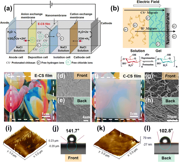
A four-compartment cell was used for continuous hydrogel deposition on a non-conductive surface, as shown in the schematic in Fig. 1a. The deposition cell and isolation cell were separated by a nanomembrane, which had a pore size of tens to 100 nm and allowed water molecules and ions to pass through but not chitosan molecules. The anode cell and the deposition cell were separated by an anion exchange membrane, which effectively prevented H+ produced by the anode from reaching the vicinity of the nanomembrane and thereby corroding the chitosan film. When H+ accumulated on the surface of the chitosan film, the local pH value decreased, which caused the protonation and dissolution of chitosan, resulting in damage to the surface structure of the film. The isolation cell and the cathode cell were separated by a cation exchange membrane. The OH− ions produced by the electrolysis of water in the cathode area were blocked and could not reach the deposition cell to participate in the deposition process of chitosan. When an electric field intensity of 2–10 V cm−1 was applied for 30 min, a chitosan hydrogel film with a thickness of 0.08–0.64 mm was deposited on the surface of the nanomembrane facing the deposition cell.A previous study on chitosan deposition on electrodes suggests that the in situ sol–gel transition of chitosan is caused by the electrophoresis of chitosan chains to the cathode under an electric field and the increased pH gradient near the electrodes.39 However, the formation of the chitosan hydrogel film on the non-conductive surface was not caused by OH− generated at the cathode because the cation exchange membrane blocked the penetration of most OH−. In order to follow the migration of OH− or H+ generated by the electrodes, a pH indicator was added to the phosphate buffer in the cathode and anode chambers. During the electrodeposition process, the pH value did not change significantly in the chambers as no color change was observed. The concentration of H+ in the chitosan solution was determined by acid–base titration. It was found that the free hydrogen ion content in the chitosan solution decreased after electrodeposition. During this process, the hydrogen ions pass through the nanomembrane under the influence of the electric field, and the –NH3+ ⇌ –NH2 + H+ reaction proceeds toward deprotonation, causing the chitosan molecules to gather and get deprotonated on the surface of the nanomembrane to form a film (Fig. 1b). The electric field served not only as the driving force for the migration of chitosan molecules but also as the accelerator of the “electric-field-driven deprotonation” of chitosan. Notably, the electric field was necessary, as the control experiment only resulted in a turbid precipitate when a dialysis bag filled with chitosan solution was immersed in water for 5 days.
After applying an electric field of intensity 6 V cm−1 for 30 min, a transparent and uniform chitosan hydrogel film was observed on the surface of the nanomembrane in the deposition cell. Notably, no hydrogel film was formed on the other side of the nanomembrane in the isolation cell since the chitosan chain cannot pass through the nanopores of the nanomembrane. The formed chitosan hydrogel film was mechanically strong and could be easily peeled off from the nanomembrane. As seen in Fig. 1c, it was highly transparent, and both surfaces demonstrated a compact microstructure (Fig. 1d and e). In comparison, the casting chitosan film prepared by traditional base treatment was opaque (Fig. 1f), and a porous microstructure could be observed on both sides (Fig. 1g and h). As shown in Fig. S1 (ESI†), the transmittance of E-CS was over 80%, while the transmittance of C-CS ranged from 0% to 40%. A more detailed morphological analysis was carried out by atomic force microscopy. The AFM images in Fig. 1k reveal that the surface roughness of the back side was 10 nm, while the surface height of the front side was around 40 nm (Fig. 1i). The low roughness on the back side was caused by close attachment to the flat and uniform nanomembrane. The front side was at the sol–gel transition interface, and the semi-rigid chitosan chains formed a molecular brush-like structure, resulting in a rougher morphology. This microstructure discrepancy led to a difference in hydrophilicity between the front and back surfaces (Fig. 1j and l). Fourier transform-infrared spectroscopy (FT-IR) and X-ray diffraction analyses indicated that both E-CS and C-CS films were physically cross-linked without affecting the chemical functional group of the chitosan molecules (Fig. S2, ESI†). The electrodeposition process reduced the water content of the resulting E-CS film to 86% compared to 94% of the C-CS film (Fig. S3a, ESI†). Compared with the alkaline neutralization effect, the electric field benefited the oriented arrangement of the chitosan molecular chains, resulting in the formation of dense structures and a decrease in the water content of the chitosan hydrogels. In addition, the swelling ratio gradually decreased with increasing electric field intensity, ranging between 150% and 250% (Fig. S3b, ESI†).
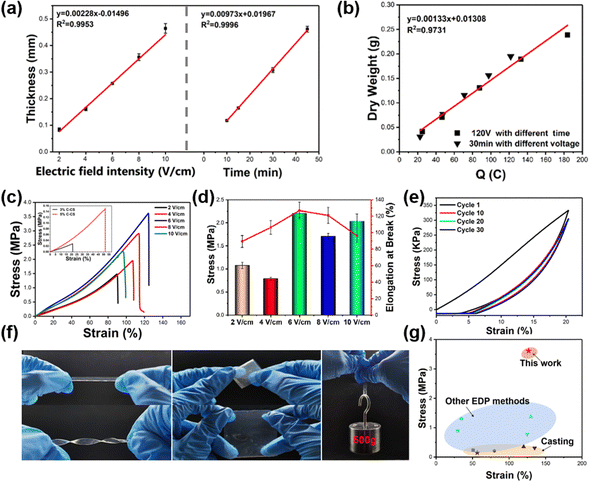
The growth kinetics of the E-CS film were monitored under various electric field intensities and times. Under the same deposition time, the thickness of the E-CS film increased with increasing electric field intensity. In addition, the thickness had a positive linear relationship with time in a certain electric field intensity range (Fig. 2a), indicating continuous growth of the chitosan hydrogel film. As shown in Fig. 2b, the amount of chitosan was directly proportional to the transferred charge, which is consistent with previous reports.40
The mechanical strength of the E-CS films increased from 1.47 MPa at 2 V cm−1 to 3.61 MPa at 6 V cm−1 and then dropped to 2.27 MPa at 10 V cm−1 (Fig. 2c). The low electric field strength may have led to a mismatch between chitosan deprotonation and aggregation, resulting in the formation of a continuous loose structure and reducing the mechanical properties of the film. The high electric field strength led to the rapid aggregation of chitosan and caused a deprotonation lag, resulting in a layered structure with voids between layers, which can also cause damage to the mechanical properties. In the conventional C-CS film, the high solid content improved the mechanical properties but even the film cast with 5 wt% chitosan exhibited a tensile strength of only about 1/20 of the E-CS films (inset in Fig. 2c). This was mainly because the chitosan molecules are tightly bound by hydrogen bonds due to the electric field effect during the electrodeposition process, and the water content is lower than that in the casting films, resulting in better mechanical properties. The fracture elongation and elastic modulus of the films also showed the same variation trend as tensile strength (Fig. 2d). Fig. 2e shows the cyclic tensile curves of the E-CS film under 20% strain for 30 cycles. The film overlapped well with the first tensile curve even after 30 stretching cycles, indicating its good elasticity and fatigue resistance. The E-CS film has sufficient flexibility and could recover its original shape after rotation, twisting, and folding. The E-CS film with a width of 5 mm could withstand a weight of 500 g (Fig. 2f). Fig. 2g compares the mechanical properties of the E-CS film with those reported in the literature, including films fabricated by casting, such as chitosan/lactic acid (0.23 MPa; 50.8%),41 chitosan/LiOH/KOH/urea/water solution (0.21 MPa; 80%),42 chitosan/β-glycerophosphate disodium salt/attapulgite (ATP) (0.35 MPa; 120%),43 chitosan/graphene oxide (0.31 MPa; 135%),44 and chitosan hydrogel films prepared by electrodeposition methods such as alternating current electrodeposition (0.89 MPa; 30%),45 electrodeposition/epichlorohydrin ECH (1.3 MPa; 34.74%),29 electrodeposition prepared tubular chitosan hydrogel (1.37 MPa; 130%),46 and chitosan/calcium ion/carbon nanotube tubular hydrogel (0.77 MPa; 125%).47 The mechanical properties of the E-CS film outperform the reported data. In addition, the chitosan hydrogel showed no cytotoxicity. When the extract of the hydrogel film was co-cultured with L929 cells for 24, 48, and 72 h, the cell viability was more than 100% (Fig. S4, ESI†), which shows its good biocompatibility. By sealing the nanomembrane with masks, E-CS films with different inner patterns could also be successfully prepared (Fig. S5, ESI†).
3.2 Structural regulation of the hydrogel film
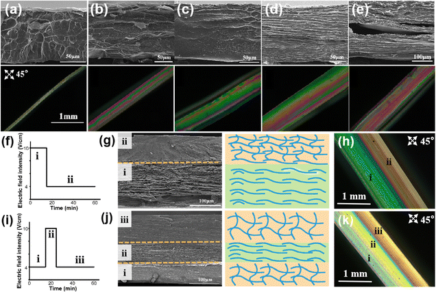
Next, we investigated whether the structure of the E-CS film could be easily regulated by applying different electric field intensities. The cross-section of the E-CS films prepared under different electric field intensities was observed by SEM and polarized optical microscopy (Fig. 3a–e). A continuous dense network with pore diameters of around 0.2–1 μm was observed at low electric field intensities. Encouragingly, a distinct ordered layered structure appeared at high electric field intensities. The polarized optical images indicated that with increasing electric field intensity, the interference color sequence gradually shifted from low-order to high-order color sequences, indicating the directional arrangement of chitosan molecules under an electric field.Since the microstructure of the chitosan hydrogel film could be directly influenced by electric field intensity, a predetermined electric field intensity sequence was designed to create a complex structural hydrogel film inspired by the hierarchical structure of natural tissues. As shown in Fig. 3f and g, a bilayer hydrogel with a microstructural change from ordered to disordered arrangement was continuously constructed by applying an electrical signal sequence of 10 and 4 V cm−1. Notably, the ordered and disordered layers were seamlessly linked through continuous electro-growth, which is difficult to achieve by conventional methods. The polarized light image confirmed that the hydrogel contained two layers with different orientations (Fig. 3h). When the electric field intensity was changed from 4 to 10 V cm−1 and then back to 4 V cm−1 (Fig. 3i), a tri-layer hydrogel with a corresponding disordered–ordered–disordered arrangement was obtained (Fig. 3j and k), suggesting the successful formation of chitosan hydrogel films with hierarchical structures based on the arrangement of molecules from a microscopic to macroscopic level.
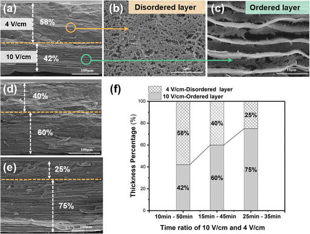
The cross-sectional SEM image in Fig. 4a reveals that the disordered layer has a porous structure (Fig. 4b), whereas the ordered layer has a well-aligned layered structure (Fig. 4c). Benefiting from the continuous electro-growth dominated by time, in the bilayer hydrogel, the thickness ratio of the ordered layer to disordered layer could be controlled by varying the deposition time under different electric field intensities (4 V cm−1 and 10 V cm−1) (Fig. 4d and e). During a total deposition time of 60 min, when the deposition time at an applied electric field intensity of 10 V cm−1 was increased from 10 min to 25 min, the thickness ratio of the ordered layer increased from 42% to 75%. Conversely, as the deposition time at the electric field intensity of 4 V cm−1 was decreased, the thickness ratio of the disordered layer decreased from 58% to 25% (Fig. 4f).
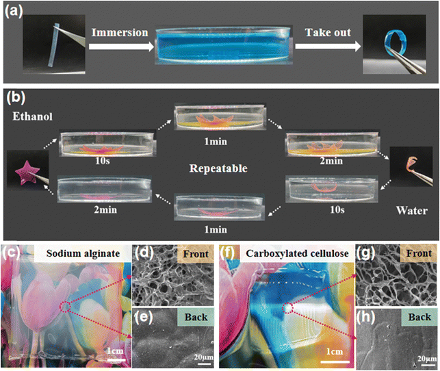
Due to the different structures and elastic moduli of the disordered and ordered layers, the bilayer hydrogel film could undergo directional deformation under specific conditions. Fig. 5a shows that when a hydrogel strip with the bilayer structure was immersed in a Cu2+ solution, the copper ions chelated with the amino groups of the chitosan molecules, causing the hydrogel to shrink. The disordered layer has a porous structure and a significant shrinkage in Cu2+, thus the hydrogel strip bent from the ordered layer to the disordered layer to form a circle. At the same time, the prepared bilayer hydrogel could also quickly undergo complete directional deformation and recovery in ethanol and water solutions, resulting in the interconversion of the hydrogel film from a 2D plane to a 3D flower shape (Fig. 5b). Finally, the generality of the electro-assembly method was evaluated with two other negatively charged polymers (sodium alginate and carboxylated cellulose). After applying an electric field intensity of 6 V cm−1 for 30 min, thick and transparent hydrogels were formed on the nanomembrane side close to the cathode (Fig. 5c and f). The formed hydrogels were peeled off from the nanomembrane, and the microstructures of the front and back sides were observed. The SEM images showed that both hydrogels have a loose porous structure (a few microns to tens of microns) on the front (Fig. 5d and g) while a smooth and dense structure was observed on the back sides (Fig. 5e and h), suggesting the heterogeneous structure of the electro-assembled hydrogel films. These results indicate that the continuous electro-assembly method on non-conductive surfaces has wide application in the controlled preparation of charged polymer hydrogels.
4. Conclusions
In summary, a new electro-assembly method for preparing polymeric hydrogel films on non-conductive surfaces is reported in this study. Compared with traditional electrodeposition methods, this approach effectively avoids the harsh electrolysis reactions at the electrode surface that can impact the hydrogel formation process. The resulting hydrogel films were structurally dense, mechanically strong, and have controllable thickness, structure, and geometry. To simulate the hierarchically ordered structure of biological soft tissues, we used programmable electrical signals and achieved the continuous electro-growth of chitosan hydrogels with regulated ordered and disordered structures. The findings of this work will provide a solid foundation for fabricating complex hydrogel materials to achieve various biological functions. Additionally, this method is applicable to other charged biopolymers. Therefore, our work provides an effective method for the preparation of biopolymer hydrogels and offers a new design concept for the development of hydrogel-based materials and devices.Author contributions
Yuncheng Xu: investigation, methodology, and writing – original draft, review, and editing. Jun Tong: investigation, methodology, and data curation. Jingxian Zhang: data curation, and writing original draft. Yuting Li: data curation. Xiaowen Shi: conceptualization, supervision, project administration, writing – original draft, review, and editing, fund acquisition. Hongbing Deng: conceptualization, writing – review and editing, and data curation. Yumin Du: conceptualization, and writing – review and editing.Conflicts of interest
The authors declare no conflict of interest.Acknowledgements
This work was supported by the National Natural Science Foundation of China (22075215; 22275141).References
- H. Abe and R. Funada, IAWA J., 2005, 26, 161–174 Search PubMed.
- P. Fratzl and R. Weinkamer, Prog. Mater. Sci., 2007, 52, 1263–1334 CrossRef CAS.
- M. A. Meyers, P.-Y. Chen, A. Y.-M. Lin and Y. Seki, Prog. Mater. Sci., 2008, 53, 1–206 CrossRef CAS.
- A. Hasan, A. Paul, A. Memic and A. Khademhosseini, Biomed. Microdevices, 2015, 17, 88 CrossRef PubMed.
- A. J. Sophia Fox, A. Bedi and S. A. Rodeo, Sports Health, 2009, 1, 461–468 CrossRef PubMed.
- N. Wang, Y. Peng, W. Zheng, L. Tang, S. Cheng, J. Yang, S. Liu, W. Zhang and X. Jiang, Macromol. Biosci., 2018, 18, 1700408 CrossRef PubMed.
- X. Le, W. Lu, J. Zhang and T. Chen, Adv. Sci., 2019, 6, 1801584 CrossRef PubMed.
- H. Tan, X. Yu, Y. Tu and L. Zhang, J. Phys. Chem. Lett., 2019, 10, 5542–5551 CrossRef CAS PubMed.
- X. Qiu, S. Liang, X. Huang and L. Zhang, Chem. Commun., 2019, 55, 15049 RSC.
- M. H. Ayoubi-Joshaghani, K. Seidi, M. Azizi, M. Jaymand, T. Javaheri, R. Jahanban-Esfahlan and M. R. Hamblin, Adv. Funct. Mater., 2020, 30, 2004098 CrossRef CAS.
- P. Bertsch, M. Diba, D. J. Mooney and S. C. G. Leeuwenburgh, Chem. Rev., 2022, 123, 834–873 CrossRef PubMed.
- M. Niazi, E. Alizadeh, A. Zarebkohan, K. Seidi, M. H. Ayoubi-Joshaghani, M. Azizi, H. Dadashi, H. Mahmudi, T. Javaheri, M. Jaymand, M. R. Hamblin, R. Jahanban-Esfahlan and Z. Amoozgar, Adv. Funct. Mater., 2021, 31, 2104123 CrossRef CAS.
- L. Hu, P. L. Chee, S. Sugiarto, Y. Yu, C. Shi, R. Yan, Z. Yao, X. Shi, J. Zhi, D. Kai, H. D. Yu and W. Huang, Adv. Mater., 2023, 35, 2205326 CrossRef CAS PubMed.
- M. Shin, J. Lim, J. An, J. Yoon and J.-W. Choi, Nano Convergence, 2023, 10, 8 CrossRef CAS PubMed.
- J. Duan, R. Hou, X. Xiong, Y. Wang, Y. Wang, J. Fu and Z. Yu, J. Mater. Chem. B, 2013, 1, 485–492 RSC.
- C. Vigier-Carrière, F. Boulmedais, P. Schaaf and L. Jierry, Angew. Chem., Int. Ed., 2018, 57, 1448–1456 CrossRef PubMed.
- Y. Chen, S. Li, X. Li, C. Mei, J. Zheng, S. E, G. Duan, K. Liu and S. Jiang, ACS Nano, 2021, 15, 20666–20677 CrossRef CAS PubMed.
- Q. Cheng and L. Jiang, Angew. Chem., Int. Ed., 2016, 56, 934–935 CrossRef PubMed.
- M. Hua, S. Wu, Y. Ma, Y. Zhao, Z. Chen, I. Frenkel, J. Strzalka, H. Zhou, X. Zhu and X. He, Nature, 2021, 590, 594–599 CrossRef CAS PubMed.
- M.-A. Shahbazi, M. Ghalkhani and H. Maleki, Adv. Eng. Mater., 2020, 22, 2000033 CrossRef CAS.
- S. Choi and J. Kim, J. Mater. Chem. B, 2015, 3, 1479–1483 RSC.
- M. Tang and C. Ke, Matter, 2021, 4, 2664–2665 CrossRef CAS.
- K. Uetani, T. Okada and H. T. Oyama, ACS Macro Lett., 2017, 6, 345–349 CrossRef CAS PubMed.
- Y. Huang, X. Li, A. J. Poudel, W. Zhang and L. Xiao, Appl. Mater. Today, 2022, 29, 101668 CrossRef.
- K. Uetani, H. Koga and M. Nogi, Nanomaterials, 2020, 10, 958 CrossRef CAS PubMed.
- G. Yang, H. Lin, B. B. Rothrauff, S. Yu and R. S. Tuan, Acta Biomater., 2016, 35, 68–76 CrossRef CAS PubMed.
- E. Avcu, F. E. Baştan, H. Z. Abdullah, M. A. U. Rehman, Y. Y. Avcu and A. R. Boccaccini, Prog. Mater. Sci., 2019, 103, 69–108 CrossRef CAS.
- M. A. Brites Helú and L. Liu, Chem. Eng. J., 2021, 416, 129029 CrossRef.
- C. Yang, M. Wang, W. Wang, H. Liu, H. Deng, Y. Du and X. Shi, Carbohydr. Polym., 2022, 292, 119678 CrossRef CAS PubMed.
- J. Li, S. Wu, E. Kim, K. Yan, H. Liu, C. Liu, H. Dong, X. Qu, X. Shi, J. Shen, W. E. Bentley and G. F. Payne, Biofabrication, 2019, 11, 032002 CrossRef CAS PubMed.
- J. Tong, C. Yang, L. Qi, J. Zhang, H. Deng, Y. Du and X. Shi, Chem. Commun., 2022, 58, 5781–5784 RSC.
- M. T. I. Mredha, H. H. Le, J. Cui and I. Jeon, Adv. Sci., 2020, 7, 1903145 CrossRef CAS PubMed.
- X. Guo, H. Gao, J. Zhang, L. Zhang, X. Shi and Y. Du, Carbohydr. Polym., 2021, 254, 117464 CrossRef CAS PubMed.
- M. Cheong and I. Zhitomirsky, Colloids Surf., A, 2008, 328, 73–78 CrossRef CAS.
- N. Taira, K. Ino, J. Robert and H. Shiku, Electrochim. Acta, 2018, 281, 429–436 CrossRef CAS.
- B. P. Carr, Z. Chen, J. H. Y. Chung and G. G. Wallace, Polymers, 2022, 14, 4027 CrossRef PubMed.
- M. Lei, X. Qu, H. Wan, D. Jin, S. Wang, Z. Zhao, M. Yin, G. F. Payne and C. Liu, Sci. Adv., 2022, 8, eabl7506 CrossRef PubMed.
- M. Lei, S. Zhang, H. Zhou, H. Wan, Y. Lu, S. Lin, J. Sun, X. Qu and C. Liu, ACS Nano, 2022, 16, 10632–10646 CrossRef CAS PubMed.
- B. H. Huang, L. J. Chen, Y. J. Chiou, G. Whang, Y. Luo, Y. Yan, K. H. Wei, X. He, B. Dunn and P. W. Wu, Adv. Sci., 2022, 9, 2203948 CrossRef CAS PubMed.
- K. Yan, F. Ding, W. E. Bentley, H. Deng, Y. Du, G. F. Payne and X.-W. Shi, Soft Matter, 2014, 10, 465–469 RSC.
- S. Sayyar, E. Murray, B. C. Thompson, J. Chung, D. L. Officer, S. Gambhir, G. M. Spinks and G. G. Wallace, J. Mater. Chem. B, 2015, 3, 481–490 RSC.
- J. Duan, X. Liang, Y. Cao, S. Wang and L. Zhang, Macromolecules, 2015, 48, 2706–2714 CrossRef CAS.
- Q. Wang and D. Chen, Carbohydr. Polym., 2016, 136, 1228–1237 CrossRef CAS PubMed.
- Y. Wang, S. Liu and W. Yu, Macromol. Biosci., 2021, 21, 2000432 CrossRef CAS PubMed.
- B.-H. Huang, S.-Y. Li, T.-T. Chiang and P.-W. Wu, Carbohydr. Polym., 2020, 250, 116912 CrossRef CAS PubMed.
- K. Nawrotek, M. Tylman, K. Rudnicka, J. Gatkowska and M. Wieczorek, Carbohydr. Polym., 2016, 152, 119–128 CrossRef CAS PubMed.
- K. Nawrotek, M. Tylman, K. Rudnicka, J. Gatkowska and J. Balcerzak, J. Mech. Behav. Biomed. Mater., 2016, 60, 256–266 CrossRef CAS PubMed.
Footnotes |
| † Electronic supplementary information (ESI) available. See DOI: https://doi.org/10.1039/d3ma01139a |
| ‡ Yuncheng Xu and Jun Tong contributed equally to this work. |
| This journal is © The Royal Society of Chemistry 2024 |

