 Open Access Article
Overview of CO2 capture and electrolysis technology in molten salts: operational parameters and their effects
Qiuji
Zhu
a,
Yimin
Zeng
*b and
Ying
Zheng
 *a
*a
aDepartment of Chemical and Biochemical Engineering, Western University, London, Ontario, Canada. E-mail: Ying.zheng@uwo.ca
bNatural Resources Canada–CanmetMaterials, Hamilton, Ontario, Canada. E-mail: yimin.zeng@NRCan-RNCan.gc.ca
First published on 6th June 2023
Abstract
Carbon capture and storage (CCS) technology is believed to be a promising solution for global CO2 emission control and climate change. However, the application of CCS projects is facing a dilemma due to their negative cash flow. To address the challenge, it is critical to adopt an innovative technology that can capture and convert CO2 simultaneously with satisfying efficiencies and can make a profit for the end users. Recently, molten salt CO2 electrolysis that splits CO2 into carbon and oxygen has been extensively studied. This study reviews the process mechanisms, the salt selection, and the effects of operating conditions, including temperature and voltage. In most reported articles, the CO2 to carbon conversion efficiency reached at least 80%, and the current efficiency is over 90%, proving the promising potential of the molten salt CO2 electrolysis method. Still, some aspects, such as the impurities' influences and electrode corrosion, have not been thoroughly investigated. Therefore, some suggestions are recommended for future work.
Keywords: CO2 capture; CO2 conversion; Molten salt CO2 electrolysis; CO2 reduction; Carbon nanotubes.
1 Introduction
1.1 CO2 emission
The first recognition of the negative impact of CO2 can be traced back to the 1870s when European scientists concluded that carbonic acid, a by-product of rapidly expanded industrialization, contributed to acid rain and artificial warming.1 Later in 1936, lime scrubbing was first introduced to treat fuel gas, but this step was mainly targeted at the reduction of sulphur oxides.2 The research focusing on CO2 capture and separation was primarily initiated and driven by commercial interests, such as urea yield boosting, carbonated drinks, and most importantly enhanced oil recovery (EOR).3,4 The CO2 was sold at 50 USD per ton CO2 for the EOR project, which essentially encouraged CO2 capture.5 There were over 140 EOR projects recorded in 2013, 88% of which were built in the USA.3,4It is undeniable that carbon dioxide capture commercial programs are tied closely to both global and national political considerations and further, complicated by technological developments. The debates between the industry sectors and governments have been taking place for decades.6,7 Since the 1970s, it has been witnessed that conferences and organizations increasingly promoted awareness of the harmful effects of CO2 on all humankind and made countries collaborate to set up policies and projects.8 Interestingly, the 1970s was also the year when the first CO2 capture project applied for EOR, showing timeline overlaps between concepts and application developments.3 The necessity of decarbonization and sustainability finally received special attention from policymakers and the public.
Carbon emissions are highly related to human activities. Thus, sorting out emission sources is the first step to adopting carbon capture projects. The pie chart in Fig. 1 provides a comprehensive breakdown of sectors contributing to global emissions. Energy-related sectors take the largest portion, 73.2%, where most energy used in this sector is supported by fuel combustion.9 The trend of energy-related CO2 emissions by fuel has kept increasing in the past 21 years, as shown in Fig. 2. In 2021, the greenhouse gas emission rose to another new peak, reaching a total of 40 Gt (gigatons) CO2.10 As coal-fired plants owned the cheapest operation cost, these plants guaranteed that coal was the leading fuel for energy generation and the top and stable CO2 emission source. Oil and natural gas-related emission sources rebounded to 18.2 Gt, while coal emission sources reached a new-time peak of 15.3 Gt in 2021. The post-combustion is the most conventional and typical process in current thermal power plants. Although the CO2 outlet level has a relatively lower concentration, only around 13 to 15%, post-combustion stands as a more competitive option because of finial considerations regarding technological barriers and costs.11 Therefore, post-combustion CO2 capture from power plants, especially coal-fired plants, has attracted substantial research interest. However, it is noticed that the Canadian Boundary Dam is, up to date, the only carbon capture and sequestration (CCS) project capturing post-combustion CO2 from power generation.12 The gap between the CCS project and research interests not only results from unmatured technologies but is also affected by the massive costs and investments.
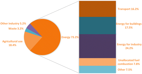 | ||
| Fig. 1 Global greenhouse gas emissions by different industrial sectors with data collected from open-access ref. 9 with permission from Our World in Data, copyright 2020. | ||
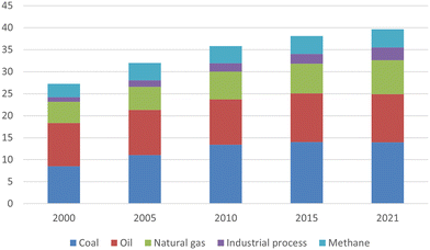 | ||
| Fig. 2 Global energy-related CO2 emissions by fuel types reproduced from open-access ref. 10 with permission from International Energy Agency, copyright 2022. | ||
Many countries throughout the world actively initiate applicable policies for CO2 reduction and heavily invest in research programs as well as major industrial-scaled CO2 capture initiatives. Norway, for example, is the first country that implemented the carbon tax and operated the first large-scale Sleipner CCS project, applying monoethanolamide (MEA) absorption to purify natural gas containing 9% CO2.3,13 Norway went through severe debates with the energy-intensive industry, revealing the complex impacts of the negotiated political economy on the project implementation.7 The Norwegian Sleipner project inspired the birth of many other projects, such as Salah CO2 Storage in Algeria in 2004 and the Snøhvit CO2 Storage Project in Norway in 2008.3 In 2014, Canada initiated the first industrial-scaled Boundary Dam CCS project in Saskatchewan to separate CO2 from flue gases using amine absorption.3,13 A fraction of the captured CO2 was sold and applied to EOR, and the rest was stored via the Aquistore project in Saskatchewan.14 The most recent CCS project, named Alberta Carbon Trunk Line, was built in Alberta, Canada, in 2020. MEA and methanol are used as absorbents to capture CO2 from Sturgeon Refinery and Nutrient Redwater fertilizer plant.15 According to Global CCS data, Canada has four commercial CCS projects, considering its high carbon tax of $50 per tonne of carbon dioxide equivalent emissions.16
1.2 CO2 capture & conversion methods
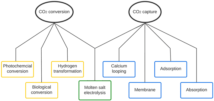
Several CO2 capture methods have been proposed and validated in the past decades. Fig. 3 shows the typical classification of the carbon capture methods, including chemical absorption, adsorption, membrane separation, and calcium looping. Molten salt electrolysis, as an advanced method, can capture post-combustion flue gas and convert it into more valuable products to offset costs.Amine absorption is the most mature and well-studied chemical absorption method for CO2 capture.17 Its application can be traced back to the 1930s.2 Most industrial-scaled CO2 capture plants, including the two post-combustion CO2 capture plants operated at Boundary Dam and Petra Nova in Canada, employ the amine absorption method.11,18,19 However, solvent regeneration requests elevated temperatures, which causes a vast energy penalty. In addition to energy consumption, the corrosivity and high volatility of amine solvents can cause various operational issues.20–23 Adsorption is another method that has been successfully applied in industrial-scale CO2 capture plants, such as Air Products facilities for hydrogen production.3,18 Natural sorbents, such as natural zeolites, natural plants (such as fruit shells), and coal-based materials, can be selected to perform adsorption, or human-made sorbents, such as activated carbon, metal–organic frameworks (MOFs), and zeolite, can adsorb CO2.24–26 So far, this pathway faces more challenges than absorption as the overall performance is even worse: high material costs (especially for MOFs), capacity loss during the process, high regeneration cost, and low adsorption capability (3–11 wt%), etc.21 Other promising methods include membrane separation, calcium looping, and cryogenic separation.25
The above-mentioned conventional methods produce purified CO2 and thus raise the same problem, which is the cost. The amount of purified CO2 used for EOR and other industries is limited, and a large portion of captured CO2 has to be stored, which leads to a negative cash flow. It explains the fact that there are only a few CCS projects, practically of which are funded by governments. Taking the Canadian Quest plant as an example, it requires average funding of 30 million annually for operation.15 The Petra Nova project is another example, which captured the power plant's post-combustion CO2 using amine absorption and sold for EOR. However, it was abruptly closed its business after only three years of operation due to imbalanced costs.22 Due to its profit-driven nature, private corporations or even governments would only start to or continue operating CCS projects if they can generate profits and cover the cost of the carbon tax and other possible budgets.
Numerous carbon conversion methods have been reported and well-studied.23,27–30 A variety of conversion methods, such as photochemical, biological, and hydrogen transformation pathways, are being developed for industrial applications.31–34 The advantage of these methods is that they can obtain hydrocarbons and other marketable products (such as dimethyl carbonate, synthesis gas, carboxylic acids, methane, etc.) that are significantly more valuable than pure CO2. However, the deployment of these methods still faces critical challenges, such as evaporation occurring under high-temperature gas inlets, difficulty in final product separation, requirement on high CO2 concentration feedstock. Moreover, some of the proposed methods likely suffer the unsatisfying production rates and the limitation of equilibrium and CO2 solubility. For instance, the conversion of CO2 to dimethyl carbonate was only around 1–5% due to the chemical equilibrium limitation.23 It was also reported that the production using alkaline electrolytes, such as KOH, is restricted to the conversion of CO2 to CO less than 50% due to the formation of carbonates and bicarbonates.27
Molten salt CO2 electrolysis is a novel technology combining CO2 capture and conversion. The development of the method was initiated in the 1960s and has quickly expanded since the 2000s. This method allows to capture CO2 from hot flue gas, and the captured CO2 can be directly converted in the molten salt electrolyte at high temperatures into valuable products, such as carbon, carbon monoxide, and O2.35 As CO production requires more energy consumption and presents lower current efficiency, CO would not be an ideal product. Researchers show more interest in producing high-quality carbon materials and manipulating their nanostructures.
As its electrolyte contains zero water and targets carbon formation, molten salt electrolysis can result in a single solid carbon product with high current efficiency and avoid complex products with tough or multiple separations. Additionally, the in situ conversion of CO2 to value-added products prevents extra costs after carbon capturing, such as CO2 transportation costs, debatable and uncertain storing, maintenance costs, etc.18,36 A molten salt CO2 electrolysis plant is estimated to bring a net profit of $50![[thin space (1/6-em)]](https://www.rsc.org/images/entities/char_2009.gif) 000 per ton of captured CO2 for a power plant when the final electrolysis product is carbon nanotubes (CNTs).37 One common approach for growing CNTs is chemical vapour deposition (CVD), which anticipates requiring at least 1440 MJ and emitting 28.55 kg CO2e for producing one gram of CNTs,38,39 Therefore, this profit and benefits can drive the molten method to potential scale-up plants and promote the carbon capture installed in general power plants, overweighing the financial burdens that the above-mentioned conventional methods have. This report will focus on this electrolysis method for carbon capture and conversion.
000 per ton of captured CO2 for a power plant when the final electrolysis product is carbon nanotubes (CNTs).37 One common approach for growing CNTs is chemical vapour deposition (CVD), which anticipates requiring at least 1440 MJ and emitting 28.55 kg CO2e for producing one gram of CNTs,38,39 Therefore, this profit and benefits can drive the molten method to potential scale-up plants and promote the carbon capture installed in general power plants, overweighing the financial burdens that the above-mentioned conventional methods have. This report will focus on this electrolysis method for carbon capture and conversion.
2 Molten salt CO2 electrolysis system
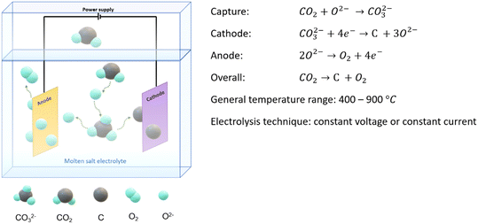
Molten salt CO2 electrolysis is used to capture CO2 and electrochemically convert the captured CO2 into valuable products, including solid carbon, oxygen, and carbon monoxide. The key components of the system contain electrolytes, electrodes, and an external power supply, as shown in Fig. 4. Electrolytes are melted salts containing zero water at a temperature higher or equal to melting points, and they are responsible for capturing inlet CO2 and transferring ions and electrons. Product evolution and deposition occur on the electrode surfaces. In general, the inlet CO2 is electrochemically split into oxygen and carbon or oxygen and carbon monoxide under harsher high-temperature conditions.CO2 is firstly absorbed by O2− or CO32− ions and turned into carbonate or dicarbonate ions. Then, CO32− ions primarily follow a single-step reduction on the cathode through a 4-electron transfer, resulting in carbon deposition on the cathode and releasing oxygen ions. However, at higher temperatures, CO32− ions tend to undergo a 2-electron transfer instead of a 4-electron to form CO as the final product on the cathode due to the fact that the generation of CO is more thermodynamically favourable than the formation of carbon. Note that the movement of carbonate ion is against the electric field since the reduction reaction exclusively happens on the cathode, and the driving force of concentration gradient overweighs the repulsion force of the electric field. The decreased carbonate ions at a cathode zone were reported in LSV tests, and the reduction of carbonate ions was found to weaken the electric current during constant voltage electrolysis. However, the effects of the electric field have never been reported nor compared to the concentration driving force. This topic should be investigated in the future to understand the cathodic electrolysis mechanism in a continuous operation.
The produced oxygen ions can either remain in the system to enhance CO2 absorption or be oxidized as oxygen gas and then released from the anode. The whole electrolysis takes place in molten salt, which involves zero water. This can significantly avoid the competitive water split reaction. Thus, the current efficiency is improved and remains over 80%. Also, the formation of a complex hydrocarbon mixture is also avoided, so the product separation is much easier. As a result, the conversion of CO2 to carbon and oxygen is more competitive as the current efficiency can exceed 90%.40,41 However, when CO and oxygen are the desirable products, the process cannot achieve 90% carbon conversion at equal conditions. Thicker CO2 inlet concentration (over 14%) and more extreme temperatures (at 900 °C) were required to push CO production to 90% conversion.42 Additionally, the current efficiency for CO manufacturing purposes was relatively low, only around 36.9%, and this can be explained by unwanted side reactions.42 More detailed mechanisms and reactions are discussed in the later section.
Table 1 lists the molten salt CO2 electrolysis reported since 2019, and the records before 2019 can be found in Jiang's review.62 Additionally, the generated records focus on the cases utilizing carbonate electrolytes, and the reasons will be discussed in detail in the electrolyte section. The trend between 2019 and 2022 can be classified into 3 major types: 1. Production of specific carbon nanostructure by modifying operation conditions and electrolysis system components;43,44 2. Method and equipment improvements, including separation improvement and reactor design;45,46 3. Expansion of molten salt CO2 electrolysis to produce other materials, such as hydrocarbons.47,48
| Electrolyte | T (°C) | Cathode | Anode | Current/current density | Carbon related products | Ref. |
|---|---|---|---|---|---|---|
| Note: this table includes reported molten salt electrolysis since 2019 and focuses on carbonate electrolytes. Reports prior to 2019 can be found in Jiang's review.62 | ||||||
| Li2CO3 | 770 | Galvanized steel; Ni–Cr | Ni–Cr; galvanized steel | 1 A | Multi-walled carbon nanotubes (MWCNTs) | 49 |
| Ta2O5–CaCl2–CaO | 650 | Ni | Graphite | 0.2–1 A cm−2 | Carbon particles | 50 |
| Li2CO3–Li2O | 770 | Cu | Ir–Pt | 0.2 A cm−2 | Carbon nano-onions; CNTs | 51 |
| Li2CO3–Li2O–CaO–H3BO3 | 770 | Muntz brass sheet | Nichrome sheet | 0.2 A cm−2 | Carbon nanotubes (CNTs) | 52 |
| Li2CO3–Na2CO3–K2CO3–H3BO3 | 670 | Muntz brass sheet | Inconel | CNTs | 53 | |
| Li2CO3–Na2CO3–K2CO3 | 450–650 | Ni | SnO2 | 0.2–4 A g−1 | Activated carbons | 54 |
| KCl–LiCl; LiOH–NaOH; KOH–NaOH; Li2CO3–Na2CO3–K2CO3 | 225–475 | Ti | Graphite | CO; hydrocarbons, H2 | 47 | |
| Li2CO3–Li2O | 770 | Muntz brass as | Inconel 718; Nichrome; Incoloy | 0.5 A | Fe3C; CNTs | 55 |
| LiCl–Li2CO3–LiBO2 | 550 | Ni | Graphite | 25–100 mA cm−2 | CO | 56 |
| LiCl–Li2CO3–LiBO2 | 550 | Ni | Graphite | Carbon nanofibers (CNFs); CO | 57 | |
| Li2CO3 | 730 | Galvanized steel | Pt | Graphene; CNTs | 43 | |
| Li2CO3–K2CO3–Na2CO3 | 650 | NiO–Co3O4 | Ni10Cu11Fe | 10 mA cm−2 | NiCo@g-c powder | 58 |
| Li2CO3–K2CO3–Na2CO3 | 650–750 | Ni | Pt | 5–100 mA cm−2 | Graphite | 59 |
| MCO3–Na2CO3–K2CO3 (M = Mg, Ca, Sr, and Ba) | 710–850 | Ni | Ni10Cu11Fe | 3 V | Carbon particles | 60 |
| Li2CO3–K2CO3–Na2CO3 | 450 | Ni | Pt–Ti | 100 mA cm−2 | Electrolytic carbon | 61 |
| Li2CO3–Na2CO3 | 750 | Brass | Inconel 718 | 200 mA cm−2 | CNTs | 45 |
| Li2CO3–Fe2O3; Li2CO3–Fe2O3–Ni | 770 | Muntz brass; Monel | Inconel 718; Nichrome; Inconel 600; Ni; Ir | 8–600 mA cm−2 | CNTs | 44 |
| Li2CO3 | 750 | Ni | SS | 7.5 A | Carbon sphere | 46 |
| Li2CO3; Li2CO3–Na2CO3–K2CO3–LiOH; Li2CO3–CaCO3–BaCO3 | 450–750 | Fe | Ni | 10–450 mA cm−2 | CNTs; CO; H2; CH4 | 48 |
2.1 Electrochemical conversion mechanism
In a molten salt system, the reactions on the surface of electrodes are monitored closely via cyclic voltammetry (CV) measurements. At sufficiently high temperatures (a temperature higher than the melting points of selected salts), the desired electrochemical reactions for the carbon formation are shown below:35,63| Cathode: CO32− + 4e− ↔ C + 3O2− | (1) |
| Anode: 2O2− ↔ O2 + 4e− | (2) |
| CO2 + O2− ↔ CO32− | (3) |
| CO32− + CO2 → C2O52− | (4) |
| CO32− + 2e− ↔ CO + 2O2− | (5) |
| M+ + e− ↔ M (M = Li, Na, Ca or K) | (6) |
| MnCO3 ↔ CO2 + MnO | (7) |
| MnO (liquid) = MN+ + O2− (M = Li, Na, Ca or K) | (8) |
| nM + CO2 = CO + MnO (M = Li, Na, Ca or K) | (9) |
| 2CO ↔ CO2 + C | (10) |
| C + nO2− ↔ COn + 2ne− (n = 1 or 2) | (11) |
| C + 2CO32− ↔ 3CO2 + 4e− | (12) |
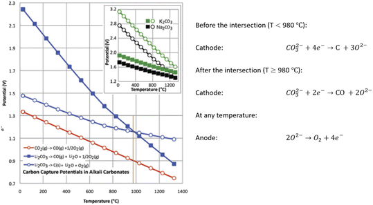 | ||
| Fig. 5 Electrochemical conversion potential for carbon capture and conversion centra Li2CO3 (main figure), or Na2CO3 or K2CO3 (figure inset); in the inset, squares refer to M2CO3 → C + M2O + O2 and circles to M2CO3 → CO + M2O + ½ O2. To the right of the brown vertical line, CO is preferred. And C is preferred to the left of the line.74 | ||
Molten salt CO2 capture and electrochemical transformation is a complex system. Thus, there is a list of parameters or components affecting the performance, products, energy consumption, etc. The parameters include cell components (electrolytes and electrodes), feeding stream, and operation conditions (power supply and temperature). In most cases, the carbon products are amorphous. A small number of impurities may also be identified depending on different operation conditions.35,70,73 Therefore, carbons of different morphologies can be obtained by adjusting the operating conditions.
2.2 Electrolytes
In addition to molten salts, electrolytes can be replaced by aqueous solutions, ionic liquids, and solid electrolytes. Different electrolytes exhibit various selectivity, products, and efficiency. Electrolytes are crucial for collecting CO2 from the incoming gas stream and transferring ions. Aqueous solutions are impractical when served as electrolytes due to a number of significant disadvantages, including poor electrochemical windows, water splitting, limited solubility, and slow reaction kinetics.35,75 Ionic liquids show excellent chemical stability, high CO2 solubility, and high conversion yield, but the high cost and low reaction kinetics hinder them from commercial-scaled applications.35,76 Solid electrolytes have an overall higher current efficiency, but their specific conductivity is less than half that of molten salt electrolytes.62 Even worse, sulphur impurities negatively affect the solid electrolytes, making this type of electrolytes unfavoured for capturing power plant flue gas commonly containing sulphur compounds.62Many researchers believe high-temperature molten salts are the optimal electrolyte because of their satisfying properties. Molten salts present low toxicity, high heat capacity, wide electrochemical operating window, high ionic conductivity, and low costs due to abundant availability.77 Furthermore, the same metal oxide components, for example, Li2O, show an enhanced CO2 absorption ability in the molten phase compared to the solid phase.78 Impurities from flue gas, SO2 and NO2, can be converted into valuable S/N-doped carbon materials.78,79 Selecting a molten salt electrolyte is considered more crucial than choosing an electrode since electrolytes have a greater impact on the final carbon product. Wang observed that carbonates and oxides impacted the nanostructures of resulted carbon, while five different cathodes produced little changes to the final product.80
Carbonates, chlorides, and oxides containing Li+, Ca2+, Na2+, and K+ are the most widely researched electrolytes due to their wide electrochemical windows and good CO2 solubility.62 Carbonates and chlorides take up a large portion of salts, and oxides are commonly used as additives, ranging from 1 wt% to 30 wt%. The types of salts present distinct advantages and drawbacks, and as a result, they are commonly mixed together to achieve optimal performance, such as lower melting points. But before mixing, it is essential to identify the features of salts first.
| Salt system | Melting point (°C) |
|---|---|
| Li2CO3 | 723 |
| Na2CO3 | 854 |
| K2CO3 | 891 |
| Li2CO3–Na2CO3 (52–48 mol%) | 501 |
| Li2CO3–K2CO3 (62–38 mol%) | 498 |
| Na2CO3–K2CO3 (56–44 mol%) | 710 |
| Li2CO3–Na2CO3–K2CO3 (43.5–31.5–25 mol%) | 397 |
| K2CO3–MgCO3 (57–43 mol%) | 460 |
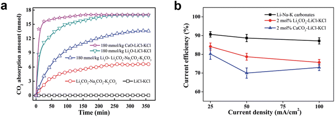 | ||
| Fig. 6 (a) CO2 absorption curves in different molten salts at 450 °C with the CO2 partial pressure of 50 kPa; (b) current efficiency for galvanostatic electrolysis in different molten salts under CO2 atmosphere at 450 °C.76 | ||
Another difference between carbonates and chlorides is the solubility of additives, such as CaO and Li2O, which later lead to different reaction mechanisms. CaO or Li2O is soluble in CaCl2 but hardly dissolves in carbonates.78,81,84 Chloride electrolytes typically contain oxide additives. However, they still have overall fewer oxygen ions than carbonate electrolytes, which can reduce the adverse effects of the consumption of deposited carbon as indicated in eqn (11) and (12).41 However, when CO32− is wholly consumed in chlorides, the current density reaches nearly zero.81 It indicates neither pure chlorides are suitable for CO2 splitting, nor chlorides with additives are stable for long-term electrolysis. A more detailed and comprehensive review focusing on chloride salts can be found in Díez's report, including how the salts and added biomass serve as templates for the formation of micro-pores, which resulted in various carbon nanostructures.85
For carbonate electrolytes, the solubility of its oxide or additives leads to two different mechanisms. For insoluble oxides (such as CaO), the primary electrolysis reaction refers to the conversion of carbonates (CaCO3) into corresponding oxides (CaO) and carbon deposition, and O2 formation.60 Solid CaO on the cathode surface is difficult to absorb CO2 and convert itself back into molten CaCO3 to complete the loop.86 Therefore, carbonates, whose oxides are insoluble, keep being consumed over time at high operation temperatures, and the oxides and carbon co-deposit on the cathode surface.60 The other mechanism is for soluble oxides (such as BaO), where carbonate ions are converted to carbon and O2. In this case, BaO dissolves in the electrolyte and provides oxide ions to continuously capture CO2 and transfer back to fresh BaCO3. Only carbon deposits on the cathode surface. Similar discoveries are observed where CaO and Li2O solidify and cover cathodes, hindering CO2 absorption and weakening electrolysis.66,81
Kanai et al. are among the few research groups investigating the mass transfer in molten carbonates, as shown in Fig. 7. Elevated temperature enhanced CO2 solubility in both binary (Li–K) and ternary (Li–K–Na) molten carbonates, and the solubility values of these two types of carbonates are close to each other. The dissolution of CO2 in molten salts can be classified into two categories: physical and chemical dissolution. The chemical dissolution is expressed in eqn (3) and (4) while the physical dissolution is presented in eqn (13), estimated at 2% of the total dissolved CO2.58,87 Therefore, it is believed that chemical dissolution dominates CO2 solubility. At 700 °C, the ratio of chemical to physical dissolution is 98%: 2% in ternary (Li–K–Na) molten carbonates.88,89 This ratio again indicates the necessity of oxides additives in chloride electrolytes and explains why the solubility of different types of carbonates is similar.
−ln![[thin space (1/6-em)]](https://www.rsc.org/images/entities/char_2009.gif) C*RT = NAγ/RT C*RT = NAγ/RT | (13) |
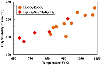 | ||
| Fig. 7 CO2 solubility in molten carbonates at different temperatures at 1.01 × 10⁵ Pa.87 | ||
Fig. 6 shows that molten carbonates also have higher current efficiency at the same current rate, indicating that using carbonates could prevent several side reactions that occur with chlorides, particularly the development of chlorine gas.
Electrolyte compositions can significantly affect the properties of produced carbon in terms of morphology, surface area, pore volume, and conductivity. In Table 3, Deng's research shows that the specific surface area and pore volume of carbon obtained from molten carbonates can be 8 times larger than those from molten chlorides.76 As discussed above, carbonates also hold more remarkable absorption ability and stability. These essential characteristics outweigh their drawbacks, which lead to favouring carbonates over chlorides in molten salt electrolysis. Therefore, the cation selections section focuses on carbonate salts and their related research.
| Molten salt |
I
D![[thin space (1/6-em)]](https://www.rsc.org/images/entities/char_2009.gif) : :![[thin space (1/6-em)]](https://www.rsc.org/images/entities/char_2009.gif) IG IG |
S BET (m2 g−1) | Pore volume (cm3 g−1) | Average pore size (nm) |
|---|---|---|---|---|
| Li2CO3–Na2CO3–K2CO3 | 0.86 | 897.4 | 0.862 | 4.62 |
| 2 mol% Li2CO3–LiCI–KCI | 0.67 | 113.9 | 0.279 | 9.97 |
| 2 mol% Ca2CO3–LiCI–KCI | 0.72 | 157.9 | 0.125 | 3.98 |
| Molten salt | Alkali metal (V) | Carbon (V) |
|---|---|---|
| Li2CO3 | −2.964 | −1.719 |
| Na2CO3 | −2.546 | −2.551 |
| K2CO3 | −2.612 | −3.083 |
| CaCO3 | −3.033 | −1.349 |
| BaCO3 | −3.069 | −1.992 |
Li2CO3 can decompose at temperatures far lower than the melting point, while CaCO3 is chemically stable as its decomposition temperature exceeds its melting point (825 °C).41 As previously discussed, temperatures over 825 °C are more favourable for CO generation than carbon production. Under the same operating conditions, the CO2 capture percentage in CaCl2–CaO can be approximately 17 times higher than in LiCl–Li2O because Ca has higher reduction energy thermodynamically than Li does.67 The relatively low conductivity of BaCO3 and low basicity of BaO can improve the cell voltage during electrolysis and limit anode corrosion.90 But BaCO3 is an uncommon option due to its high cost and toxicity.41
Different cations in carbonates also lead to various carbon nanostructures. Li+ and Ba2+ are expected to promote the formation of CNTs, but K+ hinders the formation of carbon nanostructures.80,91 It is further evidence that electrolytes containing more than 50 wt% of Na or more than 30 wt% K carbonates inhibited CNTs growth but supported the development of carbon nano-scaffolds (CNS).53 Overall, previous studies supported lithium-related salts because of their exceptional qualities.
When Li2CO3, CaCO3 or BaCO3 are used, Li2O, CaO, and BaO are formed as thermal decomposed products. For instance, 1 mol Li2CO3 could generate up to 0.0222 mol Li2O at 750 °C in the air without the influence of electrochemical reactions.80 As shown in Table 4, the voltage required to reduce sodium ions to sodium is close to that required to deposit carbon. Since potassium deposition potential is lower than carbon deposition potential in molten K2CO3, a large portion of electrolysis current would be wasted on reducing potassium if carbon is the desired product. This also suggests the loss of electrolytes when metals deposit on the cathode. Li2O, as a decomposed product or a manual additive, serves as an intermediate for capturing CO2, ensuring continuous operation, and avoiding wasting current on undesired metal deposition. Because Li2CO3 holds a relatively low potential for carbon deposition and a high potential for metal deposition, Li2O can continuously absorb carbon dioxide and form Li2CO3, and regenerate oxides after carbon deposits. In this continuous operation, Li2O is stable as it can avoid being reduced to Li metal as long as the electrochemical window is wisely chosen. Thus, in case Li2CO3 is selected as the electrolyte, carbon would be produced without deposition of metal Li so that the molten salt system remains stable and continuous addition of salts is avoided. This viewpoint was supported by the experimental results that the alkalinity of molten salt Li2CO3–Na2CO3–K2CO3 remained steady during continuous operations, and no Li2O accumulation could be achieved in the system.35 Furthermore, Li+ is a critical component for molten salt electrolysis carbon deposition. Tests on CV performed to track the peaks in carbon reduction provide evidence for this claim. Without Li2CO3, the Na2CO3–K2CO3 electrolysis experiment showed no carbon reduction peak at 750 °C. Adding more CaO enhanced CO2 absorption with a linear correlation of about 1 between metal oxides and CO2.81 However, this conversion was reduced by 20% when the temperature increased from 550 to 600 °C because the carbonation formation is exothermic, which is not favoured at a higher temperature. Li2O was also observed to absorb more CO2 with increasing weight percentage, and the optimum trial reached a maximum of 0.1105 gCO2 gmelt−1, conducted with 8 wt% additive at 923 K under 101.3 kPa.93 However, it should be highlighted that these gas solubility data was obtained without electrolysis, and section 2.2.1 and below contents discuss how metal oxide additives solidify on the cathode and hinder absorption due to additives' poor solubility in electrolytes.
Foreign metal oxides serve as necessary nucleation sites for special carbon nanostructure growths, especially CNTs growth. In fact, one of the most popular research topics focuses on molten salt carbon dioxide capture and electrolysis to produce CNTs and other special nanostructures shown in Fig. 8. Various metal oxides have been tested and examined for carbon nanostructures. Zn or ZnO additives were favourable for carbon nanofiber formation.92 Fe2O3 is another popular additive. In some cases, the electrodes contain transition metals that can be reduced to metal elements during electrolysis.44,55 These transition metals helped the growth of the tip, and the end of a CNT as TEM HAADF showed evidence of metal inside CNT and the two ends.44 Another interesting case is that Fe ions could successfully combine with produced carbon to synthesize MWCNT/Fe3C nanomaterial at 900 °C under 3.1 V with iron melt in the electrolytes.94 GeO2 is another example.95 Soluble GeO2 was electrochemically reduced to Ge and deposited on the cathode with carbon, and during this process, Ge anchored on the ends and the inner wall of formed carbon to grow carbon nanotubes. Considering Chen's proposed theories about how additives' solubility affects reaction mechanisms using CaO and BaO, the key factor for CNTs formation may depend on the solubility of additives in electrolytes. Overall, one possible theory is that metal oxide additives are reduced to metal and then serve as the active sites for the formation of carbon nanotubes or nanofibers.44,55,92,94,95
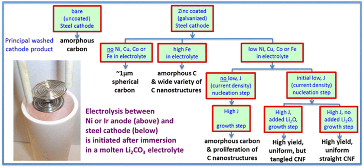 | ||
| Fig. 8 Molten carbonate electrolysis pathways converting CO2 leading to high yield, uniform CNF product.92 | ||
In addition to metal, oxygen ions in these additives need to be examined since they play a significant role in the splitting reaction and regulate the rates of many reactions, such as the evolution of oxygen on the anode surface and the conversion of CO2 to CO32−. Therefore, there exists an optimal quantity of additives that should be applied to each system. Metal oxides are crucial for supplying oxygen ions when molten chlorides are applied as electrolytes. There is no carbon deposition detected in the absence of metal oxide additives.78 The metal oxide additives enable not only to capture CO2 and to initiate the subsequent carbon deposition but also to introduce significant defects into final carbon products (e.g. CNT),41,80,83 The introduction of over-dosed O2− has a drawback on CNTs formation. 30 wt% BaO with 0.04 wt% Fe2O3 and 0.04 wt% Cr2O3 additives led to 20% CNTs yield, which was about 10% higher than 7.1 wt% BaO but 60% less than using 0.1 wt% of Fe2O3. Deng reported that the CaO additive was solidified and covered the cathode when O2− was over-dosed.81 As shown in eqn (1), the electrolysis of carbonate ions produces 3 units of oxide ions. These oxide ions near the cathode can easily bond with metal cations to form metal oxides. Solidified CaO showed poor CO2 absorption, and the covered cathode lost activity. Moyer et al. also reported that Li2O build-up at the cathode lowered the reaction and decreased the carbon graphitization degree.66 Gao's article provides another explanation that external O2− from dissolved oxide additives lowers the O2− concentration gradient in the electrolyte, and thus it slows the diffusion and limits the electrolysis rate.64 Additional research must be conducted to fully comprehend.
Therefore, researchers also attempted to manage oxygen ion products and continuously remove them instead of increasing oxygen ions in the system to capture CO2. Yet LiBO2 has been reported to be an effective additive. BO2− acts as an O2− absorbent and converts into BO33−, which later reacts with CO2 to produce CO32− and BO2−.57 The CO2 concentration was reduced from 14% to 7%. The LiBO2 free electrolytes presented a CO2 concentration drop of 2.1%, only one-third of the concentration drop in LiBO2 electrolyte.57 The reduction potential was reduced by 400 mV in this attempt, which resulted in a lower applied voltage at the same current density and a 60% reduction in energy consumption.
2.3 Electrodes
The two crucial elements in this electrolysis system are the anode and cathode, which are responsible for oxygen evolution and carbon deposits, respectively. Therefore, the anode must promote oxygen generation, while the cathode should have active areas for particular carbon nanostructures. Both electrodes nonetheless share some characteristics in common, such as resistance to corrosion in hostile situations with molten salts.Through the CO2 splitting reaction, the changes on electrodes cause current fluctuation and unstable performance; thus, it is important to avoid corrosion due to molten salts or oxygen evolution effects on electrodes. Corrosion of carbonates can even dissolve the alumina or zirconia container.72 Corrosion easily alters electrode surface and compositions. When the effective anode area significantly decreases, the current density can have a 66% drop.67 While formed carbon expanded on the cathode surface, the current density increased.81 Even when the used Ni electrode seemed unchanged, as observed by eyes, the green residue in the electrolyte indicated part of Ni was oxidized and escaped.96 More stable metals, alloys or oxides should be utilized to minimize corrosion, such as NiCr alloy and TiO2.
Iron is earth-abundant, affordable metal and has incredible influences on carbon products. During electrolysis, a stainless steel cathode releases Fe and other alloying metals, including Ni and Cu.100 These ions result in a micro explosion and help form graphene when CO is produced. Douglas's research group manipulated the CNTs sizes by adjusting Fe sizes, as shown in Fig. 9.101
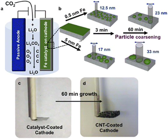 | ||
| Fig. 9 Schematic illustrations: (a) electrolysis setup, (b) catalyst of varying thickness and growth time controlling the CNT diameters, (c) catalyst-coated stainless-steel cathode before, (d) after 60 min growth of CNTs.101 | ||
In addition to Fe, a copper cathode enhances the formation of a unique ball structure of graphene, while a nickel cathode leads to flat graphene sheets. The various carbon nanostructures indicate the active metal atoms on the cathode act as the nucleation sites and catalyse the development of carbon films.100 Ti is another suitable material as Ti is chemically stable in molten salts, and the formed oxide layer, TiO2 or LiTiO2, is also conductive and insoluble up to 900 °C in Li2CO3 and Li2O.72 Zn is another case of how cathode metal alters carbon nanostructures. Zn galvanized steel cathode surface generates a high percentage (over 80%) of carbon nanofibers, which cannot be achieved by using 316 stain steel cathode.92 One way to explain these experimental observations can be through the density functional theory.97 It showed that the π–d bond between the metal particles and nanotubes encouraged the nanotube growth, and the overlap of the d orbitals from Zn and Ni could improve the nanotube quality.97 However, the interaction of oxygen ions and metals was not considered, including the formation of metal oxides and the solubility of metals and metal oxides.
Graphite is not a good cathode choice as it quickly swells and decomposes due to electrolyte metal intercalation, even under a low cathode current of 30 mA cm−2.72 Additionally, the CV scanning results showed that carbon triple bonds were electrochemically converted into carbon, which is more difficult on graphite than metals such as Ni.102
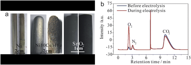 | ||
| Fig. 10 (a) Digital photos of Ni, Ni10Cu11Fe and SnO2 electrodes before and after serving as the anode; (b) gas chromatograms of the outlet gas before and during electrolysis using the SnO2 anode.35 | ||
Metals own satisfying conductivity, but their poor durability seriously limits their applications. The anodic dissolution order of metals in molten CaCl2–CaO was Fe, Cu, Co, Ag, Ni, Mo, and Pt, shown in Fig. 11. A higher polarization current density at a potential indicates the dissolution of such metal is faster. Thus, Pt has outstanding stability among all these pure metals. Pt's superior performance was proved again in the anodic polarization curve in molten Li2CO3–Na2CO3–K2CO3. However, the high price of this noble metal hinders its real-world application.
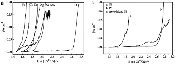 | ||
| Fig. 11 (a) Polarization curves of metals in molten CaCl2 – 2.5 mol% CaO at 850 °C (potential scan rate, 2 mV s−1); (b) polarization curves of Ni, Pt and pre-oxidized Ni in molten CaCl2 at 850 °C (potential scan rate, 2 mV s−1).103 | ||
Metal oxides were investigated as anode materials, targeting high corrosion resistance and lower prices compared to Pt. Ni is of great interest to scientists because it naturally generates a NiO top surface layer with more resistance.92Fig. 11(b) shows NiO could have comparable resistivity to Pt. Other Ni-containing materials, such as (1−x)CaTiO3–xNi, have been studied. Among them, 0.5CaTiO3–0.5Ni and 0.4CaTiO3–0.6Ni materials present satisfying anodic and stable performance with a corrosion rate of 4.958 × 10⁻³ g cm−2 h−1.104 However, Du et al. pointed out that temperature played an important role in influencing the formation of a Ni oxidized layer on the Ni anode. At a temperature lower than 575 °C, LixNi1−xO was the main oxidization product, which is soluble in the carbonate electrolytes. Only at temperatures above 575 °C could an evenly distributed, insoluble, and robust NiO layer form, which could shield the anode from further oxidation.
Other metal oxides also show a positive possibility of being applied as an anode, including SnO2, RuO2–TiO2, and Ti4O7. Among the mentioned metal oxides, the SnO2 anode shows similar polarization curves compared to Pt and Ir and becomes a popular anode choice.35Fig. 10(a) presents the photos of a SnO2 electrode before and after the electrolysis, where no obvious mass loss is observed. In an extreme case of 500 hours electrolysis, the SnO2 anode lost less than 0.1 wt%.35 However, the polarization curve slopes of SnO2 are less significant than those of Pt and Ir, indicating the oxide has a worse oxygen evolution activity on SnO2.105 RuO2–TiO2 was employed in molten chlorides, and there were no physical changes observed after a 4 hour operation.106 But Ru is also a noble metal on Earth, and Ti oxides lack stability compared to other oxides.105 Additionally, there is a lack of records for RuO2–TiO2 performances in molten carbonates.
Alloys can also be promising anode materials thanks to their satisfying properties. Compared to metal oxides, alloys have better conductivity and malleability; alloys also show better corrosion resistance compared to pure metals. Ni-based alloys are the most popular anodes used in carbonate electrolytes.49,58,60,91,101,104 Ni alloy can have two roles based on different metal atoms: a NiO layer as a protective layer is formed during the electrolysis. In contrast, other metal particles in the alloy are believed to catalyse different carbon nanostructures. Ni10Cu11Fe is one example of this alloy strategy. By observing with eyes, the oxidized layer of NiO occurred on the anode surface due to the specific green colour of NiO, different from other oxides or metals, but there was no dimension change of the anode observed after over 100 hours electrolysis.60 Another case for Ni alloy is Ni–Cr alloy, where NiO is still the leading protective layer against corrosion.49 Cr2O3, the oxide form of Cr in the alloy, cannot be detected, which again indicates NiO acts as the protective layer and remains during the electrolysis.49 Besides the protective surface strategies, other types of alloys are applied to investigate the effects of metal particles on carbon nanostructures. Fe materials were also tested previously for anode performances. Incoloy, an Iron-based alloy with over 40% iron content, released Fe ions into the system when it was used as an anode.55 Because the iron content is large in Incoloy, the released Fe ion amount was significant, which combined with carbon and formed iron carbide on the CNTs external walls, resulting in a magnetic carbon material.55
In some cases, a solid electrolyte is utilized as an anode to act as an oxygen ion conductor. ZrO2 was expected to fasten oxygen evolution.67 The anode contains a ZrO2 tube filled with carbon power to enhance electrical conductivity, and a stain steel pipe inserts in the carbon power and connects to a power supply.67 However, the experimental results were far from satisfying. The conductive carbon diffused in the ZrO2 lattice and reacted with oxygen to reproduce CO2.67 Thus, the reason for unsatisfying CO2 conversion could be the technical design of the anode.
It Is also worth mentioning that simply increasing the anode surface largely helped the oxygen ion mass transfer, reduced oxide build-up on the cathode surface, and controlled CNTs size, as shown in Fig. 12.66 Notably, the ratio of 20![[thin space (1/6-em)]](https://www.rsc.org/images/entities/char_2009.gif) :
:![[thin space (1/6-em)]](https://www.rsc.org/images/entities/char_2009.gif) 1 was not favoured for CNTs growth, which can be explained by the dramatic area difference between the electrodes. The noteworthy difference resulted in a mismatched electric field, leading to low current efficiency.
1 was not favoured for CNTs growth, which can be explained by the dramatic area difference between the electrodes. The noteworthy difference resulted in a mismatched electric field, leading to low current efficiency.
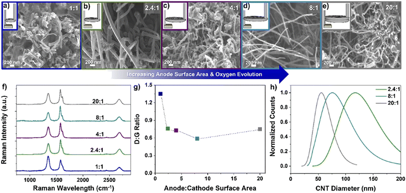 | ||
Fig. 12 Different anode to cathode surface area ratios (A![[thin space (1/6-em)]](https://www.rsc.org/images/entities/char_2009.gif) : :![[thin space (1/6-em)]](https://www.rsc.org/images/entities/char_2009.gif) C) and the resulting carbon product using a Ni/Al2O3 anode with 5 nm Fe on stainless steel cathode; a) 1 C) and the resulting carbon product using a Ni/Al2O3 anode with 5 nm Fe on stainless steel cathode; a) 1![[thin space (1/6-em)]](https://www.rsc.org/images/entities/char_2009.gif) : :![[thin space (1/6-em)]](https://www.rsc.org/images/entities/char_2009.gif) 1, b) 2.4 1, b) 2.4![[thin space (1/6-em)]](https://www.rsc.org/images/entities/char_2009.gif) : :![[thin space (1/6-em)]](https://www.rsc.org/images/entities/char_2009.gif) 1, c) 4 1, c) 4![[thin space (1/6-em)]](https://www.rsc.org/images/entities/char_2009.gif) : :![[thin space (1/6-em)]](https://www.rsc.org/images/entities/char_2009.gif) 1, d) 8 1, d) 8![[thin space (1/6-em)]](https://www.rsc.org/images/entities/char_2009.gif) : :![[thin space (1/6-em)]](https://www.rsc.org/images/entities/char_2009.gif) 1, e) 20 1, e) 20![[thin space (1/6-em)]](https://www.rsc.org/images/entities/char_2009.gif) : :![[thin space (1/6-em)]](https://www.rsc.org/images/entities/char_2009.gif) 1 and f) Raman spectra, g) D 1 and f) Raman spectra, g) D![[thin space (1/6-em)]](https://www.rsc.org/images/entities/char_2009.gif) : :![[thin space (1/6-em)]](https://www.rsc.org/images/entities/char_2009.gif) G ratio, and h) CNT diameter distribution at ratios of 2.4 G ratio, and h) CNT diameter distribution at ratios of 2.4![[thin space (1/6-em)]](https://www.rsc.org/images/entities/char_2009.gif) : :![[thin space (1/6-em)]](https://www.rsc.org/images/entities/char_2009.gif) 1, 8 1, 8![[thin space (1/6-em)]](https://www.rsc.org/images/entities/char_2009.gif) : :![[thin space (1/6-em)]](https://www.rsc.org/images/entities/char_2009.gif) 1, and 20 1, and 20![[thin space (1/6-em)]](https://www.rsc.org/images/entities/char_2009.gif) : :![[thin space (1/6-em)]](https://www.rsc.org/images/entities/char_2009.gif) 1.66 1.66 | ||
2.4 Temperature
Temperature plays a critical role in electrolytic processes, product compositions, and material structures of produced carbon. For example, CNTs are more likely to form at operation temperatures lower than 700 °C, while CNS or CO favours higher temperatures.53Fig. 5 describes how temperatures and voltages affect the reactions.74 Under the same potential, different reactions are thermodynamically favourable at different temperatures.Temperature easily changes electrolyte properties, which later affects CO2 absorption and conversion. Increasing temperature leads to a reduction in the stability of carbonates and CO2 solubility.67 Increasing temperatures shift the decomposition equilibrium towards the product side, producing more metal oxides and CO2. The CO2 volumetric mass transfer coefficients in carbonates decreased with increasing temperature, which negatively influences CO2 physical dissolution.89 CO2 chemical dissolution, specifically the formation of CO32− in eqn (3), is also weakened with increasing temperatures. For carbonates, it is even worse as heat decomposition results in related instability and then decreases CO2 solubility with increasing temperatures.67 In addition, the diffusion rate of carbonate ions directly corresponded to temperatures, which obeyed Arrhenius' Law.107 An experimental data sample is shown in Table 5. Based on the data and Arrhenius' Law, the activation energy is calculated to be 35.8 kJ mol−1. It is also revealed that temperature effects on CO32− diffusion are relatively small.
| Temperature (K) | D × 105 (cm2 s−1) |
|---|---|
| 973 | 4.46 |
| 993 | 4.82 |
| 1023 | 5.31 |
| 1043 | 5.90 |
| 1063 | 6.54 |
The increased temperature can bring some negative effects to the electrolysis. The electrical resistance of electrolytes typically decreases as temperature increases.71 For example, the current increased by 500 mA from 550 °C to 650 °C, and carbon layers were produced faster and thicker as the kinetics and diffusion rate increased.71 Other researchers pointed out that lower salt resistance did not necessarily mean higher current efficiency (Table 6).73 The maximum current efficiency remains stable under varying temperatures but varies at different voltages. Thus, the optimal operation conditions require further investigation to determine.
| Voltage (V) | Temperature (°C) | Time (h) | Deposition rate (g cm−2 h−1) | Current efficiency (%) |
|---|---|---|---|---|
| 3 | 540 | 1.0 | 0.0306 | 91 |
| 3 | 593 | 1.0 | 0.0306 | 92 |
| 3 | 700 | 1.0 | 0.0613 | 90 |
| 4 | 540 | 1.0 | 0.0917 | 99 |
| 4 | 593 | 1.0 | 0.0851 | 100 |
| 4 | 700 | 1.0 | 0.0488 | 85 |
| 5 | 540 | 1.0 | 0.0712 | 98 |
| 5 | 593 | 1.0 | 0.0665 | 88 |
| 5 | 700 | 1.0 | 0.0248 | 65 |
| 5 | 540 | 0.5 | 0.1107 | 78 |
| 5 | 593 | 0.5 | 0.0874 | 89 |
| 5 | 700 | 0.5 | 0.0400 | 73 |
Monitoring temperature can help achieve the desired structure and composition of carbon products. With the same operating conditions except for temperatures, a honeycomb structure of carbon was observed at 577 °C, but nanotubular carbon was obtained at an elevated temperature above 600 °C.91 Another similar case was the carbon nanostructures changed under 2.6 V, and temperature varied from 650 °C to 850 °C.100 At 650 °C, the produced carbon was thick graphite. With the temperature increasing to 750 °C, flat graphite sheets with graphene were observed. A further increase in temperature to 850 °C resulted in flatter sheets of graphene with fewer layers.100 An increasing temperature also encourages the development of CNTs and suppresses the growth of CNS when transition metals, such as Ni, Cr, and Fe, are used as catalysts.53 As shown in Table 7, combustion activation energy decreased with increasing operation temperature under the same voltage supply. As the energy barrier decreases with higher temperature, it is easier for carbon to deposit on the cathode, which matches the increased deposition rate in Table 6. This lower energy barrier could also explain why smaller carbon particle sizes were obtained.73 From Table 8, it is seen that increasing operating temperatures resulted in higher carbon contents and lower O, Fe, and K contents, except for Cr. Higher voltage and temperature surprisingly had a passivation effect on the anode, reducing Cr and Fe contents in the carbon.73
| Temperature (°C) | Cell voltage | ||
|---|---|---|---|
| 3.0 V | 4.0 V | 5.0 V | |
| E a (kJ mol−1) | |||
| 540 | 158 | 165 | 171 |
| 593 | 152 | 158 | 160 |
| 700 | 131 | 142 | 148 |
| Element | Weight% | ||
|---|---|---|---|
| (a) Cell voltage | 3.0 V | 4.0 V | 5.0 V |
| C (K) | 83.39 | 85.20 | 88.54 |
| O (K) | 12.80 | 13.85 | 10.71 |
| K (K) | 0.55 | 0.28 | 0.45 |
| Cr (K) | 1.20 | — | — |
| Fe (K) | 2.07 | 0.68 | 0.47 |
| (b) Temperature (°C) | 540 | 593 | 700 |
| C (K) | 83.56 | 85.20 | 92.33 |
| O (K) | 13.46 | 13.85 | 5.65 |
| K (K) | 1.12 | 0.28 | 1.73 |
| Cr (K) | 0.79 | — | — |
| Fe (K) | 1.83 | 0.68 | 0.28 |
Not only the electrolysis temperature but the drying temperature following the washing could change the composition of the products. Washed carbon samples were dried at 80, 400, and 1000 °C, and it is reported that carbon nanoparticles at 400 °C contained the highest surface area detected by BET and the largest Li and Na capacity amounts, providing superior electrochemical performances.70 It is also found that the in-plane layer stacking dimension decreases gradually from 74 nm at 80 °C to 29 nm at 1000 °C.70
2.5 Voltage & energy efficiency
The voltage of the system has an impact on the contents and the morphology of the products. As shown in Fig. 5, voltage is as important as temperature, and both play a significant role in determining the electrolysis reaction. However, a higher voltage supply also indicates large energy consumption. Considering the energy costs, the balance of product quality and operation settings needs to be carefully maintained to achieve the optimum profit. Additionally, the voltage should be carefully balanced: sufficient current enlarges carbon deposition rate while higher current results in a strong electric field and leads to difficult carbonate anion diffusion towards the cathode; Table 6 shows a decrease in deposition rate when the voltage increased from 4 to 5 V at 540 °C. The behaviour can be explained by the formation of CO, but the influence of the electric field on the diffusion of carbonate ions has not been investigated.The electrolysis voltage should vary depending on the electrolyte cations and the amount of energy needed to split carbonates at a particular temperature. To minimize impurities in carbon products, the voltage, in general, should be less than the theoretical deposition potential of alkali cations or chloride evolution of electrolytes. Taking Li2CO3 electrolyte as an example, the applied voltage should be controlled between −2.964 and −1.719 V at 600 °C to produce carbon and avoid Li formation using data from Table 4. However, this range is not mandatory in practice, which means the voltage setting can exceed the potential of alkali metal formation. Numerous research studies were conducted under much higher voltage. It is believed that, under an operating voltage higher than alkali deposition potential, the deposited alkali metal particles can act as nucleation sites and encourage the growth of unique nanostructures. Ge, Ni, Fe, and other metals were observed in SEM or TEM to grow CNTs by serving as two ends of the tube structure.44,95
Similar to how they can be modified by temperature, the compositions and architectures of the products can also be altered by voltage. It is common knowledge that at a current between 0–2 A cm2, CO2 converts into carbon, and no gas is generated at the cathode, while a higher current can lead to the formation of CO gas.108 With the extremely large current of 33 A, nano-diamonds could be produced at low pressure at 800 °C.109 At 2.8 V, the carbon product appears to be a carbon film. When the voltage increases to 4.0 V, the carbon presents a flocculent exterior.35 Carbon, as well as alkaline metal depositions, decide the final nanostructures of formed carbon, especially at a high cell voltage (over 5 V).71 The SEM images of the carbon obtained at different voltages are shown in Fig. 14. As shown in Table 9, the specific surface area of carbon increases with increasing voltages. Similar results are also observed in Ijije's article.73 The particle sizes of carbon become smaller with rising current densities.91 However, the crystallinity of carbon does not change with voltage. Kaplan and his colleagues operated the experiments under −1.6, −2.4, and −6.0 V remaining other parameters the same.108 From Kaplan's data, the crystallinity of carbon products was similar but slightly reduced when the voltage became more negative. Along with more negative voltage, the side reactions play a more important role. The carbon samples grow more impurities, including oxygen and lithium.108 The weight percentage changes aligned with the theories of alkali metal deposition are expressed in eqn (6). Mesopores increase with elevated voltage.73 Additionally, a combination of high and low current densities in the process can lead to different carbon nanostructures. For instance, amorphous carbon is obtained if the current density is kept at 100 mA cm−2 for the cathode throughout the process. While CNF is formed when the current density is set low initially, e.g., 5 mA cm−2 for 1 h, and gradually increases to 100 mA cm−2 and remains at this density.92 Ren et al. suggested the difference in carbon nanostructure is caused by the anode metal deposition at low current density, such as Ni, which is critical for CNF nucleation formation.92
| 3.5 V | 3.0 V | 4.0 V | 4.5 V | 5.0 V | 5.5 V | 6.0 V | |
|---|---|---|---|---|---|---|---|
| 450 °C | 306.76 | 558.10 | 536.41 | 613.76 | 526.60 | 868.31 | 856.26 |
| 550 °C | — | — | — | 212.39 | — | — | — |
| 650 °C | — | — | — | 101.89 | — | — | — |
The activity of oxygen ions is also affected by voltages. Fig. 13 shows the Chrono-potentiometric plots for the anodic oxidation of carbon. The rapid increase in the current between the second and third plateaus demonstrates the activity of oxygen ions in the molten salt is slower than the activity of CO32−. The CVs Ijije and his team obtained show there was no clear signal of anodic discharge of the O2− ions, which also indicates the amount of O2− ions generating O2 is less than the amount of O2− ions produced by carbonate ion splitting.41 The loss of oxygen ions can be explained by eqn (3), where the O2− ions absorb carbon dioxide and form carbonate ions. However, how different voltages influence the O2− transfer and oxygen generation has not been fully reported yet.
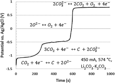 | ||
| Fig. 13 Chrono-potentiometric plots for anodic oxidation of the electro-deposited carbon in Li2CO3–K2CO3 at 574 °C, reproduced from ref. 41 with open-access permission from the Royal Society of Chemistry, copyright 2014. | ||
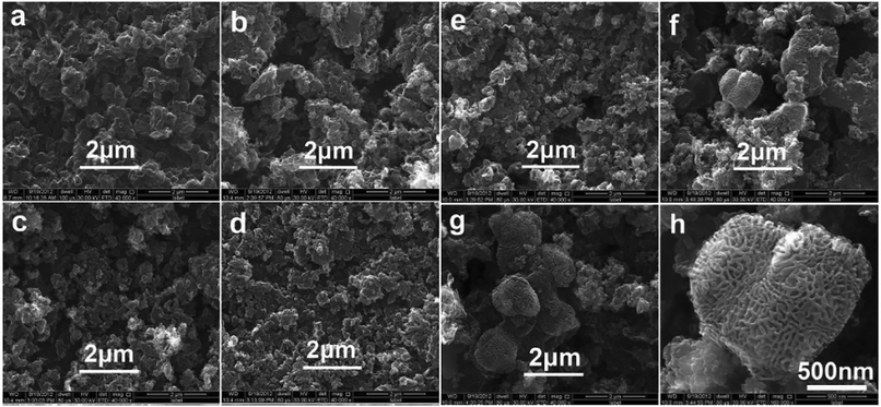 | ||
| Fig. 14 SEM images of carbon powders obtained under cell voltages of 3.0 V (a), 3.5 V (b), 4.0 V (c), 4.5 V (d), 5.0 V (e), 5.5 V (f), (h) and 6.0 V (g) at 450 ° C in Li2CO3–Na2CO3–K2CO3 mixture.71 | ||
The required voltage is directly associated with current efficiency and energy consumption. Although high voltage may result in a desirable morphology of carbon product, the energy penalty might overweight the improvement. Fig. 15 shows the highest temperature or voltage is not the optimal condition for reaction efficiency or energy consumption. Temperature and voltage should be selected for best efficiency, preferred carbon structure, and affordable energy consumption. Harsh operation conditions are always accompanied by excessive energy consumption. Tang's research results demonstrate the lowest energy consumption was around 38 kW h kg−1 CO2 at 3 V and 550 °C, which aligned with Yin's finding.35,71 It should be emphasised that their calculations of energy consumption did not account for the heat needed to maintain high temperatures. Lack of heat consumption could result in mistakes when determining the best operating conditions because temperatures and voltages both affect how quickly carbon is deposited. Most importantly, more research should be conducted in the future to determine how voltage affects carbon deposition rate and its nanostructures.
 | ||
| Fig. 15 Energy consumption and current efficiency under different cell voltages at 450 °C (a), 550 °C (b), and 650 °C (c).71 | ||
2.6 Composition of inlet gas
Power plant flue gas usually contains various gas components, and their compositions are changed with combustion conditions.110,111 CO2, O2, SO2, NOx, and vapour are commonly identified in the flue gas. Molten salt electrolysis has been performed under various CO2 concentrations, ranging from 0.04% (atmospheric concentration), 14% (typical CO2 concentration in the flue gas), to 100%.35,57,92 It is unnecessary to concentrate CO2 prior to electrolysis. It was reported that half of the CO2 can be absorbed from gas with 14% CO2 and converted into carbon with 90% current efficiency.57 Even for 0.04% carbon dioxide concentration, the centration step is not required, and current efficiency can still be near 100%.92However, other gas impurities' effects have not been fully reported. Investigating how these impurities affect the electrolysis reaction and products is required before applying this electrolysis approach to commercial post-combustion plants. N2, as an inert gas, is often used as the carrier gas for flow rate and pressure modifications. However, O2-related effects have not yet been fully observed. The influence of vapour was carried out using LiOH additives as an alternative because of the difficulty in the quantification of vapour added to the system.48 Under a typical operating condition of molten salt electrolysis, vapour has a good chance of undergoing the water-splitting reaction, which expects to have a significant impact on the electrolytic process.47,48,112 Shown in Table 10, H2 is the major product, over 50% in all cases, when CO2 is fed into molten carbonates with LiOH additives. With appropriate conditions, the current efficiency for syngas could achieve 90%.112 Ji's report shows similar results that an increase of 0.5 V significantly promoted CO formation and resulted in 33.6% CO and 64.2% H2 in the gas products.48
| No. | Electrolysis parameters | Gas content | |||
|---|---|---|---|---|---|
| Temperature (°C) | Voltage (V) | CH4 (%) | CO (%) | H2 (%) | |
| 1 | 450 | 2.0 | 18.2 | — | 81.7 |
| 2 | 500 | 2.0 | 22.1 | — | 88.6 |
| 3 | 550 | 2.0 | 40.1 | — | 59.5 |
| 4 | 600 | 2.0 | 30.4 | 0.1 | 69.3 |
| 5 | 650 | 2.0 | 27.3 | 2.4 | 69.9 |
| 6 | 550 | 1.0 | — | — | 100 |
| 7 | 550 | 1.5 | — | — | 100 |
| 8 | 550 | 2.5 | 13.3 | 9.2 | 77.2 |
| 9 | 550 | 3.0 | 5.4 | 20.2 | 74.0 |
| 10 | 550 | 3.5 | 1.9 | 33.6 | 64.2 |
SO2 in the flue gas undergoes electrolysis in the molten carbonate salt with Li2SO4 additive. Similar to CO2, SO2 can react with O2− and form Li2SO4, which is later reduced into sulfides or sulphur. The resulting sulphur is inserted into deposited carbon nanostructures, forming sulphur-doped carbon.79 Instead of accumulating in molten salts, it is observed that sulphur element was found at the gas outlet of the cathode.113 Sulphur contents in the system can also react with carbon to form CS2, which is helpful in removing imperfect carbon and leads to graphitization over 500 °C. It suggests that the deposited S and S2− also contribute to the low-temperature graphitization.114 In the end, sulphur contents in the feed stream can be completely captured.34
Eqn (14) and (15) are the two possible reactions happening in Li carbonate molten salts.113 Li2SO4 has lower decomposition potentials compared to Li2CO3, so the sulphur reduction current is limited by diffusion.113 CO2 can still be converted into carbon or CO, but with reduced efficiency; for example, the CO production faradaic efficiency with SO2 inlet is reduced to 54%, as shown.113
| 4Li2CO3 + 4SO2 → Li2SO4 + Li2S + 4CO2 | (14) |
| 4Li2O + 4SO2 → 3Li2SO4 + Li2S | (15) |
| 2Li2CO3 + 2SO2 + O2 → 2Li2SO4 + 2CO2 | (16) |
| 2Li2O + 2SO2 + O2 → 2Li2SO4 | (17) |
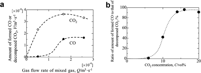 | ||
| Fig. 16 (a) Amounts of decomposed CO2 gas and produced CO gas as a function of inlet gas flow rate; (b) ratio of the amount of formed CO gas to that of decomposed CO2 gas as a function of the initial gas concentration of CO2.42 | ||
3 Conclusion & future challenges
Molten salt CO2 electrolysis is an innovative CO2 capture and conversion method targeting power plant flue gas to achieve CO2 zero emission. This molten salt system presents multiple advantages, including high current efficiency, simper solid separation of produced carbon, engineered carbon nanostructures, and positive cash flow. Carbonates hold better CO2 absorption ability and higher current efficiency compared to chlorides as electrolytes. Considering metal deposition side reactions and melting points, lithium, sodium, and potassium carbonates are widely used and combined. Oxide additives are favoured to increase gas sorption, especially in chlorides, and also impact carbon nanostructures. The cathode is another factor influencing carbon nanostructures, and popular choices are Fe, Ni, Pt, their metal oxides, and alloys. Anode is responsible for the critical oxygen evolution so the materials should have a strong durability and anti-corrosion ability, such as metal oxides and alloys. Temperature and voltages are the two significant parameters in this electrolysis, as they control the activation energy of the electrolysis. Higher temperature suppresses carbon formation but improves CO production. The study of voltage focuses on not only the electrolysis potentials but also the energy consumption for optimal efficiency.However, molten salt CO2 electrolysis leaves some research gaps. The first challenge is scaling up and corrosion's effects on the equipment. To date, all the research results are produced from a lab-scaled system, and there has not been a commercial-scaled system yet. The mass and energy balance, energy efficiency, cost of materials, the activity of electrocatalysts, waste heat utilization, and system designs are unknown or obscure engineering aspects.74 There exist obstacles in maintaining a continuous operation, recovering salts, and removing carbon that has grown on the cathode. Although Licht's research team did suggest a method for separating salt electrolytes, some problems still appear to prevent the commercialization of electrolysis. These problems include the energy loss associated with preheating the separation device to 750 °C, carbon build-up on the cathode surface, and potential device corrosion.45 For the recovery process and saving acid from dissolving carbonates in current lab-scale experiments, a molten CaCl2 dissolver was proposed to extract carbon from CaO and CaCO3, which are insoluble in water.115 But the corrosion tests of this method should be obtained to compare the influence of CaCl2 and other soluble carbonates. Furthermore, equipment and electrodes can corrode rapidly due to high temperatures and the corrosive nature of molten salts under general electrolysis operations. More research is therefore needed to develop reliable electrodes that are more affordable, perform better, and balance absorption kinetics and reaction mechanisms. To enhance CO2 conversion efficiency, the shape and surface area of electrodes should be investigated.
The formation of uniform carbon nanostructures can be another challenge. Morphology of carbon products is sensitive to operating conditions; for example, MWCNTs took up 40 vol% of Novoselova's cathode sample and about 80% CNFs in Ren's results.81,98 In the latest report, the highest percentage of a specific nanostructure was 98%.44 A 100% uniform carbon nanostructure has not been obtained. In addition to the carbon nanostructure, it is important to investigate the carbon deposition rate with different additives. Furthermore, these reports made no comment on the factors that affect the rate of carbon deposition or the effectiveness of CO2 capture; hence, further research is necessary to close this knowledge gap.
More fundamental research is required to fully understand the electrolysis reaction mechanisms, such as quantifying oxides and carbonate ion concentration changes and their mass transfer. Although the operating parameters and their effects on electrolysis performances and products have been investigated, there are still some challenges, such as quantifying rate-determining step and monitoring oxygen ion mass transfer during electrolysis and CO2 absorption. The influences of the electric field on carbonate anions should also be examined to study the diffusion mechanism of carbonate anions towards the cathode. The density functional theory (DFT) has been employed to interpret the fundamentals of metal particles as nucleation sites for the formation of nano carbon products.97 Experimental validations are essentially expected. More DFT research and calculation should be performed to provide a more comprehensive study of different parameters and conditions at the molecular level. There also lacks records for a full analysis of the effects of flue gas impurities, especially for NOx, water vapour, and oxygen. Besides its compositions, the conditions of the flue gas, including pressure and temperature, have not been well studied. Other fundamental knowledge deserves attention, including electrode/electrolyte interface analysis, mass transfer between gaseous CO2, liquid electrolytes, and solid electrodes, reactors' influences on electrolysis, CO2/electrolyte fluid dynamics, and more. Other basic analysis, such as safety and economy analysis, is also missing in this field.
Conflicts of interest
The authors declare no conflict of interest.Acknowledgements
The authors would like to acknowledge the financial support received from Natural Resources Canada (NRCan) CCUS program and Western University Ontario.References
- R. A. Smith, Air and rain: the beginnings of a chemical climatology, Longmans Green and Co., London, 1872 Search PubMed.
- G. Nonhebel, A commercial plant for removal of smoke and oxides of sulphur from flue gases, Trans. Faraday Soc., 1936, 32, 1291–1296 RSC.
- OECD, 20 Years of Carbon Capture and Storage: Accelerating Future Deployment | OECD iLibrary, [cited 2023 May 8], Available from: https://www.oecd-ilibrary.org/energy/20-years-of-carbon-capture-and-storage_9789264267800-en Search PubMed.
- H. Herzog, An Introduction to CO2 Separation and Capture Technologies, MIT Energy Laboratory, 1999, pp. 1–8, [cited 2023 May 8], Available from: https://sequestration.mit.edu/pdf/introduction_to_capture.pdf Search PubMed.
- OECD/IEA, Prospects for CO2 Capture and Storage – Analysis, IEA, [cited 2023 May 8], Available from: https://www.iea.org/reports/prospects-for-co2-capture-and-storage Search PubMed.
- J. Farrell, Carbon Capture -- CCS: how regulatory, technological, and legislative failures have dogged the carbon mitigation strategy throughout the decades, Journal of Science Policy & Governance, 2018, 12(1), 1–22 Search PubMed.
- A. Midttun, The Negotiated Political Economy of a Heavy Industrial Sector: The Norwegian Hydropower Complex in the 1970s and 1980s, Scan. Polit. Stud., 1988, 11(2), 115–144 CrossRef.
- J. Zillman, A History of Climate Activities, 2015, [cited 2022 Oct 18], Available from: https://public.wmo.int/en/bulletin/history-climate-activities Search PubMed.
- H. Ritchie and M. Roser, CO2 and Greenhouse Gas Emissions, Our World in Data, 2020, [cited 2022 Sep 19], Available from: https://ourworldindata.org/emissions-by-sector Search PubMed.
- IEA, Global Energy Review: CO2 Emissions in 2021, IEA, 2021, [cited 2022 Oct 18], Available from: https://iea.blob.core.windows.net/assets/c3086240-732b-4f6a-89d7-db01be018f5e/GlobalEnergyReviewCO2Emissionsin2021.pdf Search PubMed.
- R. Shirmohammadi, A. Aslani, R. Ghasempour and L. M. Romeo, CO2 utilization via integration of an industrial post-combustion capture process with a urea plant: Process modelling and sensitivity analysis, Processes, 2020, 8(9), 1144 CrossRef CAS.
- D. Kearns, H. Liu and C. Consoli, Technology readiness and costs of CCS, 2021, [cited 2022 Oct 18], Available from: https://www.globalccsinstitute.com/wp-content/uploads/2021/04/CCS-Tech-and-Costs.pdf Search PubMed.
- SCCS, Sleipner Details, [cited 2022 Sep 26], Available from: https://www.geos.ed.ac.uk/sccs/project-info/2 Search PubMed.
- SaskPower, Carbon Storage Research Centre, SaskPower, [cited 2022 Oct 18], Available from: https://www.saskpower.com/our-power-future/infrastructure-projects/carbon-capture-and-storage/carbon-storage-research-centre Search PubMed.
- Alberta Government, Quest Carbon Capture and Storage project: annual report, 2020 - Open Government, 2020, [cited 2022 Jul 16], Available from: https://open.alberta.ca/publications/quest-carbon-capture-and-storage-project-annual-report-2020 Search PubMed.
- Province of British Columbia, British Columbia's Carbon Tax, Province of British Columbia, [cited 2023 Feb 28], Available from: https://www2.gov.bc.ca/gov/content/environment/climate-change/clean-economy/carbon-tax Search PubMed.
- F. Qin, S. Wang, A. Hartono, H. F. Svendsen and C. Chen, Kinetics of CO2 absorption in aqueous ammonia solution, Int. J. Greenhouse Gas Control, 2010, 4(5), 729–738 CrossRef CAS.
- H. Yamada, Amine-based capture of CO2 for utilization and storage, Polym. J., 2021, 53(1), 93–102 CrossRef.
- A. Reyes-Lúa, K. Jordal and SINTEF Energy Research, Current and emerging industrial-scale CO2 capture, A brief overview, TG2 Briefing Report on Industrial CO2 capture- CCUS Projects Network Thematic Reports, 2019, pp. 1–33 Search PubMed.
- G. Puxty, R. Rowland, A. Allport, Q. Yang, M. Bown and R. Burns, et al., Carbon dioxide postcombustion capture: A novel screening study of the carbon dioxide absorption performance of 76 amines, Environ. Sci. Technol., 2009, 43(16), 6427–6433 CrossRef CAS PubMed.
- S. Y. Lee and S. J. Park, A review on solid adsorbents for carbon dioxide capture, J. Ind. Eng. Chem., 2015, 23, 1–11 CrossRef CAS.
- NRG Energy Inc., Petra Nova. NRG Energy, [cited 2022 Dec 19], Available from: https://www.nrg.com/case-studies/petra-nova.html Search PubMed.
- J. Artz, T. E. Müller, K. Thenert, J. Kleinekorte, R. Meys and A. Sternberg, et al., Sustainable Conversion of Carbon Dioxide: An Integrated Review of Catalysis and Life Cycle Assessment, Chem. Rev., 2018, 118(2), 434–504 CrossRef CAS PubMed.
- H. Zeng, X. Qu, D. Xu and Y. Luo, Porous Adsorption Materials for Carbon Dioxide Capture in Industrial Flue Gas, Front. Chem., 2022, 10, 1–18 Search PubMed , Available from: https://www.frontiersin.org/articles/10.3389/fchem.2022.939701.
- D. Aaron and C. Tsouris, Separation of CO2 from flue gas: A review, Sep. Sci. Technol., 2005, 40(1–3), 321–348 CrossRef CAS.
- C. H. Yu, C. H. Huang and C. S. Tan, A review of CO2 capture by absorption and adsorption, Aerosol Air Qual. Res., 2012, 12(5), 745–769 CrossRef CAS.
- S. Overa, B. H. Ko, Y. Zhao and F. Jiao, Electrochemical Approaches for CO2 Conversion to Chemicals: A Journey toward Practical Applications, Acc. Chem. Res., 2022, 55(5), 638–648 CrossRef CAS PubMed.
- S. Simon Araya, V. Liso, X. Cui, N. Li, J. Zhu and S. L. Sahlin, et al., A Review of The Methanol Economy: The Fuel Cell Route, Energies, 2020, 13(3), 596 CrossRef.
- S. Kar, A. Goeppert and G. K. S. Prakash, Integrated CO2 Capture and Conversion to Formate and Methanol: Connecting Two Threads, Acc. Chem. Res., 2019, 52(10), 2892–2903 CrossRef CAS PubMed.
- Z. Z. Yang, L. N. He, Y. N. Zhao, B. Li and B. Yu, CO2 capture and activation by superbase/polyethylene glycol and its subsequent conversion, Energy Environ. Sci., 2011, 4(10), 3971–3975 RSC.
- T. A. Atsbha, T. Yoon, P. Seongho and C. J. Lee, A review on the catalytic conversion of CO2 using H2 for synthesis of CO, methanol, and hydrocarbons, J. CO2 Util., 2021, 44, 101413 CrossRef CAS.
- L. Cui, C. Liu, B. Yao, P. P. Edwards, T. Xiao and F. Cao, A review of catalytic hydrogenation of carbon dioxide: From waste to hydrocarbons, Front. Chem., 2022, 10, 1–25 Search PubMed , Available from: https://www.frontiersin.org/articles/10.3389/fchem.2022.1037997.
- H. S. Shafaat and J. Y. Yang, Uniting biological and chemical strategies for selective CO2 reduction, Nat. Catal., 2021, 4(11), 928–933 CrossRef.
- R. Pachaiappan, S. Rajendran, P. Senthil Kumar, D.-V. N. Vo and T. K. A. Hoang, A review of recent progress on photocatalytic carbon dioxide reduction into sustainable energy products using carbon nitride, Chem. Eng. Res. Des., 2022, 177, 304–320 CrossRef CAS.
- H. Yin, X. Mao, D. Tang, W. Xiao, L. Xing and H. Zhu, et al., Capture and electrochemical conversion of CO2 to value-added carbon and oxygen by molten salt electrolysis, Energy Environ. Sci., 2013, 6(6), 1538–1545 RSC.
- E. S. Rubin, J. E. Davison and H. J. Herzog, The cost of CO2 capture and storage, Int. J. Greenhouse Gas Control, 2015, 40, 378–400 CrossRef CAS.
- S. Licht, Co-production of cement and carbon nanotubes with a carbon negative footprint, J. CO2 Util., 2017, 18, 378–389 CrossRef CAS.
- V. Khanna, B. R. Bakshi and L. J. Lee, Carbon Nanofiber Production, J. Ind. Ecol., 2008, 12(3), 394–410 CrossRef CAS.
- H. Y. Teah, T. Sato, K. Namiki, M. Asaka, K. Feng and S. Noda, Life Cycle Greenhouse Gas Emissions of Long and Pure Carbon Nanotubes Synthesized via On-Substrate and Fluidized-Bed Chemical Vapor Deposition, ACS Sustainable Chem. Eng., 2020, 8(4), 1730–1740 CrossRef CAS.
- V. Kaplan, E. Wachtel and I. Lubomirsky, CO2 to CO Electrochemical Conversion in Molten Li2CO3 Is Stable with Respect to Sulfur Contamination, J. Electrochem. Soc., 2013, 161(1), F54 CrossRef.
- H. V. Ijije, R. C. Lawrence, N. J. Siambun, S. M. Jeong, D. A. Jewell and D. Hu, et al., Electro-deposition and re-oxidation of carbon in carbonate-containing molten salts, Faraday Discuss., 2014, 172, 105–116 RSC.
- F. Matsuura, T. Wakamatsu, S. Natsui, T. Kikuchi and R. O. Suzuki, CO gas production by molten salt electrolysis from CO2 gas, ISIJ Int., 2015, 55(2), 404–408 CrossRef CAS.
- X. Liu, X. Wang, G. Licht and S. Licht, Transformation of the greenhouse gas carbon dioxide to graphene, J. CO2 Util., 2020, 36, 288–294 CrossRef CAS.
- X. Liu, G. Licht, X. Wang and S. Licht, Controlled Transition Metal Nucleated Growth of Carbon Nanotubes by Molten Electrolysis of CO2, Catalysts, 2022, 12(2), 137 CrossRef CAS.
- X. Wang, G. Licht and S. Licht, Green and scalable separation and purification of carbon materials in molten salt by efficient high-temperature press filtration, Sep. Purif. Technol., 2021, 255, 117719 CrossRef CAS , Available from: https://journals.scholarsportal.info/details/13835866/v255icomplete/nfp_gassapsbehpf.xml.
- E. Laasonen, V. Ruuskanen, M. Niemelä, T. Koiranen and J. Ahola, Insights into carbon production by CO2 reduction in molten salt electrolysis in coaxial-type reactor, J. Environ. Chem. Eng., 2022, 10(1), 106933 CrossRef CAS.
- O. Al-Juboori, F. Sher, U. Khalid, M. B. K. Niazi and G. Z. Chen, Electrochemical Production of Sustainable Hydrocarbon Fuels from CO2Co-electrolysis in Eutectic Molten Melts, ACS Sustainable Chem. Eng., 2020, 8(34), 12877–12890 CrossRef CAS.
- D. Ji, Q. Jia, C. Zhu, W. Dong, H. Wu and G. Wang, A New, Efficient Conversion Technology to Transform Ambient CO2 to Valuable, Carbon-Based Fuel via Molten Salt Electrochemistry, Appl. Sci., 2022, 12(17), 8874 CrossRef CAS.
- S. Arcaro, F. A. Berutti, A. K. Alves and C. P. Bergmann, MWCNTs produced by electrolysis of molten carbonate: Characteristics of the cathodic products grown on galvanized steel and nickel chrome electrodes, Appl. Surf. Sci., 2019, 466, 367–374 CrossRef CAS.
- X. Chen, H. Zhao, H. Xie, J. Qu, X. Ding and Y. Geng, et al., Tuning the preferentially electrochemical growth of carbon at the “gaseous CO2-liquid molten salt-solid electrode” three-phase interline, Electrochim. Acta, 2019, 324, 134852 CrossRef CAS.
- X. Liu, J. Ren, G. Licht, X. Wang and S. Licht, Carbon Nano-Onions Made Directly from CO2 by Molten Electrolysis for Greenhouse Gas Mitigation, Adv. Sustainable Syst., 2019, 3(10), 1900056 CrossRef CAS.
- X. Wang, X. Liu, G. Licht and S. Licht, Calcium metaborate induced thin walled carbon nanotube syntheses from CO2 by molten carbonate electrolysis, Sci. Rep., 2020, 10(1), 1–7 CrossRef PubMed.
- X. Wang, G. Licht, X. Liu and S. Licht, One pot facile transformation of CO2 to an unusual 3-D nano-scaffold morphology of carbon, Sci. Rep., 2020, 10(1), 1–12 CrossRef PubMed.
- D. Tang, Y. Dou, H. Yin, X. Mao, W. Xiao and D. Wang, The capacitive performances of carbon obtained from the electrolysis of CO2 in molten carbonates: Effects of electrolysis voltage and temperature, J. Energy Chem., 2020, 51, 418–424 CrossRef.
- X. Wang, F. Sharif, X. Liu, G. Licht, M. Lefler and S. Licht, Magnetic carbon nanotubes: Carbide nucleated electrochemical growth of ferromagnetic CNTs from CO2, J. CO2 Util., 2020, 40, 101218 CrossRef CAS.
- L. Hu, B. Deng, Z. Yang and D. Wang, Buffering electrolyte alkalinity for highly selective and energy-efficient transformation of CO2 to CO, Electrochem. Commun., 2020, 121, 106864 CrossRef CAS.
- L. Hu, B. Deng, K. Du, R. Jiang, Y. Dou and D. Wang, Tunable Selectivity and High Efficiency of CO2 Electroreduction via Borate-Enhanced Molten Salt Electrolysis, iScience, 2020, 23(10), 101607 CrossRef CAS PubMed.
- R. Yu, B. Deng, K. Zheng, X. Wang, K. Du and D. Wang, A facile strategy to synthesize graphitic carbon-encapsulated core-shell nanocomposites derived from CO2 as functional materials, Compos. Commun., 2020, 22, 100464 CrossRef.
- R. Yu, B. Deng, K. Du, D. Chen, M. Gao and D. Wang, Modulating carbon growth kinetics enables electrosynthesis of graphite derived from CO2 via a liquid–solid–solid process, Carbon, 2021, 184, 426–436 CrossRef CAS.
- X. Chen, Z. Zhao, J. Qu, B. Zhang, X. Ding and Y. Geng, et al., Electrolysis of Lithium-Free Molten Carbonates, ACS Sustainable Chem. Eng., 2021, 9(11), 4167–4174 CrossRef CAS.
- J. Yang, Y. Dou, H. Yang and D. Wang, A novel porous carbon derived from CO2 for high-efficient tetracycline adsorption: Behavior and mechanism, Appl. Surf. Sci., 2021, 538, 148110 CrossRef CAS.
- R. Jiang, M. Gao, X. Mao and D. Wang, Advancements and potentials of molten salt CO 2 capture and electrochemical transformation (MSCC-ET)process, Curr. Opin. Electrochem., 2019, 17, 38–46 CrossRef CAS.
- V. Kaplan, E. Wachtel, K. Gartsman, Y. Feldman and I. Lubomirsky, Conversion of CO[sub 2] to CO by Electrolysis of Molten Lithium Carbonate, J. Electrochem. Soc., 2010, 157(4), B552 CrossRef CAS.
- M. Gao, B. Deng, Z. Chen, M. Tao and D. Wang, Cathodic reaction kinetics for CO2 capture and utilization in molten carbonates at mild temperatures, Electrochem. Commun., 2018, 88, 79–82 CrossRef CAS.
- M. Gao, B. Deng, Z. Chen, M. Tao and D. Wang, Enhanced kinetics of CO2 electro-reduction on a hollow gas bubbling electrode in molten ternary carbonates, Electrochem. Commun., 2019, 100, 81–84 CrossRef CAS.
- K. Moyer, M. Zohair, J. Eaves-Rathert, A. Douglas and C. L. Pint, Oxygen evolution activity limits the nucleation and catalytic growth of carbon nanotubes from carbon dioxide electrolysis via molten carbonates, Carbon, 2020, 165, 90–99 CrossRef CAS.
- K. Otake, H. Kinoshita, T. Kikuchi and R. O. Suzuki, CO2 gas decomposition to carbon by electro-reduction in molten salts, Electrochim. Acta, 2013, 100, 293–299 CrossRef CAS.
- W. Weng, L. Tang and W. Xiao, Capture and electro-splitting of CO2 in molten salts, J. Energy Chem., 2019, 128–143 CrossRef.
- S. Licht, B. Wang and H. Wu, STEP - A solar chemical process to end anthropogenic global warming. II: Experimental results, J. Phys. Chem. C, 2011, 115(23), 11803–11821 CrossRef CAS.
- H. Groult, B. Kaplan, F. Lantelme, S. Komaba, N. Kumagai and H. Yashiro, et al., Preparation of carbon nanoparticles from electrolysis of molten carbonates and use as anode materials in lithium-ion batteries, Solid State Ionics, 2006, 177(9–10), 869–875 CrossRef CAS.
- D. Tang, H. Yin, X. Mao, W. Xiao and D. H. Wang, Effects of applied voltage and temperature on the electrochemical production of carbon powders from CO2 in molten salt with an inert anode, Electrochim. Acta, 2013, 114, 567–573 CrossRef CAS.
- V. Kaplan, E. Wachtel, K. Gartsman, Y. Feldman and I. Lubomirsky, Conversion of CO2 to CO by Electrolysis of Molten Lithium Carbonate, J. Electrochem. Soc., 2010, 157(4), B552 CrossRef CAS.
- H. V. Ijije, C. Sun and G. Z. Chen, Indirect electrochemical reduction of carbon dioxide to carbon nanopowders in molten alkali carbonates: Process variables and product properties, Carbon, 2014, 73, 163–174 CrossRef CAS.
- S. Licht, B. Wang, S. Ghosh, H. Ayub, D. Jiang and J. Ganley, A New Solar Carbon Capture Process: Solar Thermal Electrochemical Photo (STEP) Carbon Capture, J. Phys. Chem. Lett., 2010, 1(15), 2363–2368 CrossRef CAS.
- D. Pletcher, The cathodic reduction of carbon dioxide - What can it realistically achieve? A mini review, Electrochem. Commun., 2015, 61, 97–101 CrossRef CAS.
- B. Deng, Z. Chen, M. Gao, Y. Song, K. Zheng and J. Tang, et al., Molten salt CO2 capture and electro-transformation (MSCC-ET) into capacitive carbon at medium temperature: Effect of the electrolyte composition, Faraday Discuss., 2016, 190, 241–258 RSC.
- W. Xiao and D. Wang, The electrochemical reduction processes of solid compounds in high temperature molten salts, Chem. Soc. Rev., 2014, 43(10), 3215–3228 RSC.
- B. Deng, J. Tang, X. Mao, Y. Song, H. Zhu and W. Xiao, et al., Kinetic and Thermodynamic Characterization of Enhanced Carbon Dioxide Absorption Process with Lithium Oxide-Containing Ternary Molten Carbonate, Environ. Sci. Technol., 2016, 50(19), 10588–10595 CrossRef CAS PubMed.
- Z. Chen, B. Deng, K. Du, X. Mao, H. Zhu and W. Xiao, et al., Flue-Gas-Derived Sulfur-Doped Carbon with Enhanced Capacitance, Adv. Sustainable Syst., 2017, 1(6), 1700047 CrossRef.
- X. Wang, G. Licht, X. Liu and S. Licht, CO2 Utilization by Electrolytic Splitting to Carbon Nanotubes in Non-Lithiated, Cost-Effective, Molten Carbonate Electrolytes, Adv. Sustainable Syst., 2022, 6(5), 2100481 CrossRef CAS.
- B. Deng, M. Gao, R. Yu, X. Mao, R. Jiang and D. Wang, Critical operating conditions for enhanced energy-efficient molten salt CO2 capture and electrolytic utilization as durable looping applications, Appl. Energy, 2019, 255, 113862 CrossRef CAS.
- E. Sada, S. Katoh, H. Yoshii, I. Takemoto and N. Shiomi, Solubility of carbon dioxide in molten alkali halides and nitrates and their binary mixtures, J. Chem. Eng. Data, 1981, 26(3), 279–281 CrossRef CAS.
- G. A. Mutch, L. Qu, G. Triantafyllou, W. Xing, M. L. Fontaine and I. S. Metcalfe, Supported molten-salt membranes for carbon dioxide permeation, J. Mater. Chem. A, 2019, 7(21), 12951–12973 RSC.
- S. Wang, F. Zhang, X. Liu and L. Zhang, CaO solubility and activity coefficient in molten salts CaCl2–x (x=0, NaCl, KCl, SrCl2, BaCl2 and LiCl), Thermochim. Acta, 2008, 470(1), 105–107 CrossRef CAS.
- N. Díez, A. B. Fuertes and M. Sevilla, Molten salt strategies towards carbon materials for energy storage and conversion, Energy Stor. Mater., 2021, 38, 50–69 Search PubMed.
- K. S. P. Karunadasa, C. H. Manoratne, H. M. T. G. A. Pitawala and R. M. G. Rajapakse, Thermal decomposition of calcium carbonate (calcite polymorph) as examined by in-situ high-temperature X-ray powder diffraction, J. Phys. Chem. Solids, 2019, 134, 21–28 CrossRef CAS.
- Y. Kanai, K. Fukunaga, K. Terasaka and S. Fujioka, Mass transfer in molten salt and suspended molten salt in bubble column, Chem. Eng. Sci., 2013, 100, 153–159 CrossRef CAS.
- D. Peeters, D. Moyaux and P. Claes, Solubility and solvation of carbon dioxide in the molten Li2CO3/Na2CO3/K2CO3 (43.5:31.5:25.0 mol-%) eutectic mixture at 973 K. II. Theoretical Part, Eur. J. Inorg. Chem., 1999, 3(4), 589–592 CrossRef.
- P. Claes, D. Moyaux and D. Peeters, Solubility and Solvation of Carbon Dioxide in the Molten Li2CO3/NaCO3/K2CO3 (43.5:31.5:25.0 mol-%) Eutectic Mixture at 973 K I. Experimental Part, Eur. J. Inorg. Chem., 1999, 3, 583–588 CrossRef.
- Y. Yu, Z. Li, W. Zhang, W. Li, D. Ji and Y. Liu, et al., Effect of BaCO3 addition on the CO2-derived carbon deposition in molten carbonates electrolyzer, New J. Chem., 2018, 42(2), 1208–1215 RSC.
- H. Wu, Z. Li, D. Ji, Y. Liu, L. Li and D. Yuan, et al., One-pot synthesis of nanostructured carbon materials from carbon dioxide via electrolysis in molten carbonate salts, Carbon, 2016, 106, 208–217 CrossRef CAS.
- J. Ren, F. F. Li, J. Lau, L. González-Urbina and S. Licht, One-Pot Synthesis of Carbon Nanofibers from CO2, Nano Lett., 2015, 15(9), 6142–6148 CrossRef CAS PubMed.
- X. Hu, W. Deng, Z. Shi, Z. Wang, B. Gao and Z. Wang, Solubility of CO2 in Molten Li2O–LiCl System: A Raman Spectroscopy Study, J. Chem. Eng. Data, 2019, 64(1), 202–210 CrossRef CAS.
- T. Kikuchi, R. Ishida, S. Natsui, T. Kumagai, I. Ogino and N. Sakaguchi, et al., Carbon nanotube synthesis via the calciothermic reduction of carbon dioxide with iron additives, ECS Solid State Lett., 2015, 4(9), M19–M22 CrossRef CAS.
- W. Weng, B. Jiang, Z. Wang and W. Xiao, In situ electrochemical conversion of CO2 in molten salts to advanced energy materials with reduced carbon emissions, Sci. Adv., 2020, 6(9), 2–9 Search PubMed.
- X. Wang, X. Liu, G. Licht, B. Wang and S. Licht, Exploration of alkali cation variation on the synthesis of carbon nanotubes by electrolysis of CO2 in molten carbonates, J. CO2 Util., 2019, 34, 303–312 CrossRef CAS.
- G. Dey, J. Ren, T. El-Ghazawi and S. Licht, How does an amalgamated Ni cathode affect carbon nanotube growth? A density functional theory study, RSC Adv., 2016, 6(32), 27191–27196 RSC.
- I. A. Novoselova, N. F. Oliinyk, S. V. Volkov, A. A. Konchits, I. B. Yanchuk and V. S. Yefanov, et al., Electrolytic synthesis of carbon nanotubes from carbon dioxide in molten salts and their characterization, Phys. E, 2008, 40(7), 2231–2237 CrossRef CAS.
- Q. Song, Q. Xu, X. Shang, Z. Ning, Y. Qi and K. Yu, Electrochemical Preparation of a Carbon/Cr-O-C Bilayer Film on Stainless Steel in Molten LiCl-KCl-K 2 CO 3, J. Electrochem. Soc., 2015, 162(1), D82–D85 CrossRef CAS.
- L. Hu, Y. Song, S. Jiao, Y. Liu, J. Ge and H. Jiao, et al., Direct Conversion of Greenhouse Gas CO2 into Graphene via Molten Salts Electrolysis, ChemSusChem, 2016, 9(6), 588–594 CrossRef CAS PubMed.
- A. Douglas, R. Carter, M. Li and C. L. Pint, Toward Small-Diameter Carbon Nanotubes Synthesized from Captured Carbon Dioxide: Critical Role of Catalyst Coarsening, ACS Appl. Mater. Interfaces, 2018, 10(22), 19010–19018 CrossRef CAS PubMed.
- Y. Chen, Q. Xu, Q. Song, H. Li, Z. Ning and X. Lu, et al., Electrochemistry of acetylide anion and anodic formation of carbon films in a LiCl-KCl-CaCl2-CaC2 melt, Electrochem. Commun., 2016, 64, 1–4 CrossRef CAS.
- H. Yin, L. Gao, H. Zhu, X. Mao, F. Gan and D. Wang, On the development of metallic inert anode for molten CaCl2–CaO System, Electrochim. Acta, 2011, 56(9), 3296–3302 CrossRef CAS.
- J. Ge, J. Wang, J. Cheng and S. Jiao, Electrochemical Conversion of CO 2 in Molten CaCl 2 -LiCl-CaO Utilizing a Low-Cost (1- x )CaTiO 3 - x Ni Inert Anode, J. Electrochem. Soc., 2016, 163(8), E230–E234 CrossRef CAS.
- Y. Chen, M. Wang, J. Zhang, J. Tu, J. Ge and S. Jiao, Green and sustainable molten salt electrochemistry for the conversion of secondary carbon pollutants to advanced carbon materials, J. Mater. Chem. A, 2021, 9(25), 14119–14146 RSC.
- L. Hu, Y. Song, J. Ge, J. Zhu and S. Jiao, Capture and electrochemical conversion of CO2 to ultrathin graphite sheets in CaCl2-based melts, J. Mater. Chem. A, 2015, 3(42), 21211–21218 RSC.
- L. Li, Z. Shi, B. Gao, J. Xu, X. Hu and Z. Wang, Electrochemical Behavior of Carbonate Ion in the LiF–NaF–Li2CO3 System, Electrochemistry, 2014, 82(12), 1072–1077 CrossRef CAS.
- B. Kaplan, H. Groult, A. Barhoun, F. Lantelme, T. Nakajima and V. Gupta, et al., Synthesis and Structural Characterization of Carbon Powder by Electrolytic Reduction of Molten Li2CO3-Na2CO3-K2CO3, J. Electrochem. Soc., 2002, 149(5), D72 CrossRef CAS.
- A. R. Kamali, Nanocatalytic conversion of CO2 into nanodiamonds, Carbon, 2017, 123, 205–215 CrossRef CAS.
- U. Arachchige and M. Melaaen, Aspen Plus Simulation of CO2 Removal from Coal and Gas Fired Power Plants, Energy Procedia, 2012, 23, 391–399 CrossRef CAS.
- N. Otsuka, 1.18 - Fireside Corrosion, in Shreir's Corrosion, ed. B. Cottis, M. Graham, R. Lindsay, S. Lyon, T. Richardson and D. Scantlebury, et al.,. Elsevier, Oxford, 2010, [cited 2022 Jun 23], pp. 457–481, Available from: https://www.sciencedirect.com/science/article/pii/B978044452787500192X Search PubMed.
- H. Wu, Y. Liu, D. Ji, Z. Li, G. Yi and D. Yuan, et al., Renewable and high efficient syngas production from carbon dioxide and water through solar energy assisted electrolysis in eutectic molten salts, J. Power Sources, 2017, 362, 92–104 CrossRef CAS.
- V. Kaplan, E. Wachtel and I. Lubomirsky, CO 2 to CO Electrochemical Conversion in Molten Li 2 CO 3 Is Stable with Respect to Sulfur Contamination, J. Electrochem. Soc., 2014, 161(1), F54–F57 CrossRef CAS.
- Z. Chen, Y. Gu, L. Hu, W. Xiao, X. Mao and H. Zhu, et al., Synthesis of nanostructured graphite: Via molten salt reduction of CO2 and SO2 at a relatively low temperature, J. Mater. Chem. A, 2017, 5(39), 20603–20607 RSC.
- X. Chen, H. Zhao, J. Qu, D. Tang, Z. Zhao and H. Xie, et al., A molten calcium carbonate mediator for the electrochemical conversion and absorption of carbon dioxide, Green Chem., 2020, 22(22), 7946–7954 RSC.
| This journal is © Institute of Process Engineering of CAS 2023 |


