DOI:
10.1039/C5SC03521J
(Perspective)
Chem. Sci., 2016,
7, 855-865
Topochemical molten salt synthesis for functional perovskite compounds
Received
18th September 2015
, Accepted 16th October 2015
First published on 16th October 2015
Abstract
A topochemical molten salt synthesis (TMSS) method, which is rapid and a modification of the molten salt synthesis method (MSS), to facilitate crystal growth with improved phase-purity and particle homogeneity, is one of the strategic approaches aimed at a controllable morphology synthesis. The TMSS method is an environmentally friendly and mild way to prepare pure and controllable perovskites, which are famous functional materials, used as piezoelectrics, catalysts, ferroelectrics, multiferroics, and negative thermal expansion compounds, at a moderate reaction temperature in a short soaking time. This report reviews various TMSS reactions and their applications in fulfilling the demand for the tunable morphology of perovskite materials, such as one dimensional, two dimensional and three dimensional perovskites in molten salts, which mainly include: piezoelectrics, photocatalysts, negative thermal expansion matters and other functional perovskites. The double and layered perovskites obtained by TMSS methods are also discussed. We believe that a comprehensive understanding of the TMSS method for functional perovskites will definitely promote the development of a clean, efficient and tunable production process for advanced functional materials.
 Lihong Li | Lihong Li received her BS degree from Wuhan University of Science and Technology in June 2005 and her PhD from the University of Science and Technology Beijing (USTB) in Jan 2011. She carried out her postdoctoral research in the Tsinghua University, in 2011. She is now an associate professor of the Institute of Chemistry, Chinese Academy of Sciences. Her research interests are inorganic functional materials, materials chemistry, the molten salt method, and green printing of nano functional ink. |
 Jinxia Deng | Jinxia Deng is an associate professor at the Department of Chemistry, University of Science and Technology Beijing (USTB). She received her BS and PhD at USTB in 2002 and 2008, respectively. Her research concerns the synthesis and characterization of functional solid compounds by the molten salt method. Recently, she has been focusing on impedance spectroscopy and negative thermal expansion (NTE) for perovskite complex oxides and the reaction mechanism in hydrometallurgical processes for minerals. |
 Jun Chen | Jun Chen received his BS degree from Hefei University of Technology in June 2001 and PhD from the University of Science and Technology Beijing (USTB) in March 2007. He is now a full professor of the Department of Physical Chemistry, USTB. He carried out his postdoctoral research in the TU-Darmstadt, Germany, in 2008, supported by the Alexander von Humboldt Fellowship. His research interests are solid-state chemistry, negative thermal expansion, and inorganic functional materials. |
 Xianran Xing | Xianran Xing is Changjiang professor at the University of Science and Technology Beijing (USTB), Chairperson in the Department of Physical Chemistry USTB, and Fellow of the Royal Society of Chemistry (FRSC). He received his BS in Chemistry from An'qin Teachers College in June 1988 and PhD in physical chemistry from USTB in March 1994. His research interests focus on the study of solid state chemistry, involving chemical synthesis strategies, crystal structure and chemical design for functional materials. Over the past twelve years, he has led a group working on negative thermal expansion (NTE) in perovskite compounds and topochemical molten salt synthesis for functional perovskite compounds. He has published more than one hundred peer reviewed papers. |
1 Introduction
Due to the advancements in modern technology, the study of molten salt synthesis (MSS) has achieved considerable progress, and lots of salts have been found by chemists.1,2 MSS is one of the important issues especially for materials science. Salt melts have a long history as a solvent in research as well as in industry due to their low toxicity, low cost, low vapour pressure, abundant availability, high heat capacity, large electrochemical window, and high ionic conductivity.3 They have been used as reaction media for various organic and inorganic reactions, and also as the flux for crystal growth. Although, in previous studies, great success has been achieved in the study of the reaction mechanism of MSS and the nature of the salts, it still remains a challenge to extend the method to control the morphology of the target sample due to the difficult shape-control of the product in the high temperature molten salts.
The topochemical molten salt synthesis (TMSS) method is a kind of modification of the MSS method. It is one of the environmentally friendly and mild ways to prepare pure and morphologically-controllable samples at a moderate temperature in a short soaking time. The morphology of the products can inherit that of the major solid-state raw materials via TMSS, that is, the shape and size of the as-synthesized compounds can be controlled by an appropriate choice of raw materials, salts, sintering temperature and reaction time. The TMSS method has the advantages of combining the molten salt method and the topochemical method, associated with the use of localized solid-state compound transformations via the exchange, deletion, or insertion of individual atoms.4
Perovskites, a kind of famous functional materials, with potential as piezoelectrics, catalysts, multiferroics, solar cells and negative thermal expansion materials, have aroused much attention.5 However, a high synthesis temperature and long reaction time are usually needed to obtain them. Meanwhile, it is reported that they have unique shape-dependent properties, and many experimental efforts have been made to prepare hollow spheres, tubes, rods, and wires, as well as sheets and platelets. The TMSS gives us a useful strategy to modify the properties of the functional perovskite materials by being dependent on the nature of both of the salts and the raw materials. The TMSS’s low reaction temperature, short reaction time, tunable morphology allows a broad range of inorganic crystalline perovskites to be obtained. It is interesting to systematically discuss the TMSS method for the controllable morphology of functional perovskite compounds and the effect of the raw materials. The study on topochemical molten salt synthesizing for functionalized perovskite compounds is a new topic especially in the discipline of materials chemistry. It is timely to review the achievements and promote the development of TMSS applications for the future.6,7
In the present review, various TMSS reactions and their applications in fulfilling the demand for tunable morphology perovskite materials, such as one dimensional, two dimensional and three dimensional perovskites in molten salts, are summarized and discussed. It should be noted that the dimension/microstructure of the target sample is inherited from the different fusing of the raw materials. Meanwhile, the functional perovskites, which mainly include: piezoelectrics, photocatalysts, negative thermal expansion compounds and other functional perovskites, obtained from the TMSS method are expounded upon, with the purpose of providing a brief overview of the topochemical molten salt synthesis method and its influence on the energy efficiency, chemical composition or microstructure of the functional perovskite materials. In addition, the double and layered perovskites obtained by the TMSS methods and the perovskites synthesized by low temperature TMSS methods are also discussed. In the end, the possible further applications of the TMSS method for perovskites are predicted. We believe that a comprehensive understanding of the TMSS method for functional perovskites will definitely promote the development of a clean, efficient and tunable production process for advanced functional materials.
2 Morphology of perovskite compounds controlled by TMSS
2.1 The mechanism and method of the TMSS process
The synthesis of nanoscale structures with special morphologies has attracted extensive attention in the past two decades as a result of their novel size-dependent properties. Intense experimental efforts have been spent on preparing nanoparticles, nanowires, nanotubes, nanoplatelets and three dimensional particles of nanostructures.8 The use of different types of “fluxes”, including low melting metals and salts, has in fact been extensively explored for the synthesis of metallic and non-metallic materials in the form of either single crystals or polycrystalline powders.9–22 Compared to solid state reactions for which the rates are usually seriously limited by the slow diffusion of the reactants, the molten salt synthesis (MSS) method lowers the reaction temperature as it allows faster mass transfer transport in the liquid phase by means of convection and diffusion. As many salts by their nature dissolve in water, molten salt synthesis (MSS) has the advantage of easy isolation of the product.1 It is known that target morphology control is still a challenge for the MSS method.
The TMSS route uses an inorganic salt heated above its melting temperature to serve as the solvent with partial solid-state raw materials. It is rapid, environmentally friendly and is similar to epitaxial growth, associated with using localized partial solid-state raw material transformations via the exchange, deletion, or insertion of individual atoms. In TMSS the morphology of the products can inherit that of the major refractory solid-state raw materials, that is the localized partial solid-state raw materials are used as self-templates. It should be pointed out that the partial solid-state raw materials or the precursors as templates should be refractory or micro-melting in the molten salts. It is interesting that, in some studies, pure samples could be obtained with controllable morphology in a few minutes. In contrast to the MSS, which needs a high solubility to obtain nanomaterials, the TMSS does not need all the precursors to be soluble and the reaction time is largely reduced. The involved schematic illustration of the topochemical molten salt method is summarized in Fig. 1.
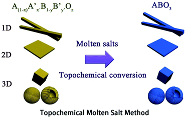 |
| | Fig. 1 The schematic illustration of the topochemical molten salt method. | |
The equilibrium is set up for the TMSS method by the following reaction:
| |  | (1) |
where the value of
x,
x′,
y and
y′ are all greater than or equal to 0 and less than or equal to 1, and
z is a positive integer.
The performance of perovskite compounds in target applications is dramatically affected by the structure and morphology of the material. It is known that the shape of crystalline particles depends on their internal structure, which means that materials with a cubic structure will normally form isotropic particles.23 Regular-perovskite structured materials typically grow as equiaxed particles so it is difficult to synthesize anisotropic particles using conventional methods. The TMSS method is one of the strategic approaches aimed at controllable synthesis, which is associated with using localized solid-state raw materials. This type of topochemical method based on molten salt synthesis has been carried out to prepare various perovskite compounds with one dimension (1D), two dimensions (2D), and three dimensions (3D), such as, rodlike KNbO3/(Na,K)NbO3 using a Nb2O5 template, PbTiO3 using TiO2,36 platelike NaNbO3/KNbO3 using Bi2.5Na3.5Nb5O18,44,49,61 BaTiO3 using BaBi4Ti4O15,38 KNbO3 using K4Nb6O17, (Na,K)NbO3 using K4Nb6O17,51,55 and hollow sphere KNbO3 using Nb2O5.57 More details can be found in Table 1. Meanwhile, it is important to select the right molten salt system. It can be seen in Table 1, that the typical molten salts are metal halides and oxygenated chemicals. The reaction temperature should be higher than the melting point of the molten salts. To achieve a lower melting point, mixtures of two or more salts are usually used which provides a wider operating temperature range. It has to be pointed out that in some reactions, the molten salts not only play a role as the flux, but also join the reaction through the presence of certain cations or anions, such that Zn2+ from ZnCl2 can also be precipitated in the products and ZnEu2Ti3O10 was easily prepared by ion-exchanging K2Eu2Ti3O10 in molten ZnCl2 (melt point = 283 °C) at 300 °C.60 The equilibrium of it might be the following reaction:
| |  | (2) |
Table 1 A summary of different dimensional perovskites synthesized by the TMSS method and their templates
| Dimensionality |
Materials |
Template |
Molten salts |
Reference |
| 1D |
NaNbO3 |
K2Nb8O21 nanowires |
NaCl |
24
|
| Nb2O5 nanorods |
NaCl |
25
|
| KNbO3 |
Nb2O5 nanorods |
KCl |
25
|
| LiNbO3 |
Nb2O5 nanowires |
LiCl |
26
|
| (K,Na)NbO3 |
Nb2O5 nanorods |
KCl |
25 and 27–30
|
| BaTiO3 |
TiO2 nanorods |
NaCl–KCl (1![[thin space (1/6-em)]](https://www.rsc.org/images/entities/char_2009.gif) : :![[thin space (1/6-em)]](https://www.rsc.org/images/entities/char_2009.gif) 1 mol) 1 mol) |
31
|
| H2Ti3O7 nanowires |
Ba(OH)2 |
32–35
|
| PbTiO3 |
TiO2 rods |
NaCl–KCl (1![[thin space (1/6-em)]](https://www.rsc.org/images/entities/char_2009.gif) : :![[thin space (1/6-em)]](https://www.rsc.org/images/entities/char_2009.gif) 1 mol) 1 mol) |
36 and 37
|
| 2D |
BaTiO3 |
BaBi4Ti4O15 platelets |
NaCl–KCl (1![[thin space (1/6-em)]](https://www.rsc.org/images/entities/char_2009.gif) : :![[thin space (1/6-em)]](https://www.rsc.org/images/entities/char_2009.gif) 1 mol) 1 mol) |
38
|
| SrTiO3 |
SrBi4Ti4O15 platelets |
KCl |
39
|
| CaTiO3 |
CaBi4Ti4O15 platelets |
KCl |
40
|
| Ba1−xCaxTiO3 |
Bi4Ti3O12 platelets |
NaCl–KCl (1![[thin space (1/6-em)]](https://www.rsc.org/images/entities/char_2009.gif) : :![[thin space (1/6-em)]](https://www.rsc.org/images/entities/char_2009.gif) 1 mol) 1 mol) |
41
|
| Na0.5Bi0.5TiO3 |
Na0.5Bi4.5Ti4O15 platelets |
NaCl–KCl (1![[thin space (1/6-em)]](https://www.rsc.org/images/entities/char_2009.gif) : :![[thin space (1/6-em)]](https://www.rsc.org/images/entities/char_2009.gif) 1 mol) 1 mol) |
42 and 43
|
| NaNbO3 |
Bi2.5Na3.5Nb5O18 platelets |
NaCl |
44–47
|
| Na3.5Bi2.5Nb5O18 platelets |
NaCl |
7, 44 and 48
|
| KNbO3 |
K4Nb6O17 platelets |
KCl |
49 and 50
|
| Nb2O5 platelets |
KCl |
51
|
| (Na0.5K0.5)NbO3 |
K4Nb6O17 platelets |
KCl |
17
|
| AgSbO3 |
NaSbO3 nanoplates |
AgNO3 |
52
|
| Ag2[Ca1.5M3O10] (M = Nb, Ta) |
Li2[Ca1.5M3O10] (M = Nb, Ta) |
AgNO3 |
53
|
| AgLaNb2O7 |
RbLaNb2O7 |
AgNO3 |
8 and 54
|
| AgA2Nb3O10 (A = Ca, Sr) |
RbA2Nb3O10 (A = Ca, Sr) |
AgNO3 |
46 and 55
|
| PbTiO3 |
PbBi4Ti4O15 |
KCl |
7
|
| 0.4(Na1/2Bi1/2)TiO3–0.6PbTiO3 |
PbBi4Ti4O15 |
NaCl |
56
|
| 3D |
KNbO3 |
Nb2O5 hollow nanospheres |
KCl |
57 and 58
|
| LaMnO3 |
Porous spherical Mn2O3 |
NaNO3–KNO3 (2![[thin space (1/6-em)]](https://www.rsc.org/images/entities/char_2009.gif) : :![[thin space (1/6-em)]](https://www.rsc.org/images/entities/char_2009.gif) 1 mol) 1 mol) |
59
|
| ZnEu2Ti3O10 |
K2Eu2Ti3O10 |
ZnCl2 |
60
|
| AEu2Ti2NbO10 (A = Na, Li) |
CsEu2Ti2NbO10 |
Alkali nitrates |
60
|
2.2 One dimensional morphology
Nanorods, nanowires, nanotubes and other one dimensional materials have recently been investigated with increasing intensity as a result of their novel properties,62 which open up new paths for applications in several fields such as electronics, sensing, catalysis, energy harvesting and information storage. A number of articles on 1D nanostructures have been published,8,26 providing an outline of the research directions for the synthesis and applications of the 1D nanostructures. For example, subwavelength optical microscopy employing a tunable nanometric light source based on KNbO3 nanowires was developed by Yang and co-workers.47 Despite the attractive applications of niobates, there are only a few reports on the synthesis of niobate 1D nanostructures by employing the hydrothermal approach.47,63 Wang et al. have used the TMSS approach for the synthesis of single-crystal sodium and calcium niobate nanorods (Fig. 2).24 The synthesis of sodium and calcium niobate nanorods is a two-step process. First, K2Nb8O21 nanowires were prepared by calcination of Nb2O5 powders in molten KCl at 1000 °C for 3 h. Then, the mixture of the K2Nb8O21 nanowires and NaCl was heated in a tube furnace at 825 or 800 °C for 3 h and 1D sodium and calcium niobates were obtained based on this topochemical molten salt reaction between the K2Nb8O21 nanowires and the molten NaCl salt. The synthesized sodium niobate nanorods, with the same diameter of a few hundred nanowires as that of the precursor, and lengths of several micrometers, show a bundlelike morphology, which is characteristic of the starting K2Nb8O21 nanowires template. The phase of the obtained sodium niobate was determined to be orthorhombic NaNbO3 (JCPDS 33-1270), with lattice parameters of a = 0.5569, b = 1.5123, and c = 0.5505 nm.
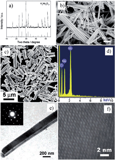 |
| | Fig. 2 (a) XRD and (b) SEM images of the potassium niobate nanowires. The angles for the standard sample of potassium niobate are shown in the lower part of panel a. (c) SEM image of sodium niobate nanorods. (d) EDX spectrum showing the complete conversion from K niobate to Na niobate. (e) TEM image of an individual sodium niobate nanorod. Inset is the corresponding SAED pattern. (f) High-resolution TEM image of the same nanorod shown in panel e (ref. 32 Copyright 2007, American Chemical Society). | |
2.3 Two dimensional morphology
Two dimensional materials are materials in which the electron only has free movement in two dimensions, such as thin films, super lattices and quantum wells. The discovery of graphene largely promoted the development of 2D materials, and many researchers focus on the 2D materials used in solar cells, piezoelectric materials, etc.64 Recently, many efforts have been made to synthesize low dimensional perovskites, through techniques such as hydrothermal and molten salt synthesis (MSS), but the platelet perovskite particles are still not easily obtained due to the nature of regular-perovskite structured materials which typically grow as equiaxed particles. The TMSS method gives a route to obtain the 2D perovskites.44,65 For example, Saito et al. used the TMSS method to obtain plate-like NaNbO3 particles as templates for 〈001〉 oriented (K,Na)NbO3-based ceramics (Fig. 3). Firstly, a Bi2.5Na3.5Nb5O18 (BiNN5) platelet was synthesized at 1100 °C using molten NaCl salt as a flux. Then, using a TMSS reaction, a NaNbO3 platelet was synthesized from the BiNN5 and a complementary reactant, Na2CO3, in a NaCl flux at 950 °C. The by-product, Bi2O3, was removed. The synthesized NaNbO3 had the same morphology as BiNN5, a 0.5 mm thickness and 10–15 mm side length in a developed area, and consisted of a single-phase with the 001 plane of perovskite, identified by JCPDS powder diffraction file card no. 33-1270.44 The formation of the platelet NaNbO3 might be as follows:| |  | (3) |
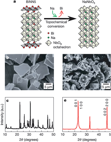 |
| | Fig. 3 Schematic diagram of topochemical conversion from the bismuth layered structure BiNN5 particles to plate-like NaNbO3 particles. (a) Crystal structures of the plate-like BiNN5 and NaNbO3 particles. (b and c) An SEM image and the X-ray diffraction profile of the plate-like BiNN5 particles used as the precursor. (d and e) An SEM image and the X-ray diffraction profile of the plate-like NaNbO3 particles. The X-ray diffraction profile of the NaNbO3 particles is characterized by pseudo-tetragonal Miller indices. The BiNN5 particles are completely converted into the regular perovskite-structured NaNbO3 particles with a preserved plate-like shape (ref. 25 Copyright 2004 Nature Publishing Group.). | |
2.4 Three dimensional morphology
Materials with three dimensional morphologies, including composites consisting of one or more basic structural units in zero dimensional, one-dimensional, two-dimensional or porous materials, such as hollow spheres,50 nickel foam66etc., have aroused much attention in the academic community and industry due to their unique microstructures and singular properties. The TMSS method has been used to obtain perovskites with 3D morphologies, for example, porous spherical and cubic LaMnO3 from porous Mn2O3 precursors in a mixture of NaNO3 and KNO3.59 There is another example, in which Xing et al. obtained KNbO3 hollow spheres from Nb2O5 hollow spheres via the TMSS method (Fig. 4).57 In the KCl molten salt, K+ needed to diffuse inside the T-Nb2O5 hollow spheres, and this process involved bond-breaking, rebonding, and the generation of new bonds. Viewed along the c axis of Nb2O5, the NbO6 and NbO7 units were corner-sharing, and in the perovskite KNbO3 crystal, the NbO6 octahedron units connected with shared corners along the a, b, and c axes. Therefore, although the small rods of the shell became cubelike, due to the high thermal stability of the Nb2O5 hollow nanospheres and the compatability of the structure of the Nb2O5 and KNbO3, the morphology of the hollow spheres could be kept and KNbO3 hollow nanospheres were obtained.
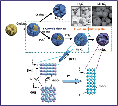 |
| | Fig. 4 Formation processes and structure evolution of the KNbO3 hollow spheres and Nb2O5 solid spheres. The insets are the Nb2O5 hollow spheres and the KNbO3 hollow spheres (ref. 31 Copyright 2013, the Royal Society of Chemistry). | |
3 Various functional perovskites synthesized by TMSS
The ABO3 family with perovskite structure has aroused a broad interest since it was investigated in the 1970s.67 They have important applications in fields such as piezoelectrics, photocatalysis, ferroelectrics, multiferroics, and negative thermal expansion materials (NTE).68 The synthesis of these functional perovskites in the form of nano/micro crystalline powders and defined nanoscale architectures has been realized in different TMSS systems. Depending on the nature of the TMSS, low temperatures, short times, tunable morphologies, controllable stoichiometric ratios, and a broad range of inorganic crystalline structures of functional perovskites can be achieved.
3.1 Piezoelectric perovskites synthesized by TMSS
Piezoelectric materials can produce an electric field upon mechanical deformation, and form mechanical deformation via the effect of the electric field.24,44,69 The inherent mechanical electric coupling effect means piezoelectric materials have been widely used in nanometer generators,70 flexible nanocomposite generators (Fig. 5),71,72 sensors,68 actuators,73 and other electronic devices.74,75 Due to their significant piezoelectric properties the perovskite-type piezoelectric materials such as, Pb(Zr,Ti)O3 (PZT),76,77 Bi0.5Na0.5TiO3 (BNT),69,78 (K,Na)NbO3 (KNN),44,72 and BaTiO3 (BT)72 based materials, arouse widespread interest. The piezoelectric properties are largely affected by the morphology and structure of the materials (Fig. 5a–e),45,71 and the piezoelectric properties and morphology of the compounds can be tailored by the TMSS method. For example, the NaNbO3 platelet, synthesized by the TMSS method, is used as a reactive template for textured (K,Na)NbO3–LiTaO3(–LiSbO3) polycrystals synthesized by the reactive-templated grain growth (RTGG) method which exhibit a high piezoelectric constant d33 of 416 pC N−1.44 Rod-like ANbO3 (A = K, Na, (Na,K)) were fabricated by a TMSS method, shown in Fig. 6.25 The process is as follow: first, the precursor KNb3O8 with a rod structure was prepared under the conditions of a KCl molten salt environment at 800 °C for 3 h. Then, rod-like H3ONb3O8 and Nb2O5 were obtained from the rod-like KNb3O8 precursor. Finally, the rod-like ANbO3 (A = K, Na, (Na,K)) were achieved via the intermediate oxide Nb2O5. The rod-like structure of the final product can only be achieved when using the rod-like Nb2O5 precursor. The structural evolution investigated among protonic niobate, niobium oxide, and niobates, shows that the similar structure (three NbO6 octahedra connected with shared corners and edges along the [001] direction) is the key to maintaining the morphology of the precursor. The (Na,K)NbO3 ceramic sintered from the as-prepared rodlike particles under pressureless conditions in air performed with a high piezoelectricity (d33 = 140 pC N−1), which is much better than that of the ceramics obtained from cubic or spherical particles (d33 = 97 pC N−1).25
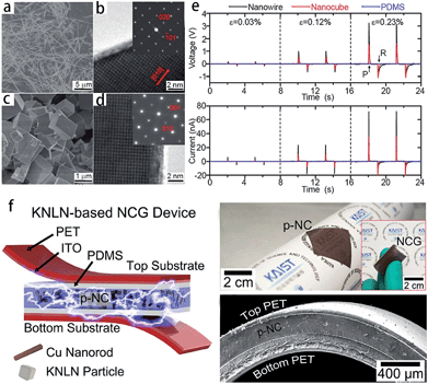 |
| | Fig. 5 SEM and TEM images of NaNbO3 nanowires (a and b) and nanocubes (c and d). (e) Power generation of NaNbO3 nanowire-based (black lines) and nanocube-based (red lines) NGs at a given compressive strain. The top image is the open circuit voltage and below is the closed circuit current. PDMS itself (blue lines) does not show any signals. Here, ε, P, and R are for the strain value, press, and release, respectively. (f) Schematic of a flexible nanocomposite generator (NCG) device using 0.942 (K0.480Na0.535)NbO3–0.058LiNbO3 (KNLN) particles and Cu NRs. Photograph of the flexible p-NC layer attached to a rolled paper. The inset shows the final NCG device bent by fingers (ref. 71 Copyright 2014, 2011 American Chemical Society and ref. 72 Copyright 2014, WILEY-VCH Verlag GmbH & Co. KGaA, Weinheim). | |
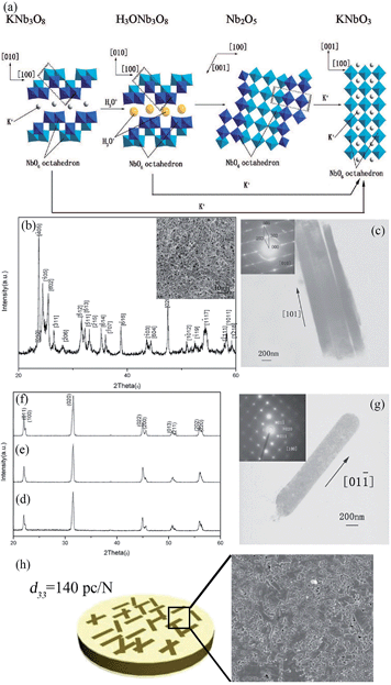 |
| | Fig. 6 (a) Schematic illustration of the structural transformations of the Nb-containing species along with the mechanism of KNbO3 synthesis by TMSS treatment. (b) An XRD pattern of the Nb2O5 particles obtained from the rodlike H3ONb3O8 particles. The inset is an SEM micrograph of the Nb2O5 particles. (c) TEM image of the Nb2O5 rods with (inset) a typical SEAD pattern obtained from the rods. (d–f) XRD patterns of the KNbO3 particles obtained from different precursors KNb3O8, H3ONb3O8 and Nb2O5, respectively. (g) TEM image of an isolated KNbO3 rod obtained from the precursor Nb2O5 particles with (inset) its corresponding SEAD pattern. (h) The piezoelectric constant d33 of the (Na,K)NbO3 ceramic is 140 pC N−1, and the SEM image of the surface of the ceramic (ref. 33 Copyright 2009, American Chemical Society). | |
The reaction of the rod-like KNb3O8 might be as follows: first, the Nb2O5 and KCl were reacted to produce KNb3O8. Then an ion exchange of the K+ ion by the hydronium ion was observed according to the reaction:
| |  | (4) |
Afterward, the H3ONb3O8 was heated to remove H2O, which is depicted as follows:
| | | H3ONb3O8 → HNb3O8 + H2O | (5) |
| |  | (6) |
The reaction for the formation of the KNbO3 rods from the rodlike Nb2O5 particles is as follows:
| | | Nb2O5 + K2CO3 → Nb2O5 + K2O + CO2 → 2KNbO3 + CO2 | (7) |
3.2 Photocatalysis perovskites synthesized by TMSS
Current synthetic challenges for the crystal growth of complex oxides can be addressed by utilizing TMSS methods, which have made a significant impact in research involving solar energy conversion.30,52,79 The improved phase-purity and particle homogeneity is in favour of enhancing photocatalytic properties. Early investigations into the photocatalytic activities of metal oxides utilized only high-temperature ‘grind and heat’ solid state syntheses to obtain the desired products.80 Starting with the research of the Maggard group, the MSS of metal-oxide photocatalysts has been used increasingly to understand the impact of the particle sizes, morphologies, and the surface.81,82 The TMSS preparation of perovskites has been of increasing importance in a growing number of studies probing photocatalytic mechanisms and the surface reactivities of photocatalysts, such as AgSbO3,52 LaMnO3,59 KNbO3 (ref. 57) and AgTaO3, AFeO3 (A = Bi, La, Ln), and Bi(Mg3/8Fe2/8Ti3/8)O3.83 For example, AgSbO3 visible-light photocatalysts were synthesized from NaSbO3 nanoplates, which were prepared by salt-assisted aerosol combustion, via the TMSS method (Fig. 7).52 It was revealed that the surface chemistry and particle morphology influenced the photocatalytic activity. Visible-light-induced photodegradation of RhB was selected as the model reaction to evaluate the photocatalytic properties of the different AgSbO3 samples. AgSbO3 prepared via the TMSS route exhibited a greater photoactivity for the photodegradation of RhB in comparison to the AgSbO3 synthesized from the other method (Fig. 7e). It can be predicted that further modifications of the TMSS methods for tuning particle sizes, morphologies, and specific surface areas could be used to obtain other nano perovskites with highly desired optical and photocatalytic properties in future.
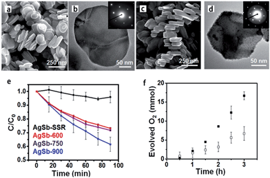 |
| | Fig. 7 (a) SEM and (b) TEM images of the NaSbO3 product obtained from an aerosol-assisted synthesis. (c) SEM and (d) TEM images of the AgSbO3, single-crystalline NaSbO3 plates in molten AgNO3 were used as the template. (e) Rhodamine B photocatalytic degradation under λ = 400–500 nm illumination. (f) Oxygen evolution in the presence of 0.1 M AgNO3 (ref. 55 Copyright 2015, American Chemical Society). | |
3.3 Negative thermal expansion (NTE) perovskites synthesized by TMSS
The thermal expansion compatibility of different components is one of the key problems for modern devices, such as thin films, multilayer chip capacitors (MLCCs), solid oxide fuel cells, thermoelectric materials, and high temperature piezoelectrics. Thermal stress could give rise to device failure due to an undesirable mismatch of the coefficients of thermal expansion (CTE). The design of highly reliable devices should pay enough attention to the control of thermal expansion, which is extremely difficult, but an important topic. The size effect brings about unexpected phenomena upon thermal expansion. With decreasing particle sizes, NTE can be produced in those compounds which have normal thermal expansion in the bulk state, such as magnetic nanoparticles.84 Moreover, giant NTE of ferroelectrics is lost and transformed to a positive thermal expansion, as particle size decreases. The development of TMSS can reveal the nature of NTE perovskites as the particle size, stoichiometric ratio and dispersity can be controlled via this chemical method. Perovskite type NTE materials were synthesized by the TMSS method, for example PbTiO3 (ref. 36) and PbTiO3-based materials.56 It should be mentioned that the effect of size on thermal expansion is just beginning to be studied. More interesting results will appear, and the research in this field is significant for the development of devices, as the nano/micro materials for devices become important.84
3.4 Other functional perovskites synthesized by TMSS
Other functional perovskites, such as multiferroic materials, catalysts etc. are also prepared via the TMSS method. For perovskite-type multiferroic materials, they have potential applications for new types of electronic devices, such as ferroelectrics, multiple-state memories and new data-storage media.85–87 The synthesis method used to obtain the desired nanostructures is crucial for exploiting nanoscale electric, magnetic, and thermal properties. For example, for the multiferroic BiFeO3-based material, the limited available information relating to the size dependence of the physical properties is mainly due to the difficulty in preparing the pure BiFeO3-based material.88 During the synthesis of BiFeO3, the kinetics of the phase formation in the Bi2O3–Fe2O3 system can easily lead to the appearance of impurity phases, such as Bi25FeO40 and Bi2Fe4O9. The TMSS is an appropriate and rapid method for such materials. Not only high purity samples, but also samples with controllably sized particles can be obtained.86,89 Perovskite-type catalysts, are promising automotive exhaust catalysts90 for the catalytic removal of VOCs59etc. due to their surface redox properties, high bulk oxygen mobility and good thermal stability. The morphology and surface area have a great impact on the performance of catalysts. For example, the porous spherical and cubic LaMnO3 with a high activity for the catalytic removal of toluene was produced in a morphologically controlled synthesis via the TMSS method from the porous spherical M2O3.59
4 Double and layered perovskites synthesized by TMSS
Double perovskite oxides with the general formula AA0BB0O6 (where A and A0 are rare earth or alkaline earth metals, and B and B0 are d-block transition metals) display a wide variety of interesting physical properties that vary with changes in their composition. Considerable research is being carried out to explore new double perovskite materials, to understand the origin of their properties (e.g. magnetodielectric, magnetoresistance, and magneto-capacitance), to improve their properties, and to adapt the materials to produce technology for each application. The nanostructure of double perovskites can significantly enhance their properties. To obtain nanostructures, such as, La2CoMnO6, La2NiMnO6, Ca2Fe0.8Co0.2MoO6, the TMSS method has been applied due to the tunable morphology and the controllable stoichiometric ratio.89,91,92
Members of the Dion–Jacobson family of layered perovskites,93–95 A[A′n−1BnO3n+1] (A = alkali, A′ = alkaline earth or rare earth, B = transition metal), have an equal number of A(A′) and B cations, so they are ideal precursors to nondefective, three dimensional (3D) perovskites of the general formula AA′n−1BnO3n.60 For example, ZnEu2Ti3O10 was prepared by ion-exchanging K2Eu2Ti3O10 in molten ZnCl2. AEu2Ti2NbO10 (A = Na, Li) compounds were prepared from CsEu2Ti2NbO10 in the molten alkali nitrates. The conversion of a Dion–Jacobson layered perovskite A[A′n−1BnO3n+1] to a 3D perovskite AA′n−1BnO3n requires that either the A, A′, or B ion be reducible.60 Furthermore, it is well known that the photocatalytic efficiency of a given semiconductor photocatalyst depends on three physical processes, including the light absorption, the transport of the charge carriers and the recombination of the photogenerated electron–hole pairs. The electronic band structure plays a critical role in the above processes. Furthermore, it was found that the electronic band structure of layered perovskites is able to be engineered.96 Boltersdorf et al. systematically reported that Ag2La2Ti3O10, and AgLaNb2O7, AgA2Nb3O10 (A = Ca, Sr) were prepared by the TMSS method using solid-state prepared Rb2La2Ti3O10 in AgNO3 salts (Fig. 8), and it was found that the silver-exchanged RbA2Nb3O10 layered structures exhibited the highest photocatalytic hydrogen formation rates under ultraviolet and visible irradiation (∼13![[thin space (1/6-em)]](https://www.rsc.org/images/entities/char_2009.gif) 616 μmol H2 g−1 h−1).55
616 μmol H2 g−1 h−1).55
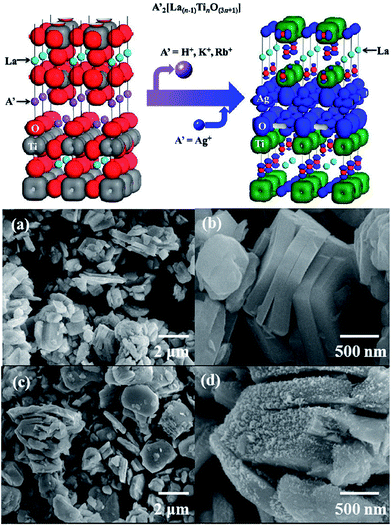 |
| | Fig. 8 (Top) Electron density plot of A′2[La(n−1)TinO(3n+1)] and Ag2La2Ti3O10. (a and b) FESEM images of solid-state prepared Rb2La2Ti3O10. (c and d) Silver-exchanged Ag2La2Ti3O10 in AgNO3 flux (ref. 30 Copyright 2013, American Chemical Society). | |
5 Conclusions and outlook
Synthesizing materials with the desired morphology and phase purity in a reproducible and environmentally friendly manner is arousing considerable attention in materials science all over the world. After two decades of studies on the topic of TMSS, there has been great progress in aspects of new TMSS processes for different perovskites. The new interdisciplinary field of TMSS for perovskites has been reviewed. The mechanism of the TMSS method is also presented. The properties, such as, piezoelectric, photocatalytic, negative thermal expansion etc., and the different morphologies of perovskite compounds could be tailored by the TMSS method. Meanwhile, the double and layered perovskites can also be obtained by TMSS methods with a tunable morphology and a controllable stoichiometric ratio.
For future applications of TMSS in perovskites, there still exist some problems which have to be considered. For example, the solubility of different precursors and the understanding of the growth mechanisms of perovskites are still not fully developed; improved understanding of the chemical and physical properties and the crystal structures of the materials is called for. Further study of the TMSS method for tuning particle morphologies, size and crystallinity can be used to obtain other target morphologies of perovskites that are doped or have highly desirable piezoelectric, photocatalytic, negative thermal expansion properties etc. In addition, not limited to the preparation of perovskites, the TMSS method can be extended to obtain other kinds of functional materials, for example, a high voltage layered Li1.2Ni0.16Co0.08Mn0.56O2 cathode material with a hollow spherical structure has been synthesized by the TMSS method in a NaCl flux from MnO2 hollow spheres.97 The development of lower melting temperature molten salts (ionic liquids) for the TMSS method is anticipated to guide us to new synthetic protocols.
Acknowledgements
The authors gratefully acknowledge financial support from National Natural Science Foundation of China (Grant No. 21231001, 20921001, 21301180 and 21131004) and the 973 Program (2013CB933004), and the “Strategic Priority Research Program” of the Chinese Academy of Sciences (grant number XDA09020000).
Notes and references
- X. Liu, N. Fechler and M. Antonietti, Chem. Soc. Rev., 2013, 42, 8237–8265 RSC.
- W. Xiao and D. Wang, Chem. Soc. Rev., 2014, 43, 3215–3228 RSC.
- N. V. Plechkova and K. R. Seddon, Chem. Soc. Rev., 2008, 37, 123–150 RSC.
- R. E. Schaak and T. E. Mallouk, Chem. Mater., 2002, 14, 1455–1471 CrossRef CAS.
- Y. Maeno, H. Hashimoto, K. Yoshida, S. Nishizaki, T. Fujita, J. G. Bednorz and F. Lichtenberg, Nature, 1994, 372, 532–534 CrossRef CAS.
- Z. Pan, Q. Wang, J. Chen, C. Liu, L. Fan, L. Liu, L. Fang and X. Xing, J. Am. Ceram. Soc., 2015, 98, 104–108 CrossRef CAS.
- S. F. Poterala, Y. Chang, T. Clark, R. J. Meyer and G. L. Messing, Chem. Mater., 2010, 22, 2061–2068 CrossRef CAS.
- Y. Xia, P. Yang, Y. Sun, Y. Wu, B. Mayers, B. Gates, Y. Yin, F. Kim and H. Yan, Adv. Mater., 2003, 15, 353–389 CrossRef CAS.
- M. G. Kanatzidis, R. Pöttgen and W. Jeitschko, Angew. Chem., Int. Ed., 2005, 44, 6996–7023 CrossRef CAS PubMed.
- X. An, Y. Wang, J. Deng, J. Chen and X. Xing, Mater. Res. Bull., 2014, 51, 74–79 CrossRef CAS.
- X. An, Y. Wang, J. Deng, J. Chen, R. Yu and X. Xing, Inorg. Chem. Commun., 2014, 44, 79–82 CrossRef CAS.
- Z. Cai, X. Xing, R. Yu, G. Liu and Q. Xing, J. Alloys Compd., 2006, 420, 273–277 CrossRef CAS.
- J. Chen, C. Zhang and X. Xing, Mater. Lett., 2008, 62, 2332–2334 CrossRef CAS.
- J. Deng, J. Chen, R. Yu, G. Liu and X. Xing, Int. J. Mater. Res., 2009, 100, 1552–1556 CrossRef CAS.
- J. X. Deng, L. H. Li, J. Chen, R. B. Yu and X. R. Xing, Inorg. Chem. Commun., 2012, 21, 92–95 CrossRef CAS.
- L. Hu, J. Chen, L. Fan, J. Deng, R. Yu and X. Xing, J. Am. Ceram. Soc., 2014, 97, 1009–1011 CrossRef CAS.
- L. H. Li, J. Chen, J. X. Deng, R. B. Yu, L. J. Qiao, G. R. Liu and X. R. Xing, Eur. J. Inorg. Chem., 2008, 2186–2190 CrossRef CAS.
- L. H. Li, J. X. Deng, J. Chen, R. B. Yu, L. J. Qiao and X. R. Xing, J. Alloys Compd., 2009, 471, 428–431 CrossRef CAS.
- L. H. Li, X. R. Xing, J. Chen, Z. Y. Cai, J. X. Deng, C. Sun and G. R. Liu, Chin. J. Inorg. Chem., 2006, 22, 1491–1494 CAS.
- X. Xing, S. Dai, Z. Zhu and T. Tanaka, Thermochim. Acta, 2002, 383, 31–35 CrossRef CAS.
- X. Xing, C. Zhang, L. Qiao, G. Liu and J. Meng, J. Am. Ceram. Soc., 2006, 89, 1150–1152 CrossRef CAS.
- X. Xing, Z. Zhu, S. Dai and T. Tanaka, Thermochim. Acta, 2001, 372, 109–112 CrossRef CAS.
- I. Pribošič, D. Makovec and M. Drofenik, Chem. Mater., 2005, 17, 2953–2958 CrossRef.
- C.-Y. Xu, L. Zhen, R. Yang and Z. L. Wang, J. Am. Chem. Soc., 2007, 129, 15444–15445 CrossRef CAS PubMed.
- L. H. Li, J. X. Deng, J. Chen, X. Y. Sun, R. B. Yu, G. R. Liu and X. R. Xing, Chem. Mater., 2009, 21, 1207–1213 CrossRef CAS.
- A. C. Santulli, H. Zhou, S. Berweger, M. B. Raschke, E. Sutter and S. S. Wong, CrystEngComm, 2010, 12, 2675–2678 RSC.
- L.-Q. Cheng, K. Wang and J.-F. Li, Chem. Commun., 2013, 49, 4003–4005 RSC.
- L.-Q. Cheng, K. Wang, Q. Yu and J.-F. Li, J. Phys. Chem. C, 2014, 2, 1519–1524 CAS.
- L.-Q. Cheng, K. Wang, J.-F. Li, Y. Liu and J. Li, J. Phys. Chem. C, 2014, 2, 9091–9098 CAS.
- J. Boltersdorf, N. King and P. A. Maggard, CrystEngComm, 2015, 17, 2225–2241 RSC.
- K.-C. Huang, T.-C. Huang and W.-F. Hsieh, Inorg. Chem., 2009, 48, 9180–9184 CrossRef CAS PubMed.
- D. K. Lee, I.-S. Cho, S. Lee, D. H. Kim, H.-W. Shim, D.-W. Kim and K. S. Hong, Eur. J. Inorg. Chem., 2010, 1343–1347 CrossRef CAS.
- J. Dupont, R. F. de Souza and P. A. Z. Suarez, Chem. Rev., 2002, 102, 3667–3692 CrossRef CAS PubMed.
- R. E. Cohen, Nature, 1992, 358, 136–138 CrossRef CAS.
- S.-W. Cheong and M. Mostovoy, Nat. Mater., 2007, 6, 13–20 CrossRef CAS PubMed.
- Z. Cai, X. Xing, R. Yu, X. Sun and G. Liu, Inorg. Chem., 2007, 46, 7423–7427 CrossRef CAS PubMed.
- M. M. Lee, J. Teuscher, T. Miyasaka, T. N. Murakami and H. J. Snaith, Science, 2012, 338, 643–647 CrossRef CAS PubMed.
- D. Liu, Y. Yan and H. Zhou, J. Am. Ceram. Soc., 2007, 90, 1323–1326 CrossRef CAS.
- Y. Saito and H. Takao, Jpn. J. Appl. Phys., 2006, 45, 7377–7381 CrossRef CAS.
- Y. Saito, H. Takao and K. Wada, Ceram. Int., 2008, 34, 745–751 CrossRef CAS.
- X. Yan, F. Gao and Z. Liu, Ceram. Int., 2014, 40, 4927–4932 CrossRef CAS.
- W. Zhao, H. Zhou, Y. Yan and D. Liu, J. Am. Ceram. Soc., 2008, 91, 1322–1325 CrossRef CAS.
- A. Hussain, J. U. Rahman, F. Ahmed, J.-S. Kim, M.-H. Kim, T.-K. Song and W.-J. Kim, J. Eur. Ceram. Soc., 2015, 35, 919–925 CrossRef CAS.
- Y. Saito, H. Takao, T. Tani, T. Nonoyama, K. Takatori, T. Homma, T. Nagaya and M. Nakamura, Nature, 2004, 432, 84–87 CrossRef CAS PubMed.
- W. Zeng, X.-M. Tao, S. Chen, S. Shang, H. L. W. Chan and S. H. Choy, Energy Environ. Sci., 2013, 6, 2631–2638 CAS.
- Y. Yan, D. Liu, W. Zhao, H. Zhou and H. Fang, J. Am. Ceram. Soc., 2007, 90, 2399–2403 CrossRef CAS.
- Y. Nakayama, P. J. Pauzauskie, A. Radenovic, R. M. Onorato, R. J. Saykally, J. Liphardt and P. Yang, Nature, 2007, 447, 1098–1101 CrossRef CAS PubMed.
- Z. L. Wang and J. H. Song, Science, 2006, 312, 242–246 CrossRef CAS PubMed.
- Y. Saito and H. Takao, J. Eur. Ceram. Soc., 2007, 27, 4085–4092 CrossRef CAS.
- F. Caruso, R. A. Caruso and H. Möhwald, Science, 1998, 282, 1111–1114 CrossRef CAS PubMed.
- L. H. Li, J. X. Deng, R. B. Yu, J. Chen, X. W. Wang and X. R. Xing, Inorg. Chem., 2010, 49, 1397–1403 CrossRef CAS PubMed.
- D. P. Chen, W. Bowers and S. E. Skrabalak, Chem. Mater., 2015, 27, 174–180 CrossRef CAS.
- N. S. P. Bhuvanesh and P. M. Woodward, J. Am. Chem. Soc., 2002, 124, 14294–14295 CrossRef CAS PubMed.
- D. Arney and P. A. Maggard, ACS Catal., 2012, 2, 1711–1717 CrossRef CAS.
- J. Boltersdorf and P. A. Maggard, ACS Catal., 2013, 3, 2547–2555 CrossRef CAS.
- S. F. Poterala, J. R. J. Meyer and G. L. Messing, J. Am. Ceram. Soc., 2011, 94, 2323–2329 CrossRef CAS.
- L. H. Li, J. X. Deng, R. B. Yu, J. Chen, Z. Wang and X. R. Xing, J. Mater. Chem. A, 2013, 1, 11894–11900 CAS.
- P. X. Gao, J. Song, J. Liu and Z. L. Wang, Adv. Mater., 2007, 19, 67–72 CrossRef CAS.
- Y. Wang, S. Xie, J. Deng, S. Deng, H. Wang, H. Yan and H. Dai, ACS Appl. Mater. Interfaces, 2014, 6, 17394–17401 CAS.
- R. E. Schaak and T. E. Mallouk, J. Am. Chem. Soc., 2000, 122, 2798–2803 CrossRef CAS.
- T. Gao, J. Liao, J. Wang, Y. Qiu, Q. Yang, M. Zhang, Y. Zhao, L. Qin, H. Xue, Z. Xiong, L. Chen and Q.-M. Wang, J. Phys. Chem. A, 2015, 3, 9965–9971 CAS.
- M.-A. Einarsrud and T. Grande, Chem. Soc. Rev., 2014, 43, 2187–2199 RSC.
- A. Magrez, E. Vasco, J. W. Seo, C. Dieker, N. Setter and L. Forró, J. Phys. Chem. B, 2006, 110, 58–61 CrossRef CAS PubMed.
- J. N. Coleman, M. Lotya, A. O'Neill, S. D. Bergin, P. J. King, U. Khan, K. Young, A. Gaucher, S. De, R. J. Smith, I. V. Shvets, S. K. Arora, G. Stanton, H.-Y. Kim, K. Lee, G. T. Kim, G. S. Duesberg, T. Hallam, J. J. Boland, J. J. Wang, J. F. Donegan, J. C. Grunlan, G. Moriarty, A. Shmeliov, R. J. Nicholls, J. M. Perkins, E. M. Grieveson, K. Theuwissen, D. W. McComb, P. D. Nellist and V. Nicolosi, Science, 2011, 331, 568–571 CrossRef CAS PubMed.
- D. Lv, R. Zuo and S. Su, J. Am. Ceram. Soc., 2012, 95, 1838–1842 CrossRef CAS.
- T. A. Schaedler, A. J. Jacobsen, A. Torrents, A. E. Sorensen, J. Lian, J. R. Greer, L. Valdevit and W. B. Carter, Science, 2011, 334, 962–965 CrossRef CAS PubMed.
- W. F. Libby, Science, 1971, 171, 499–500 CAS.
- J. Zhu, H. Li, L. Zhong, P. Xiao, X. Xu, X. Yang, Z. Zhao and J. Li, ACS Catal., 2014, 4, 2917–2940 CrossRef CAS.
- J. Zhang, Z. Pan, F.-F. Guo, W.-C. Liu, H. Ning, Y. B. Chen, M.-H. Lu, B. Yang, J. Chen, S.-T. Zhang, X. Xing, J. Rödel, W. Cao and Y.-F. Chen, Nat. Commun., 2015, 6, 6615 CrossRef CAS PubMed.
- Z. L. Wang and J. Song, Science, 2006, 312, 242–246 CrossRef CAS PubMed.
- J. H. Jung, M. Lee, J.-I. Hong, Y. Ding, C.-Y. Chen, L.-J. Chou and Z. L. Wang, ACS Nano, 2011, 5, 10041–10046 CrossRef CAS PubMed.
- C. K. Jeong, K.-I. Park, J. Ryu, G.-T. Hwang and K. J. Lee, Adv. Funct. Mater., 2014, 24, 2620–2629 CrossRef CAS.
- P. Muralt, R. G. Polcawich and S. Trolier-McKinstry, MRS Bull., 2009, 34, 658–664 CrossRef CAS.
- W. Wu, X. Wen and Z. L. Wang, Science, 2013, 340, 952–957 CrossRef CAS PubMed.
- W. Wu, L. Wang, Y. Li, F. Zhang, L. Lin, S. Niu, D. Chenet, X. Zhang, Y. Hao, T. F. Heinz, J. Hone and Z. L. Wang, Nature, 2014, 514, 470–474 CrossRef CAS PubMed.
- H. Kang, J. Chen, L. Liu, C. Hu, L. Fang and X. Xing, Inorg. Chem. Commun., 2013, 31, 66–68 CrossRef CAS.
- K.-I. Park, J. H. Son, G.-T. Hwang, C. K. Jeong, J. Ryu, M. Koo, I. Choi, S. H. Lee, M. Byun, Z. L. Wang and K. J. Lee, Adv. Mater., 2014, 26, 2514–2520 CrossRef CAS PubMed.
- S.-T. Zhang, A. B. Kounga, E. Aulbach, H. Ehrenberg and J. Roedel, Appl. Phys. Lett., 2007, 91, 112906 CrossRef.
- X. An, J. Deng, J. Chen and X. Xing, Mater. Res. Bull., 2013, 48, 4984–4988 CrossRef CAS.
- K. Domen, J. Yoshimura, T. Sekine, A. Tanaka and T. Onishi, Catal. Lett., 1990, 4, 339–343 CrossRef CAS.
- D. Arney, B. Porter, B. Greve and P. A. Maggard, J. Photochem. Photobiol., A, 2008, 199, 230–235 CrossRef CAS.
- D. Arney, C. Hardy, B. Greve and P. A. Maggard, J. Photochem. Photobiol., A, 2010, 214, 54–60 CrossRef CAS.
- W. Zhang, J. Chen, X. An, Q. Wang, L. Fan, F. Wang, J. Deng, R. Yu and X. Xing, Dalton Trans., 2014, 43, 9255–9259 RSC.
- J. Chen, L. Hu, J. Deng and X. Xing, Chem. Soc. Rev., 2015, 44, 3522–3567 RSC.
- W. Eerenstein, N. D. Mathur and J. F. Scott, Nature, 2006, 442, 759–765 CrossRef CAS PubMed.
- J. Wang, J. B. Neaton, H. Zheng, V. Nagarajan, S. B. Ogale, B. Liu, D. Viehland, V. Vaithyanathan, D. G. Schlom, U. V. Waghmare, N. A. Spaldin, K. M. Rabe, M. Wuttig and R. Ramesh, Science, 2003, 299, 1719–1722 CrossRef CAS PubMed.
- I. Grinberg, D. V. West, M. Torres, G. Gou, D. M. Stein, L. Wu, G. Chen, E. M. Gallo, A. R. Akbashev, P. K. Davies, J. E. Spanier and A. M. Rappe, Nature, 2013, 503, 509–512 CrossRef CAS PubMed.
- M. Fiebig, T. Lottermoser, D. Frohlich, A. V. Goltsev and R. V. Pisarev, Nature, 2002, 419, 818–820 CrossRef CAS PubMed.
- J. Chen, X. Xing, A. Watson, W. Wang, R. Yu, J. Deng, L. Yan, C. Sun and X. Chen, Chem. Mater., 2007, 19, 3598–3600 CrossRef CAS.
- G. Xu, H. Bai, X. Huang, W. He, L. Li, G. Shen and G. Han, J. Phys. Chem. A, 2015, 3, 547–554 CAS.
- Y. Mao, J. Parsons and J. S. McCloy, Nanoscale, 2013, 5, 4720–4728 RSC.
- J. Chen, R. Yu, L. Li, C. Sun, T. Zhang, H. Chen and X. Xing, Eur. J. Inorg. Chem., 2008, 3655–3660 CAS.
- M. Dion, M. Ganne and M. Tournoux, Mater. Res. Bull., 1981, 16, 1429–1435 CrossRef CAS.
- M. M. J. Treacy, S. B. Rice, A. J. Jacobson and J. T. Lewandowski, Chem. Mater., 1990, 2, 279–286 CrossRef CAS.
- A. J. Jacobson, J. W. Johnson and J. T. Lewandowski, Inorg. Chem., 1985, 24, 3727–3729 CrossRef CAS.
- F. Meng, Z. Hong, J. Arndt, M. Li, M. Zhi, F. Yang and N. Wu, Nano Res., 2012, 5, 213–221 CrossRef CAS.
- X. He, J. Wang, R. Kloepsch, S. Krueger, H. Jia, H. Liu, B. Vortmann and J. Li, Nano Res., 2014, 7, 110–118 CrossRef CAS.
|
| This journal is © The Royal Society of Chemistry 2016 |
Click here to see how this site uses Cookies. View our privacy policy here.  Open Access Article
 ab,
Jinxia
Deng
a,
Jun
Chen
a and
Xianran
Xing
*a


![[thin space (1/6-em)]](https://www.rsc.org/images/entities/char_2009.gif) :
:![[thin space (1/6-em)]](https://www.rsc.org/images/entities/char_2009.gif) 1 mol)
1 mol)![[thin space (1/6-em)]](https://www.rsc.org/images/entities/char_2009.gif) :
:![[thin space (1/6-em)]](https://www.rsc.org/images/entities/char_2009.gif) 1 mol)
1 mol)![[thin space (1/6-em)]](https://www.rsc.org/images/entities/char_2009.gif) :
:![[thin space (1/6-em)]](https://www.rsc.org/images/entities/char_2009.gif) 1 mol)
1 mol)![[thin space (1/6-em)]](https://www.rsc.org/images/entities/char_2009.gif) :
:![[thin space (1/6-em)]](https://www.rsc.org/images/entities/char_2009.gif) 1 mol)
1 mol)![[thin space (1/6-em)]](https://www.rsc.org/images/entities/char_2009.gif) :
:![[thin space (1/6-em)]](https://www.rsc.org/images/entities/char_2009.gif) 1 mol)
1 mol)![[thin space (1/6-em)]](https://www.rsc.org/images/entities/char_2009.gif) :
:![[thin space (1/6-em)]](https://www.rsc.org/images/entities/char_2009.gif) 1 mol)
1 mol)


![[thin space (1/6-em)]](https://www.rsc.org/images/entities/char_2009.gif) 616 μmol H2 g−1 h−1).55
616 μmol H2 g−1 h−1).55


