 Open Access Article
Creative Commons Attribution 3.0 Unported Licence
A binder-free electrode architecture design for lithium–sulfur batteries: a review
Junling
Guo
 b and
Jinping
Liu
 *a
*a
aSchool of Chemistry, Chemical Engineering and Life Science, State Key Laboratory of Advanced Technology for Materials Synthesis and Processing, Wuhan University of Technology, Wuhan 430070, People's Republic of China. E-mail: liujp@whut.edu.cn
bState Center for International Cooperation on Designer Low-carbon & Environmental Materials, Zhengzhou University, 100 Kexue Avenue, Zhengzhou 450001, People's Republic of China
First published on 25th April 2019
Abstract
Lithium–sulfur batteries (LSBs) are considered to be one of the most promising next-generation electrochemical power sources to replace commercial lithium-ion batteries because of their high energy density. However, practical application of LSBs is hindered by two critical drawbacks: “redox shuttle reactions” of dissolved polysulfides at the cathode side and Li dendrites at the Li anode side. Therefore, various approaches have been proposed to break down technical barriers in LSB systems. The overall device performance of LSBs depends on not only the development of host materials but also the superior architecture design of electrodes. Among these architectures, binder-free electrodes are verified to be one of the most effective structural designs for high-performance LSBs. Therefore, it is urgent to review recent advances in binder-free electrodes for promoting the fundamental and technical advancements of LSBs. Herein, recently emergent studies using various binder-free architectures in sulfur cathodes and lithium metal anodes are reviewed. These binder-free electrodes, with well-interconnected structures and abundant structural space, can provide a continuous pathway for fast/uniform electron transport/distribution, load sufficient active materials for ensuring high energy density, and afford large electrochemically active surface areas where electrons and Li ions can come into contact with the active materials for fast conversion reactions, thus leading to suitable applications for LSBs. Subsequently, the advantages and challenges of binder-free architectures are discussed from several recently emergent studies using binder-free structured sulfur cathodes or Li metal anodes. The future prospects of LSBs with binder-free electrode structure designs are also discussed.
1. Introduction
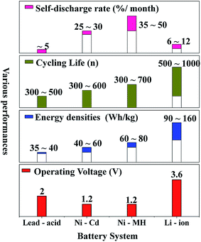
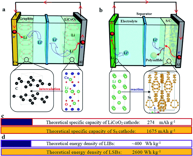
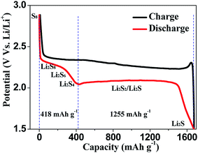
Nowadays, among commercialized devices for electrical energy storage, lithium ion batteries (LIBs) are the predominant power sources for wide applications due to their high working potential, large energy/power density, long cycle life and environmental friendliness (Fig. 1).1–3 However, the energy density of LIBs gradually approaches the theoretical limit, but is still unable to meet the ever-increasing energy density demand for many future applications, such as electric vehicles, large-scale electrical grids, satellites and so on.4–6 Alternatively, lithium–sulfur batteries (LSBs) with high theoretical energy densities have attracted considerable attention of the whole world.7–9Different from the intercalation/deintercalation electrochemical reaction of LIBs displayed in Fig. 2a,10,11 the prototype of LSBs is based on an overall reaction between sulfur and Li metal of S8 + 16 Li → 8 Li2S (Fig. 2b). This reaction gives rise to a high theoretical specific capacity of sulfur cathodes (1675 mA h g−1), which is much larger than that of LiCoO2 (Fig. 2c). Therefore, the energy density of LSBs (2600 W h kg−1) is ∼5 times higher than that of conventional LIBs. However, this reaction also leads to some disadvantages impeding the practical application of LSBs.12–14 Since the as-written overall reaction is too simple to find the reasons causing these drawbacks, many efforts have been devoted to exploring the actual detailed reaction process of LSBs. To date, a complicated and intermediate reaction has been widely accepted by researchers.15–17 As Fig. 3 shows, in the early discharge process, S8 obtains Li-ions and electrons to form a series of long-chain lithium polysulfide species (S8 → Li2S8 → Li2S6/Li2S4). Since this process involves multiple reactions which obtain just 4 electrons per S8, the corresponding voltage plateau is sloping and contributes just 25% of the theoretical capacity of sulfur (418 mA h g−1). In the subsequent discharge process, Li2S4 is further lithiated and forms short-chain sulfide species (Li2S4 → Li2S2/Li2S). Because this process involves an individual reaction which obtains 12 electrons per S8, the corresponding voltage plateau is flat and contributes to 75% of the theoretical capacity of sulfur (1255 mA h g−1).18
From the above-mentioned details of the reaction process, the challenges impeding the practical application of sulfur cathodes can be discussed,19–21 including:
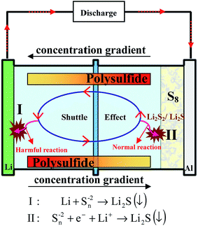
(1) “Shuttle effect”: the intermediate long-chain lithium polysulfide species dissolve instantly into electrolytes. Thereby, the dissolved polysulfide species can diffuse from the cathode to the lithium anode and then return to the sulfur cathode with the change of the concentration gradient, leading to the well-known shuttle effect (Fig. 4). During this diffusion, the soluble polysulfide species can be directly reduced by Li metal without electrons present to form short-chain polysulfides (Li2S2/Li2S). Then these insoluble Li2S2/Li2S will be deposited on Li metal and cannot be used in the following cycles, thus giving rise to a severe loss of active materials of the cathode, and high self-discharge and rapid capacity decay of the sulfur cathode. However, it should be noted that the soluble polysulfide can ensure the fast kinetics of this process (S8 → Li2S8 → Li2S6/Li2S4), leading to a high utilization of sulfur. This is because no insulating layer is formed on the surface of the conductive material with the dissolution of insulating polysulfide, guaranteeing the electron conductivity of the cathode in this process.
(2) “Low utilization of sulfur”: the insulating nature of sulfur and lithium sulfide results in a very low utilization of sulfur, especially during the process Li2S4 → Li2S2/Li2S providing the major capacity of Li–S batteries. The generated insoluble and insulating Li2S2 or Li2S will be deposited on the surface of the conductive material, thus making the reaction kinetics slow, increasing the polarization and leading to inferior utilization of sulfur and poor rate performance.
(3) “Unstable cathode structure”: since the density of sulfur (S8) and lithium sulfide (Li2S) is different (2.03 vs. 1.66 g cm−3, respectively), there is a huge volume fluctuation (∼80%) of sulfur during the discharge/charge process, which leads to an unstable cathode structure. Therefore, the cycle performance of sulfur cathodes is not only affected by the shuttle effect but also by the volume expansion.
The reaction of sulfur also suggests that S8 obtains electrons during the discharge process,7 which is almost similar to that of anode materials (C, Si, etc.) of LIBs, indicating that it is necessary to use Li metal as the anode in LSBs.12 Therefore, the challenges of a Li metal anode also hinder the practical application of LSBs. These issues of metallic Li anodes are caused by Li dendrites (Fig. 5), which are inevitably generated during the charge/discharge process due to repetitive Li plating/stripping at the electrode surface.22–24 These drawbacks are listed as follows:
(1) “Low coulombic efficiency”: Li metal can react with the electrolyte directly to form a passivating film on the Li metal/electrolyte interface known as the solid electrolyte interface (SEI); note that the SEI can allow Li-ion transmission but does not permit electron transport (step 1 in Fig. 5). However, the SEI is easily cracked because of the huge volume expansion caused by the formation of Li dendrites (step 2 in Fig. 5). Consequently, this SEI layer is unable to protect the Li metal anode from the undesirable and irreversible reactions with the electrolyte, leading to continuous consumption of both Li metal and the electrolyte, thus giving rise to poor reversibility and low coulombic efficiency.
(2) “Low safety”: with the unceasing growth of Li dendrites, the separator may be penetrated by dendrites (step 3-1 in Fig. 5), resulting in internal short circuits and then leading to serious safety hazards.
(3) “Low utilization of Li”: some dendrites may be fractured during their growing process and then will be completely encapsulated by the SEI, leading to non-contact with the main anode. This part of Li metal is well-known as “dead lithium” since it is unable to be utilized in the following cycling processes (step 3-2 in Fig. 5), leading to low utilization of Li.
(4) “Large polarization”: the Li metal anode always forms porous and uneven structures during further charge–discharge processes (step 4 in Fig. 5), which lead to longer diffusion pathways of Li ions and larger resistance of electrons, thus causing a large polarization of the Li metal anode.
To break down the aforementioned technical barriers in LSB systems, various approaches have been proposed in the past 10 years. Rational design to address the challenges with the sulfur cathode should include the following features:25–27
(a) A strategy to provide high conductivity of the whole sulfur cathode, resulting in desired sulfur utilization;
(b) A method to confine the shuttle effect of lithium polysulfide species, guaranteeing the long cycle life of the sulfur cathode;
(c) A method to accommodate the volume fluctuation (∼80%) of sulfur during the discharge/charge process, ensuring the structural stability of the cathode.
Nowadays, a typical strategy to obtain high performance sulfur cathodes is the use of various structural host materials (such as carbon materials,28–31 polar metal oxides and sulfides,32–35 conducting polymers36–38 and their composites39–41), which could improve the conductivity and confine lithium polysulfide species through physical/chemical effects. These host materials have their own advantages and disadvantages: carbon materials can significantly improve the utilization of sulfur due to their high conductivity, and somewhat enhance cyclability because they can adsorb polysulfide through weakly physical functions. For example, Li and co-workers designed a sulfur cathode via using amorphous carbon (AC) as the host material, which exhibited a high reversible capacity of 1220 mA h g−1 at 0.1C and an enhanced but unsatisfactory cyclability (68% of the initial capacity retained after 50 cycles);42 in contrast, metal oxides/sulfides can further improve the cycle performance of sulfur cathodes because of their polar nature, and can adsorb polysulfide by strong chemical functions, and somewhat enhance the utilization of sulfur due to their conductivity being higher than that of sulfur but much lower than that of carbon materials. For example, Cui et al. designed and fabricated a sulphur–TiO2 yolk–shell nanoarchitecture with an internal void space to further improve the cycle performance of sulfur cathodes. In this work, the TiO2/S cathode retained 67% of the initial capacity after 1000 cycles, displaying an ultra-long cycle life. However, the initial capacity of this cathode is just 1030 mA h g−1 at 0.5C, which is lower than that using carbon–sulfur composite materials.43
Rational design to address the challenges on the Li anode suppresses dendrite growth effectively. Up to now, there are four typical methods to obtain the high performance Li anode, including:
(a) LiX (X = Al, B, Si, Sn, C, etc.) alloy strategy: this method can suppress the dendrites by storing lithium in the ionic form.44,45 However, its application is limited by the large volume changes during cycling of the LiX alloy (X = Al, B, Si, Sn) or drastically sacrificed capacity of the LiX alloy (X = C);
(b) Li metal/electrolyte interface modification strategy: this method can protect the lithium metal via forming a passivating film on the Li metal/electrolyte interface.46,47 Unfortunately, this passivating film is breakable due to the large volume changes caused by Li dendrites. Therefore, there is an imperative requirement for design of passivating films with high shear modulus or flexibility;
(c) Solid-state electrolyte strategy: this strategy can impede the formation of dendrites because of the high shear modulus of solid-state electrolytes (about twice that of the Li dendrites).48,49 However, the ionic conductivity of solid-state electrolytes (10−8 and 10−5 S cm−1 at room temperature) is typically lower than that of commercial liquid electrolytes (10−3 S cm−1), restricting the application of solid-state electrolytes.
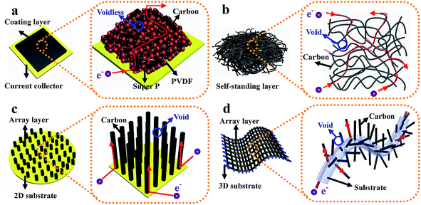
(d) Structured anode design strategy: dendrite-free Li metal anodes can also be achieved by using novel architectures. For instance, Zheng et al. designed interconnected hollow carbon nanospheres on Cu foil to protect the fragile SEI layer, thus leading to dendrite-free anodes.50 Yan and co-authors regulated lithium metal to selectively deposit into hollow carbon spheres (HCS) through the Au nanoparticles loaded inside HCS, which showed no nucleation barriers for Li deposition. Such selective deposition and stable encapsulation of lithium metal eliminated dendrite formation.51 Liang et al. demonstrated that a 3D polymer nanofiber structure was capable of homogenizing the distribution of electrons/thermodynamics, thus hindering dendrite formation.52 The above discussion suggests that effective improvement of the overall device performance of LSBs can be realized by various superior architecture designs of electrodes. Among these architectures, binder-free electrode structures are verified to be one of the most effective strategies because they have some characteristics of this type of structure which are different from those of electrodes with binders.53,54 As shown in Fig. 6a, for traditional powder electrodes, the insulating binder particles (such as polyvinylidene fluoride, sodium alginate, and so on) will impede the continuous transmission path of electrons, especially in powder electrodes with insulating active materials (for example sulfur). Conversely, in binder-free electrodes (such as self-standing films, array structures on different substrates, etc. displayed in Fig. 6b–d): (1) the interlinked architecture not only shortens transport distances for ions in the well-interconnected structure, but also provides a continuous pathway for fast electron transport, thus ensuring the fast kinetics of these binder-free electrodes; (2) the abundant structural space can ensure that this structure loads sufficient active materials and that there is adequate contact between active materials and the electrolyte, leading to a high-performance electrode with large areal loading of active materials; (3) this structure provides a large electrochemically active surface area where electrons and Li ions can come into contact with the active materials for fast conversion reactions due to the continuous pathways and abundant exposed surface area, leading to high utilization of active materials; (4) abundant structural voids between neighboring nanostructures can provide enough space to accommodate the significant volume changes of active materials during the charge–discharge process. Therefore, it is urgent to review recent advances in this direction to promote the fundamental and technical advancements of LSBs.
In this review, we aim to provide a comprehensive review of recent advancements in the field of LSBs with binder-free electrode structures. First, we present the recent advances in sulfur cathodes by using binder-free structures and point out advantages and challenges (Section 1). Next, we review the recently proposed strategies to suppress dendrite growth via using binder-free structures and highlight the functions of these structures (Section 2). We end the review with an outlook and proposal of several possible improvement trends to further design the binder-free structured electrodes for LSBs.
2. Binder-free structure for sulfur cathodes
2.1 Self-standing film
Self-standing films with large inter-spaces and low manufacturing costs have some advantages for sulfur cathodes:55–62 (1) the effect of insulating sulfur and its insoluble discharge products (Li2S2/Li2S) on electron transport in sulfur cathodes can be mitigated through a continuous pathway for fast electron transport provided by the interlinked architecture; (2) this structure provides large electrochemically active surface areas where electrons and Li ions can come into contact with the sulfur for fast conversion reactions; (3) the abundant structural space accommodates the significant volume changes of sulfur during the charge/discharge process. Therefore, the sulfur cathode using host materials with a binder-free film structure exhibits superior electrochemical performance.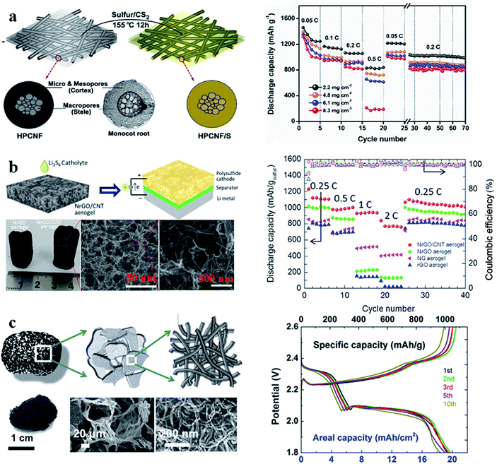 | ||
| Fig. 7 (a) Schematic illustration of the synthesis of the S/HPCNF cathode and its rate performance; (b) schematic illustration and characterization of the sulfur/r-GO/CNT hybrid cathode and its rate performance; (c) schematic illustration and characterization of 3D CNT foam and the galvanostatic charge/discharge curves of the sulfur-3D CNT foam at 0.1C. (a) Reproduced with permission.68 Copyright 2018, Elsevier; (b) reproduced with permission.69 Copyright 2016, Elsevier; (c) reproduced with permission.70 Copyright 2017, American Chemical Society. | ||
The performance of sulfur cathodes can be further improved via more elaborate structural design. For example, Zhu et al. demonstrated that a sulfur cathode with interconnected carbon nanotube/graphene nanosphere scaffolds (Fig. 8a–c) can show a high sulfur utilization of 81% (corresponding to 1346 mA h g−1) at a current rate of 0.1C.71 Liu et al. synthesized a CNT-threaded nitrogen-doped porous carbon film (Fig. 8d–f), which can improve the sulfur cathode capacity to 1057 mA h g−1 at 0.2C with a high sulfur-loading of 6.9 mg cm−2.72
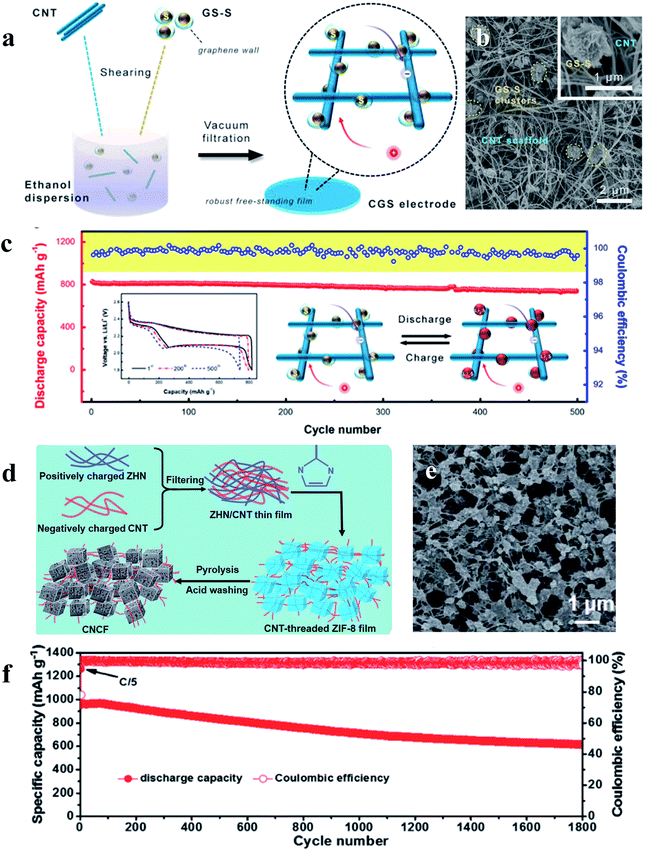 | ||
| Fig. 8 (a–c) Schematic illustration, characterization and the cycle performance (0.5C) of the sulfur cathode with interconnected carbon nanotube/graphene nanosphere scaffolds; (d–f) schematic illustration, characterization and the cycle performance (1C) of the sulfur cathode with CNT-threaded nitrogen-doped porous carbon films. (a–c) Reproduced with permission.71 Copyright 2018, Royal Society of Chemistry; (d–f) reproduced with permission.72 Copyright 2016, Elsevier. | ||
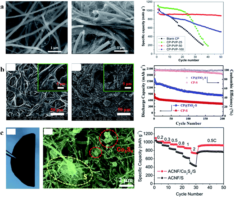 | ||
| Fig. 9 (a) Characterization of CP and CP-PVP and the cyclability of the sulfur cathode with CP and CP-PVP at 0.01C; (b) characterization of CP and CP@TiO2 and cycling performances of the sulfur cathode with CP and CP@TiO2 at 0.5C; (c) characterization of S/Co3S4 on the ACNF cathode and its rate performances. (a) Reproduced with permission.78 Copyright 2015, American Chemical Society; (b) reproduced with permission.79 Copyright 2015, Elsevier; (c) reproduced with permission.80 Copyright 2017, Elsevier. | ||
2.2 Ordered array film
In addition to the above-mentioned advantages of self-supporting films, ordered array films produce a number of other benefits:81–85 (1) the array structure can provide superior and shorter electron transport routes because the host materials directly grown on the current collector can form ordered electron transport pathways; (2) the array structure with nanostructures aligned on current collectors can lead to uniform distribution of sulfur on host materials, which can further improve the performance of cathodes with large areal sulfur loading; (3) the array structure can form numerous “nano-reservoirs”, and thus can confine polysulfides and minimize the shuttle effect effectively. Therefore, the sulfur cathode using host materials with a binder-free array structure exhibits superior electrochemical performance.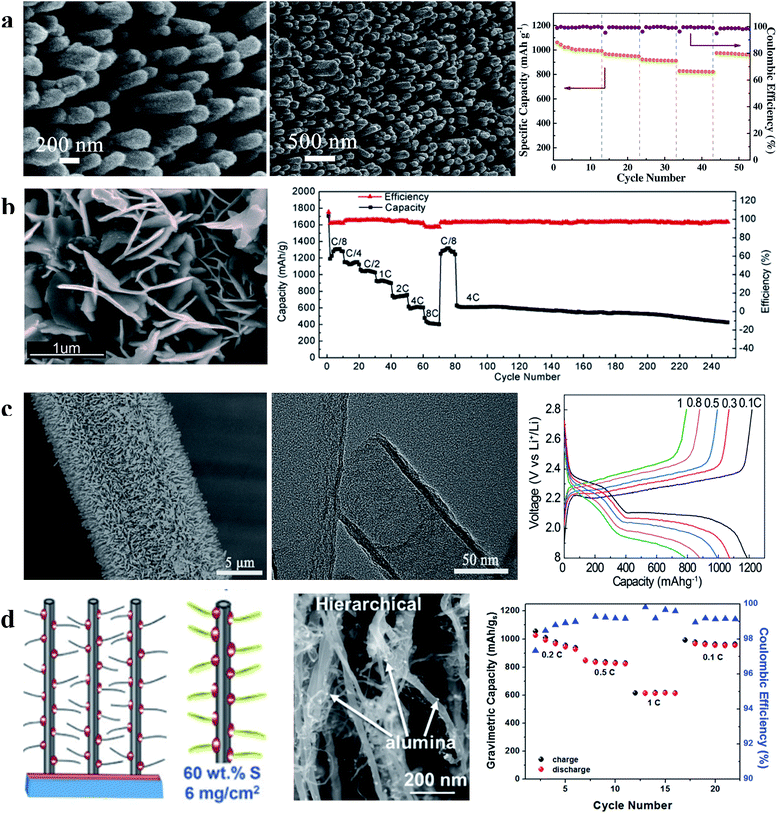 | ||
| Fig. 10 (a) Characterization of the S/CNA cathode and its rate performance; (b) characterization of the S-G NWA cathode and its rate and cycling performances; (c) characterization of CNT arrays on carbon cloth and the first charge–discharge curves of the S/CNT array cathode at different current densities; (d) schematic illustration and characterization of the hierarchical S/CNT array cathode and its rate performance. (a) Reproduced with permission.86 Copyright 2016, Elsevier; (b) reproduced with permission.87 Copyright 2015, American Chemical Society; (c) reproduced with permission.88 Copyright 2016, American Chemical Society; (d) reproduced with permission.89 Copyright 2017, Royal Society of Chemistry. | ||
In addition to the adsorption strategy, recently, an imprisonment strategy has been developed using a facilely formed solid electrolyte interface (SEI) as a smart blocking layer.90 This SEI layer can suppress the shuttle effect while allowing lithium ions to pass through, thus improving the cycle stability of sulfur cathodes and ensuring sulfur utilization. Nevertheless, the insulating blocking layer slightly decreases the coulombic efficiency of the electrode (∼95%) because electron transport in the powder electrode will affect the efficiency of this layer (Fig. 11a). This issue can be further solved by using an array structure because such a structure could provide ordered electron transport pathways. As illustrated in Fig. 11b, the cathode with a three-dimensional CNT array structure on carbon cloth (morphology characterization displayed in Fig. 11c and d) allows electron transport from the carbon cloth to the CNTs and sulfur without passing through the SEI layer. As a result, the SEI-wrapped CNT/sulfur array cathode simultaneously demonstrates high coulombic efficiency (∼99%) and good cycle stability (81.4% capacity retention after 200 cycles), indicating that the array structure is very suitable for the imprisonment strategy, as shown in Fig. 11e.
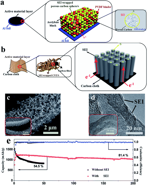 | ||
| Fig. 11 (a) Schematic diagrams of the pathway of electron transport in a powder structured electrode (a) and in an array structured electrode (b); morphology of the SEI wrapped CNT/S array electrode: (c) SEM and (d) TEM; (e) cycle performance of the SEI wrapped CNT/S array electrode at 0.2C. Reproduced with permission.90 Copyright 2017, Wiley-VCH. | ||
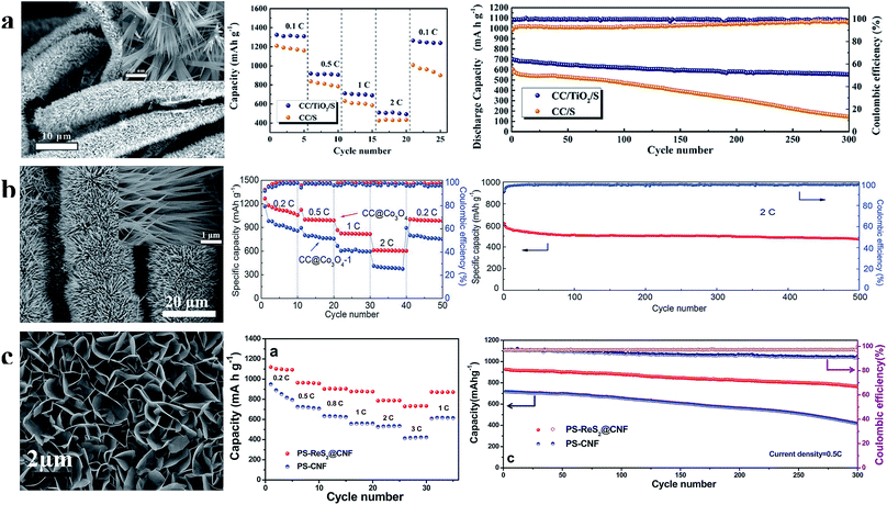 | ||
| Fig. 12 (a) Characterization of the TiO2 nanowire array and the rate and cycle performance at 1C of the S/TiO2 nanowire array cathode; (b) characterization of the Co3O4 nanoneedle array and the rate and cycle performance at 2C of the sulfur cathode prepared using the Co3O4 nanoneedle array; (c) characterization of the ReS2 nanosheet array and the rate and cycle performance at 0.5C of the S/ReS2 nanosheet array cathode. (a) Reproduced with permission.95 Copyright 2018, Elsevier; (b) reproduced with permission.96 Copyright 2017, Royal Society of Chemistry; (c) reproduced with permission.97 Copyright 2016, American Chemical Society. | ||
3. Binder-free structure for Li-metal anodes
Binder-free films have some unique properties for Li metal anode design, such as a high electrochemical surface area and high electric conductivity, which can decrease the effective current density for Li-metal deposition/dissolution.98–100 Moreover, with a suitable porous structure, binder-free films can accumulate Li deposits within its internal space, thus minimizing the possibility of undesired dendritic growth of Li-metal.101–103 Therefore, it is well recognized that lithium metal electrodes with a self-standing film host structure has practical values for future applications.104–1063.1 Three-dimensional conductive material (carbon, metal) network binder-free film
According to the work reported by Yang et al., the 3D current collector can optimize the deposition behaviour of Li significantly due to its submicron skeleton and high electroactive surface area, thus restricting the formation of Li dendrites. As shown in Fig. 13a, the submicron skeleton of 3D Cu could make the electric field uniform because the submicron skeleton of the 3D Cu foil can adjust the charge centers and nucleation sites, leading to homogeneous dispersion of Li (Fig. 13b and c). With the advantages of a 3D current collector, the Li anode designed in this work could be stably cycled without short circuit and large voltage hysteresis for 600 h (Fig. 13d).107 Zuo et al. showed that multifunctional 3D current collectors (Fig. 13e) could effectively improve the electrochemical performance due to the following advantages: (1) the interlinked carbon fibers with large surface area can lower the local current density, giving rise to more uniform electrochemical deposition of Li; (2) the porous structure of the 3D current collector has enough space to mitigate Li plating/stripping processes. The Li anode with this versatile 3D current collector in this work displayed an areal capacity as high as 8 mA h cm−2 without obvious dendrite formation (as Fig. 13f and g shows) and ran for 300 h without large voltage hysteresis (Fig. 13h).108 Therefore, various types of 3D network electrodes with different carbon/metal materials have been reported recently, including carbon materials,109,110 Cu111,112 and Ni,113 which have been employed as host frameworks to accommodate lithium storage.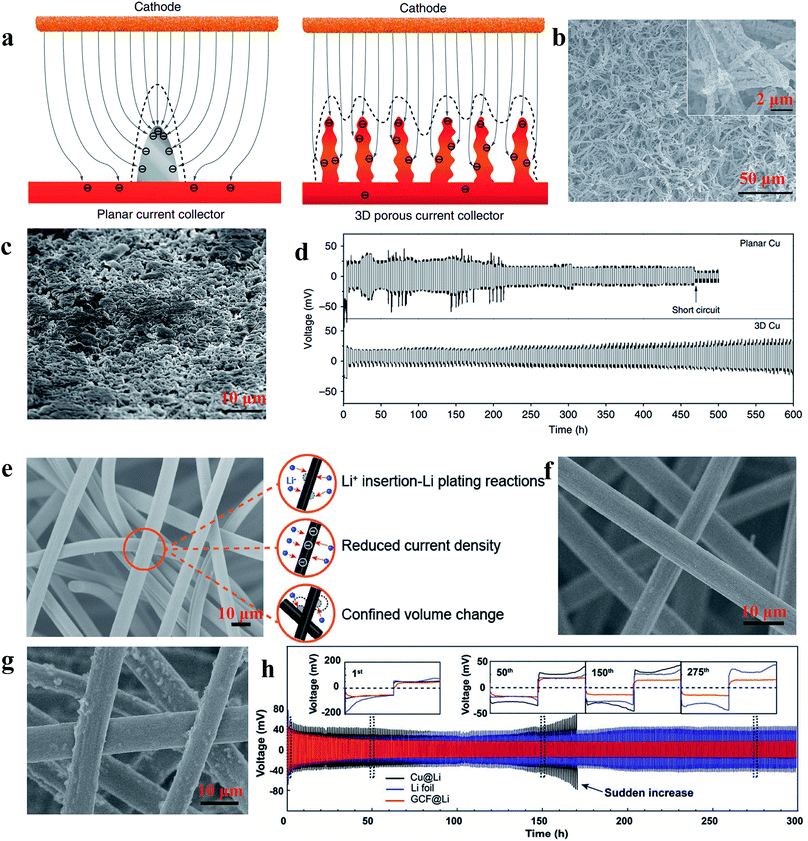 | ||
| Fig. 13 (a) Illustration of the proposed electrochemical deposition processes of Li metal on the planar current collector and 3D current collector; SEM images of 3D Cu foil (b) and 3D Cu foil with 2 mA h cm−2 of Li loading (c); (d) voltage profiles of Li metal plating/stripping at 0.2 mA h cm−2 on different current collectors; (e) illustration of the versatility of the 3D GCF structure; SEM images of 3D GCF (f) and 3D GCF with 8 mA h cm−2 of Li loading (g); (h) galvanostatic plating/stripping profiles on different current collectors. (a–d) Reproduced with permission.107 Copyright 2015, Nature Publishing Group; (e and f) Reproduced with permission.108 Copyright 2017, Wiley-VCH. | ||
3.2 Three-dimensional hybrid material network binder-free film
Although the Li anodes with a 3D conductive material network architecture displayed superior electrochemical performance in many previous studies, the Li wettability on the surface of hosts still restricts the further improvement of Li anodes.114–116 To address this issue, surface-modified 3D host material network structures within lithiophilic materials have been developed to enhance the wetting properties between metallic lithium and host materials, leading to superior electrochemical performances during lithium plating/stripping.117–120 Yang et al. utilized silver nanoparticle (AgNP) modified 3D carbon nanofibers (CNFs) to impede the formation of Li dendrites. As shown in Fig. 14a, since Ag has an appreciable solubility in Li according to the Li–Ag phase diagram, Ag nanoseeds could guide more uniform deposition of Li on CNFs, which can be confirmed by the SEM comparison of 1 mA h cm−2 of Li deposited on CNFs with AgNPs (Fig. 14b) and CNFs (Fig. 14c).121 According to Jin et al., a ZnO modified 3D hierarchical porous carbon (HCP) scaffold also could lead to more uniform deposition of Li (Fig. 14d). This is because Li ions prefer to react with ZnO seeds (Li+ + ZnO → Li2O + Zn) during the initial process, thus resulting in the formation of Zn, which is soluble in Li according to the phase diagrams. Therefore, the existence of Zn induced the promising deposition of Li on the 3D HCP, leading to a dendrite-free Li metal anode (Fig. 14e and f).122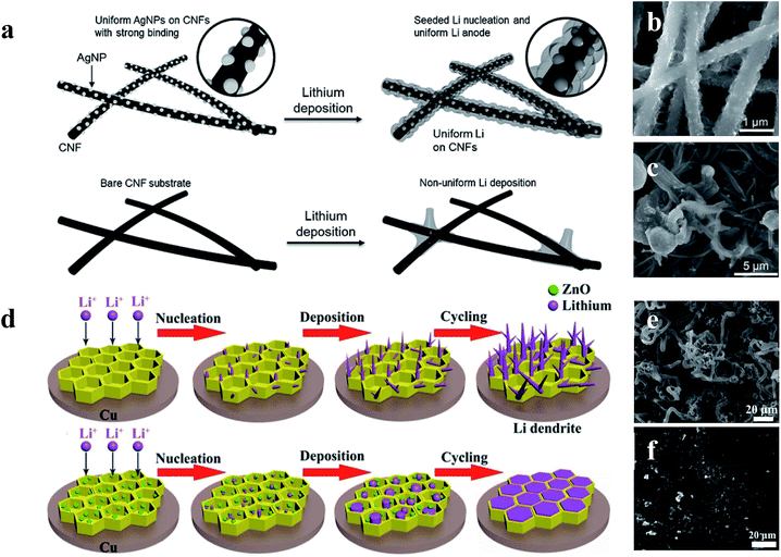 | ||
| Fig. 14 (a) Schematic diagrams of the comparison between Li deposition on CNFs and CNFs with AgNPs; SEM images of 1 mA h cm−2 of Li deposited on CNFs with AgNPs (b) and CNFs (c); (d) schematic diagrams of the comparison between Li deposition within the HCP scaffold with and without the decoration of ZnO nanoparticles; SEM images of HCP (e) and ZnO@HPC electrodes (f) after 80 cycles at 1 mA cm−2 with a Li stripping/plating capacity of 1 mA h cm−2. (a–c) Reproduced with permission.121 Copyright 2017, Wiley-VCH; (d–f) reproduced with permission.122 Copyright 2017, Elsevier. | ||
To find the materials which can enhance the wetting properties between metallic lithium and host materials, Yan et al. did a very meaningful study which measured the overpotential during Li deposition on various substrates. The results are provided in Fig. 15a and b. This study confirmed that Li metal nucleation overpotential on materials with definite solubility (Pt, Al, Mg, Zn, Ag and Au) in Li was essentially zero, leading to preferential Li metal deposition. Materials showing no solubility (Cu, Ni, C, Sn, and Si) in lithium were also tested, and the results suggested that all five materials show a clear overpotential for Li metal nucleation, and form compound alloy phases with Li. Therefore, according to these studies, the selective deposition of Li through heterogeneous seeded growth can be realized, which is significant for further modification of binder-free structured Li metal anodes.123
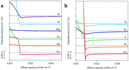 | ||
| Fig. 15 (a) Voltage profiles of various materials with some solubility in Li during Li deposition at a current density of 10 μA cm−2; (b) shifted voltage profiles of various materials with negligible solubility in Li during Li deposition at a current density of 10 μA cm−2; the horizontal gray lines show 0 V versus Li in (a) and (b). (a–c) Reproduced with permission.123 Copyright 2016, Nature Publishing Group. | ||
Zuo et al. provided an alternative way to address this issue, via hollow silica microspheres (HSMS) with a carbon nanotube (CNT) core architecture (Fig. 16). In this structure, the insulating coating layer prevents Li ions from acquiring electrons on the CNTs and thus guiding the selective deposition of Li in HSMS, giving rise to dendrite-free growth (Fig. 16a–c). The anode designed using this strategy maintained a high coulombic efficiency during 300 cycles even at a current density of 0.2 mA cm−2 or a higher one of 0.5 mA cm−2 with a total capacity of 2 mA h cm−2 (Fig. 16d).124 However, there is no ordered transmission path for electrons in the powder electrode, leading to complex or defective control of electrons. Therefore, the array structure which can optimize the transmission path of electrons has a very broad application prospect in this strategy. For example, Guo et al. designed an SEI wrapped tubular carbon array (TCA) structure to improve the performance of lithium metal anodes via an electron regulation strategy (Fig. 17a–c). In this structure, electrons can be transported directly to tubular carbon without passing through the SEI, thus guiding selective Li deposition on the inner-surface of tubular carbon, leading to dendrite-free growth (Fig. 17d). The anode designed using this strategy (SEI wrapped TCA electrode) maintained a higher and more stable coulombic efficiency during 200 cycles compared with the electrode without SEI wrapping (TCA electrode) or the powder electrode (TCP electrode), indicating that the array structure is very helpful.125
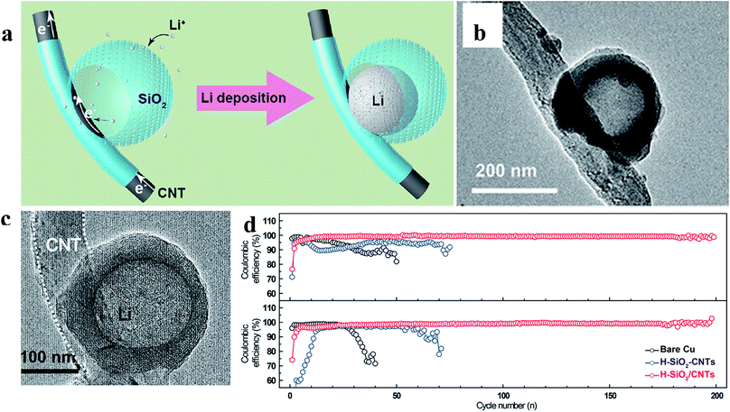 | ||
| Fig. 16 (a) Illustration of the proposed electrochemical deposition processes of Li metal on HSMS with a CNT core architecture; TEM images of HSMS with a CNT core structure (b) and the structure after Li deposition (c); (d) cycle performance of Li metal plating/stripping at 0.2 and 0.5 mA cm−2 with a total capacity of 2 mA h cm−2. (a–d) Reproduced with permission.124 Copyright 2017, American Chemical Society. | ||
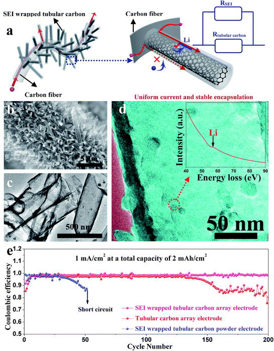 | ||
| Fig. 17 (a) Illustration of electron transport pathways and Li plating in the SEI wrapped TCA electrode; (b) SEM image and (c) TEM image of the TCA structure; (d) TEM image of tubular carbon in the TCA electrode after cycling; the inset is the corresponding EELS spectra; (e) coulombic efficiencies of Li metal plating/stripping in different electrodes at 1 mA cm−2 with a total capacity of 2 mA h cm−2. (a–d) Reproduced with permission.125 Copyright 2019, Royal Society of Chemistry. | ||
4. Conclusions and outlook
In conclusion, the recent advances in design and fabrication of binder-free architectures as state-of-the-art electrodes for LSBs have been summarized and the following conclusions can be drawn:(1) Although both the binder-free 3D self-standing film and array film can improve the performance of LSBs, there are different priorities of their functions. For example, the array film is particularly suitable for addressing the issue of sulfur cathodes with polar metal oxides and sulfides, since the array structure can provide better electron transport paths compared with the 3D self-supporting structure. Compared with the strategy of compositing with the electric conduction materials, this method is not only simple, but also does not increase the amount of inactive materials which is essential for the energy density of the whole cathode. Similarly, the array structure can make the current distribution more uniform than the 3D self-standing film because of the better electron transport paths in array films, and thus effectively inhibiting the formation of lithium dendrites. However, large-scale preparation of array films is more difficult than that of self-standing films, which without the substrate also can make the sulfur cathode or Li anode maintain larger energy density.
(2) Although sufficient space between materials in binder-free films can effectively accommodate the high volume expansion of sulfur/lithium, these films with an open architecture, especially array structure films, fail to imprison sulfur/lithium significantly compared with electrodes with closed structures (like hollow spheres).
(3) The method to inhibit dendrite formation via controlling Li ions receiving electrons at a specified place is a very significant new direction for designing Li metal anodes. However, there is no ordered transmission path for electrons in the powder electrode, leading to a complex or defective regulation of electron transmission. Array structures can provide very ordered transport pathways, leading to easier regulation of electron transmission. Therefore, the array structure has a very broad application prospect in this strategy. However, the carbon materials used in existing studies with low Li wettability restrict the further improvement of Li anodes.
Therefore, although some significant progress has been made, several possible future prospects, which have not received sufficient attention and research, can be drawn from the above conclusions such as:
(1) Large-scale preparation of array structures: although the array structures can be facilely synthesized by using an anodized aluminium oxide (AAO) template, there is still a demand for simpler and more economical ways to prepare array structures on a large scale. For example, with appropriate electric or magnetic fields, array architectures may be prepared by the casting preparation method of the powder electrode.
(2) Encapsulation of the array structure: for example, a porous film formed on the top of array structures can make the “reservoir-like” array structure become a “house-like” array structure. With this “house-like” array structure, better imprisonment of sulfur/lithium loading in the gaps can be realized, suggesting that films with encapsulation of the array structure can accommodate higher sulfur/lithium loading. It should be noted that the formation of this film must be simple, preferably in one step, to ensure the applicability of the method.
(3) The array structure with lithiophilic materials: to further develop the electron regulation strategy, the carbon array structure should be replaced by cheap lithiophilic materials with high electrical conductivity: (1) the cheap materials can ensure the economy of this strategy; (2) the high conductivity of materials (compared with the coating layer) can guarantee that electrons merely pass along the inner surface of the array structure; (3) the Li wettability of materials can lead to easier deposition of Li metal.
Conflicts of interest
There are no conflicts to declare.Acknowledgements
This work was supported by grants from the National Natural Science Foundation of China (Grant No. 51672205, 51872104 and 21673169), the National Key R&D Program of China (Grant No. 2016YFA0202602), the Research Start-Up Fund from Wuhan University of Technology, and the Fundamental Research Funds for the Central Universities (WUT: 2016IVA083, 2017IB005, and 185220011). In addition, Junling Guo would like to thank his wife for taking care of their four-month-old child alone during the period of preparing this work.Notes and references
- J. Tarascon and M. Armand, Nature, 2001, 414, 359–367 CrossRef CAS PubMed.
- P. G. Bruce, B. Scrosati and J. M. Tarascon, Angew. Chem., Int. Ed., 2008, 47, 2930–2946 CrossRef CAS PubMed.
- V. Etacheri, R. Marom, R. Elazari, G. Salitra and D. Aurbach, Energy Environ. Sci., 2011, 4, 3243–3262 RSC.
- M. M. Thackeray, C. Wolverton and E. D. Isaacs, Energy Environ. Sci., 2012, 5, 7854–7863 RSC.
- L. Kong, C. Yan, J. Q. Huang, M. Q. Zhao, M. M. Titirici, R. Xiang and Q. Zhang, Energy Environ. Mater., 2018, 1, 100–112 CrossRef CAS.
- S. S. Zhang, J. Power Sources, 2007, 164, 351–364 CrossRef CAS.
- W. Guo and Y. Z. Fu, Energy Environ. Mater., 2018, 1, 20–27 CrossRef CAS.
- A. Manthiram, Y. Fu and Y.-S. Su, Acc. Chem. Res., 2012, 46, 1125–1134 CrossRef PubMed.
- A. Manthiram, Y. Fu, S.-H. Chung, C. Zu and Y.-S. Su, Chem. Rev., 2014, 114, 11751–11787 CrossRef CAS PubMed.
- M. A. Hannan, M. S. H. Lipu, A. Hussain and A. Mohamed, Renewable Sustainable Energy Rev., 2017, 78, 834–854 CrossRef.
- K. Xu, Chem. Rev., 2004, 104, 4303–4417 CrossRef CAS PubMed.
- D. Bresser, S. Passerini and B. Scrosati, Chem. Commun., 2013, 49, 10545–10562 RSC.
- M. Wild, L. O'Neill, T. Zhang, R. Purkayastha, G. Minton, M. Marinescu and G. Offer, Energy Environ. Sci., 2015, 8, 3477–3494 RSC.
- J. Guo, Z. Yang, Y. Yu, H. c. D. Abruña and L. A. Archer, J. Am. Chem. Soc., 2012, 135, 763–767 CrossRef PubMed.
- P. G. Bruce, S. A. Freunberger, L. J. Hardwick and J. M. Tarascon, Nat. Mater., 2011, 11, 19–29 CrossRef PubMed.
- Z. W. Seh, Y. Sun, Q. Zhang and Y. Cui, Chem. Soc. Rev., 2016, 45, 5605–5634 RSC.
- X. Liu, J. Q. Huang, Q. Zhang and L. Mai, Adv. Mater., 2017, 29, 1601759–1601784 CrossRef PubMed.
- J. Wang, J. Yang, C. Wan, K. Du, J. Xie and N. Xu, Adv. Funct. Mater., 2003, 13, 487–492 CrossRef CAS.
- J. Tan, D. Liu, X. Xu and L. Mai, Nanoscale, 2017, 48, 19001–19016 RSC.
- L. Kong, H. J. Peng, J. Q. Huang and Q. Zhang, Nano Res., 2017, 10, 4027–4054 CrossRef CAS.
- X. Yu and A. Manthiram, Acc. Chem. Res., 2017, 11, 2653–2660 CrossRef PubMed.
- X. B. Cheng, R. Zhang, C. Z. Zhao and Q. Zhang, Chem. Rev., 2017, 117, 10403–10473 CrossRef CAS PubMed.
- Y. Guo, H. Li and T. Zhai, Adv. Mater., 2017, 29, 1700007–1700031 CrossRef PubMed.
- D. Lin, Y. Liu and Y. Cui, Nat. Nanotechnol., 2017, 12, 194–206 CrossRef CAS PubMed.
- H. J. Peng, J. Q. Huang and Q. Zhang, Chem. Soc. Rev., 2017, 46, 5237–5288 RSC.
- H. J. Peng, J. Q. Huang, X. B. Cheng and Q. Zhang, Adv. Energy Mater., 2017, 7, 1700260 CrossRef.
- M. Liu, X. Qin, Y. B. He, B. Li and F. Kang, J. Mater. Chem. A, 2017, 5, 5222–5234 RSC.
- J. Hu, T. Zhao, X. Ji, X. Peng, W. Jin, W. Yang, L. Zhang, J. Gao, A. Dang and H. Li, Chem. Phys. Lett., 2017, 688, 59–65 CrossRef CAS.
- C. Zhang, H. B. Wu, C. Yuan, Z. Guo and X. W. Lou, Angew. Chem., Int. Ed., 2012, 124, 9730–9733 CrossRef.
- Z. Zhang, H. K. Jing, S. Liu, G. R. Li and X. P. Gao, J. Mater. Chem. A, 2015, 3, 6827–6834 RSC.
- H. Wang, Y. Yang, Y. Liang, J. T. Robinson, Y. Li, A. Jackson, Y. Cui and H. Dai, Nano Lett., 2011, 11, 2644–2649 CrossRef CAS PubMed.
- X. Liang, C. Hart, Q. Pang, A. Garsuch, T. Weiss and L. F. Nazar, Nat. Commun., 2015, 6, 5682–5690 CrossRef PubMed.
- Z. Xu, H. Wang, Z. Li, A. Kohandehghan, J. Ding, J. Chen, K. Cui and D. Mitlin, J. Phys. Chem. C, 2014, 118, 18387–18396 CrossRef CAS.
- J. Xu, W. Zhang, H. Fan, F. Cheng, D. Su and G. Wang, Nano Energy, 2018, 51, 73–82 CrossRef CAS.
- T. Chen, L. Ma, B. Cheng, R. Chen, Y. Hu, G. Zhu, Y. Wang, J. Liang, Z. Tie, J. Liu and Z. Jin, Nano Energy, 2017, 38, 239–248 CrossRef CAS.
- L. Xiao, Y. Cao, J. Xiao, B. Schwenzer, M. H. Engelhard, L. V. Saraf, Z. Nie, G. J. Exarhos and J. Liu, Adv. Mater., 2012, 24, 1176–1181 CrossRef CAS PubMed.
- Y. Fu and A. Manthiram, Chem. Mater., 2012, 24, 3081–3087 CrossRef CAS.
- F. Wu, J. Chen, R. Chen, S. Wu, L. Li, S. Chen and T. Zhao, J. Phys. Chem. C, 2011, 115, 6057–6063 CrossRef CAS.
- M. Yu, J. Ma, H. Song, A. Wang, F. Tian, Y. Wang, H. Qiu and R. Wang, Energy Environ. Sci., 2016, 9, 1495–1503 RSC.
- Z. Li, J. Zhang and X. W. Lou, Angew. Chem., Int. Ed., 2015, 54, 12886–12890 CrossRef CAS PubMed.
- J. Zhang, Y. Shi, Y. Ding, W. Zhang and G. Yu, Nano Lett., 2016, 16, 7276–7281 CrossRef CAS PubMed.
- K. Li, B. Wang, D. Su, J. Park, H. Ahn and G. Wang, J. Power Sources, 2012, 202, 389–393 CrossRef CAS.
- S. Z. Wei, W. Li, J. J. Cha, G. Zheng, Y. Yang, M. T. Mcdowell, P. C. Hsu and Y. Cui, Nat. Commun., 2013, 4, 1331–1336 CrossRef PubMed.
- G. Zheng, S. W. Lee, Z. Liang, H. W. Lee, K. Yan, H. Yao, H. Wang, W. Li, S. Chu and Y. Cui, Nat. Nanotechnol., 2014, 9, 618–623 CrossRef CAS PubMed.
- K. Yan, Z. Lu, H. W. Lee, F. Xiong, P. C. Hsu, Y. Li, J. Zhao, S. Chu and Y. Cui, Nat. Energy, 2016, 1, 16010–16018 CrossRef CAS.
- N. W. Li, Y. X. Yin, C. P. Yang and Y. G. Guo, Adv. Mater., 2016, 28, 1853–1858 CrossRef CAS PubMed.
- C. K. Chan, H. Peng, G. Liu, K. McIlwrath, X. F. Zhang, R. A. Huggins and Y. Cui, Nat. Nanotechnol., 2008, 3, 31–35 CrossRef CAS PubMed.
- N. Liu, Z. Lu, J. Zhao, M. T. McDowell, H. W. Lee, W. Zhao and Y. Cui, Nat. Nanotechnol., 2014, 9, 187–192 CrossRef CAS PubMed.
- W. Liu, N. Liu, J. Sun, P. C. Hsu, Y. Li, H. W. Lee and Y. Cui, Nano Lett., 2015, 15, 2740–2745 CrossRef CAS PubMed.
- G. Zheng, C. Wang, A. Pei, J. Lopez, F. Shi, Z. Chen, A. D. Sendek, H. W. Lee, Z. Lu and H. Schneider, ACS Energy Lett., 2016, 1, 1247–1255 CrossRef CAS.
- K. Fu, Y. Gong, G. T. Hitz, D. W. McOwen, Y. Li, S. Xu, Y. Wen, L. Zhang, C. Wang, G. Pastel, J. Dai, B. Liu, H. Xie, Y. Yao, E. D. Wachsman and L. Hu, Energy Environ. Sci., 2017, 10, 1568–1575 RSC.
- Z. Liang, G. Zheng, C. Liu, N. Liu, W. Li, K. Yan, H. Yao, P. C. Hsu, S. Chu and Y. Cui, Nano Lett., 2015, 15, 2910–2916 CrossRef CAS PubMed.
- J. Jiang, Y. Li, J. Liu, X. Huang, C. Yuan and X. W. Lou, Adv. Mater., 2012, 24, 5166–5180 CrossRef CAS PubMed.
- K. Liang, L. Li and Y. Yang, ACS Energy Lett., 2017, 2, 373–390 CrossRef CAS.
- R. Ummethala, M. Fritzsche, T. Jaumann, J. Balach, S. Oswald, R. Nowak, N. Sobczak, I. Kaban, M. H. Rümmeli and L. Giebeler, Energy Storage Materials, 2018, 10, 206–215 CrossRef.
- B. Li, S. Li, J. Xu and S. Yang, Energy Environ. Sci., 2016, 9, 2025–2030 RSC.
- C. Zu, Y. Fu and A. Manthiram, J. Mater. Chem. A, 2013, 1, 10362–10367 RSC.
- J. Yan, X. Liu, H. Qi, W. Li, Y. Zhou, M. Yao and B. Li, Chem. Mater., 2015, 27, 6394–6401 CrossRef CAS.
- Y. Huang, M. Zheng, Z. Lin, B. Zhao, S. Zhang, J. Yang, C. Zhu, H. Zhang, D. Sun and Y. Shi, J. Mater. Chem. A, 2015, 3, 10910–10918 RSC.
- M. Rao, X. Song and E. J. Cairns, J. Power Sources, 2012, 205, 474–478 CrossRef CAS.
- H. Kim, J. T. Lee and G. Yushin, J. Power Sources, 2013, 226, 256–265 CrossRef CAS.
- M. Wu, Y. Cui and Y. Fu, ACS Appl. Mater. Interfaces, 2015, 7, 21479–21486 CrossRef CAS PubMed.
- L. Sun, D. Wang, Y. Luo, K. Wang, W. Kong, Y. Wu, L. Zhang, K. Jiang, Q. Li, Y. Zhang, J. Wang and S. Fan, ACS Nano, 2016, 10, 1300–1308 CrossRef CAS PubMed.
- Z. Yuan, H.-J. Peng, J.-Q. Huang, X.-Y. Liu, D.-W. Wang, X.-B. Cheng and Q. Zhang, Adv. Funct. Mater., 2014, 24, 6105–6112 CrossRef CAS.
- H. Peng, W. Xu, L. Zhu, D. Wang, J. Huang, X. Cheng, Z. Yuan, F. Wei and Q. Zhang, Adv. Funct. Mater., 2016, 26, 6351–6358 CrossRef CAS.
- P.-Y. Zhai, J.-Q. Huang, L. Zhu, J.-L. Shi, W. Zhu and Q. Zhang, Carbon, 2017, 111, 493–501 CrossRef CAS.
- R. Ummethala, M. Fritzsche, T. Jaumann, J. Balach, S. Oswald, R. Nowak, N. Sobczak, I. Kaban, M. H. Rümmeli and L. Giebeler, Energy Storage Materials, 2018, 10, 206–215 CrossRef.
- X. Zhao, M. Kim, Y. Liu, H.-J. Ahn, K.-W. Kim, K.-K. Cho and J.-H. Ahn, Carbon, 2018, 128, 138–146 CrossRef CAS.
- X. Li, X. Pu, S. Han, M. Liu, C. Du, C. Jiang, X. Huang, T. Liu and W. Hu, Nano Energy, 2016, 30, 193–199 CrossRef CAS.
- M. Li, R. Carter, A. Douglas, L. Oakes and C. L. Pint, ACS Nano, 2017, 11, 4877–4884 CrossRef CAS PubMed.
- L. Zhu, H.-J. Peng, J. Liang, J.-Q. Huang, C.-M. Chen, X. Guo, W. Zhu, P. Li and Q. Zhang, Nano Energy, 2015, 11, 746–755 CrossRef CAS.
- Y. Liu, G. Li, Z. Chen and X. Peng, J. Mater. Chem. A, 2017, 5, 9775–9784 RSC.
- T. Liu, S. Sun, W. Song, X. Sun, Q. Niu, H. Liu, T. Ohsaka and J. Wu, J. Mater. Chem. A, 2018, 6, 23486–23494 RSC.
- M. Zhang, Y. Yang, X. Zhang, M. Cheng, H. Yuan, K. Amin, A. Ahmad, L. Mao, W. Yan and Z. Wei, Adv. Mater. Interfaces, 2018, 5, 1800766 CrossRef.
- X. Han, Y. Xu, X. Chen, Y.-C. Chen, N. Weadock, J. Wan, H. Zhu, Y. Liu, H. Li, G. Rubloff, C. Wang and L. Hu, Nano Energy, 2013, 2, 1197–1206 CrossRef CAS.
- H. Yao, G. Zheng, P. C. Hsu, D. Kong, J. J. Cha, W. Li, Z. W. Seh, M. T. McDowell, K. Yan, Z. Liang, V. K. Narasimhan and Y. Cui, Nat. Commun., 2014, 5, 3943 CrossRef CAS PubMed.
- A. M. Andersson, A. Henningson, H. Siegbahn, U. Jansson and K. Edström, J. Power Sources, 2003, 522, 119–121 Search PubMed.
- Y. Cui and Y. Fu, ACS Appl. Mater. Interfaces, 2015, 7, 20369–20376 CrossRef CAS PubMed.
- Z. Zhang, Q. Li, K. Zhang, W. Chen, Y. Lai and J. Li, J. Power Sources, 2015, 290, 159–167 CrossRef CAS.
- H. Xu and A. Manthiram, Nano Energy, 2017, 33, 124–129 CrossRef CAS.
- S. K. Park, J. Lee, T. Hwang, B. Jang and Y. Piao, ACS Appl. Mater. Interfaces, 2017, 9, 2430–2438 CrossRef CAS PubMed.
- L. Jin, X. Huang, G. Zeng, H. Wu and M. Morbidelli, Sci. Rep., 2016, 6, 32800 CrossRef CAS PubMed.
- P. Li, L. Ma, T. Wu, H. Ye, J. Zhou, F. Zhao, N. Han, Y. Wang, Y. Wu and Y. Li, Adv. Energy Mater., 2018, 8, 1800624 CrossRef.
- G. Zheng, Y. Yang, J. J. Cha, S. S. Hong and Y. Cui, Nano Lett., 2011, 11, 4462–4467 CrossRef CAS PubMed.
- J. Guo, Y. Cai, S. Zhang, S. Chen and F. Zhang, ACS Appl. Mater. Interfaces, 2016, 8, 16116–16124 CrossRef CAS PubMed.
- S. Li, X. Xia, X. Wang and J. Tu, Mater. Res. Bull., 2016, 83, 474–480 CrossRef CAS.
- B. Li, S. Li, J. Liu, B. Wang and S. Yang, Nano Lett., 2015, 15, 3073–3079 CrossRef CAS PubMed.
- X. W. Wu, H. Xie, Q. Deng, H. X. Wang, H. Sheng, Y. X. Yin, W. X. Zhou, R. L. Li and Y. G. Guo, ACS Appl. Mater. Interfaces, 2017, 9, 1553–1561 CrossRef CAS PubMed.
- R. Carter, B. Davis, L. Oakes, M. R. Maschmann and C. L. Pint, Nanoscale, 2017, 9, 15018–15026 RSC.
- J. L. Guo, X. Y. Du, X. L. Zhang, F. X. Zhang and J. P. Liu, Adv. Mater., 2017, 29, 1700273–1700279 CrossRef PubMed.
- W. Zeng, Z. Wang, M. M.-C. Cheng and K. Y. S. Ng, J. Electrochem. Soc., 2018, 165, A1011–A1018 CrossRef CAS.
- Y. Zhao, W. Zhu, G. Z. Chen and E. J. Cairns, J. Power Sources, 2016, 327, 447–456 CrossRef CAS.
- T. Lei, Y. Xie, X. Wang, S. Miao, X. Jie and C. Yan, Small, 2017, 13, 1701013 CrossRef PubMed.
- J. Guo, X. Zhang, X. Du and F. Zhang, J. Mater. Chem. A, 2017, 5, 6447–6454 RSC.
- Y. Yan, T. Lei, Y. Jiao, C. Wu and J. Xiong, Electrochim. Acta, 2018, 264, 20–25 CrossRef CAS.
- Z. Chang, H. Dou, B. Ding, J. Wang, Y. Wang, X. Hao and D. R. MacFarlane, J. Mater. Chem. A, 2017, 5, 250–257 RSC.
- J. Gao, L. Li, J. Tan, H. Sun, B. Li, J. C. Idrobo, C. V. Singh, T. M. Lu and N. Koratkar, Nano Lett., 2016, 16, 3780–3787 CrossRef CAS PubMed.
- Y. Zhao, M. Liu, W. Lv, Y.-B. He, C. Wang, Q. Yun, B. Li, F. Kang and Q.-H. Yang, Nano Energy, 2016, 30, 1–8 CrossRef CAS.
- J. Xiang, Y. Zhao, L. Yuan, C. Chen, Y. Shen, F. Hu, Z. Hao, J. Liu, B. Xu and Y. Huang, Nano Energy, 2017, 42, 262–268 CrossRef CAS.
- S. Matsuda, Y. Kubo, K. Uosaki and S. Nakanishi, Carbon, 2017, 119, 119–123 CrossRef CAS.
- S.-S. Chi, Y. Liu, W.-L. Song, L.-Z. Fan and Q. Zhang, Adv. Funct. Mater., 2017, 27, 1700348 CrossRef.
- Q. Yun, Y. B. He, W. Lv, Y. Zhao, B. Li, F. Kang and Q. H. Yang, Adv. Mater., 2016, 28, 6932–6939 CrossRef CAS PubMed.
- Q. Li, S. Zhu and Y. Lu, Adv. Funct. Mater., 2017, 27, 1606422 CrossRef.
- Y. An, H. Fei, G. Zeng, X. Xu, L. Ci, B. Xi, S. Xiong, J. Feng and Y. Qian, Nano Energy, 2018, 47, 503–511 CrossRef CAS.
- K. Yan, B. Sun, P. Munroe and G. Wang, Energy Storage Materials, 2018, 11, 127–133 CrossRef.
- Q. Li, B. Quan, W. Li, J. Lu, J. Zheng, X. Yu, J. Li and H. Li, Nano Energy, 2018, 45, 463–470 CrossRef CAS.
- C. P. Yang, Y. X. Yin, S. F. Zhang, N. W. Li and Y. G. Guo, Nat. Commun., 2015, 6, 8058–8067 CrossRef CAS PubMed.
- T. T. Zuo, X. W. Wu, C. P. Yang, Y. X. Yin, H. Ye, N. W. Li and Y. G. Guo, Adv. Mater., 2017, 29, 1700389–1700394 CrossRef PubMed.
- Y. J. Zhang, S. F. Liu, X. L. Wang, Y. Zhong, X. H. Xia, J. B. Wu and J. P. Tu, J. Power Sources, 2018, 374, 205–210 CrossRef CAS.
- H. Yu, J. Zhao, L. Ben, Y. Zhan, Y. Wu and X. Huang, ACS Energy Lett., 2017, 2, 1296–1302 CrossRef CAS.
- S. H. Wang, Y. X. Yin, T. T. Zuo, W. Dong, J. Y. Li, J. L. Shi, C. H. Zhang, N. W. Li, C. J. Li and Y. G. Guo, Adv. Mater., 2017, 29, 1703729–1703736 CrossRef PubMed.
- P. Zou, Y. Wang, S. W. Chiang, X. Wang, F. Kang and C. Yang, Nat. Commun., 2018, 9, 464–472 CrossRef PubMed.
- S. Wu, Z. Zhang, M. Lan, S. Yang, J. Cheng, J. Cai, J. Shen, Y. Zhu, K. Zhang and W. Zhang, Adv. Mater., 2018, 30, 1705830 CrossRef PubMed.
- Y. Yang, Z. Wang, T. Jiang, C. Dong, Z. Mao, C. Lu, W. Sun and K. Sun, J. Mater. Chem. A, 2018, 6, 13593–13598 RSC.
- L. Wang, X. Zhu, Y. Guan, J. Zhang, F. Ai, W. Zhang, Y. Xiang, S. Vijayan, G. Li, Y. Huang, G. Cao, Y. Yang and H. Zhang, Energy Storage Materials, 2018, 11, 191–196 CrossRef.
- Y. Xu, A. S. Menon, P. P. R. M. L. Harks, D. C. Hermes, L. A. Haverkate, S. Unnikrishnan and F. M. Mulder, Energy Storage Materials, 2018, 12, 69–78 CrossRef.
- K. Xie, W. Wei, K. Yuan, W. Lu, M. Guo, Z. Li, Q. Song, X. Liu, J. G. Wang and C. Shen, ACS Appl. Mater. Interfaces, 2016, 8, 26091–26097 CrossRef CAS PubMed.
- Y. Liu, D. Lin, Z. Liang, J. Zhao, K. Yan and Y. Cui, Nat. Commun., 2016, 7, 10992–11000 CrossRef CAS PubMed.
- Y. Zhang, B. Liu, E. Hitz, W. Luo, Y. Yao, Y. Li, J. Dai, C. Chen, Y. Wang, C. Yang, H. Li and L. Hu, Nano Res., 2017, 10, 1356–1365 CrossRef CAS.
- R. Zhang, X. R. Chen, X. Chen, X. B. Cheng, X. Q. Zhang, C. Yan and Q. Zhang, Angew. Chem., Int. Ed., 2017, 129, 7764–7768 CrossRef PubMed.
- C. Yang, Y. Yao, S. He, H. Xie, E. Hitz and L. Hu, Adv. Mater., 2017, 29, 1702714–1702721 CrossRef PubMed.
- C. Jin, O. Sheng, J. Luo, H. Yuan, C. Fang, W. Zhang, H. Huang, Y. Gan, Y. Xia, C. Liang, J. Zhang and X. Tao, Nano Energy, 2017, 37, 177–186 CrossRef CAS.
- K. Yan, Z. Lu, H.-W. Lee, F. Xiong, P.-C. Hsu, Y. Li, J. Zhao, S. Chu and Y. Cui, Nat. Energy, 2016, 1, 16010 CrossRef CAS.
- T. T. Zuo, Y. X. Yin, S. H. Wang, P. F. Wang, X. Yang, J. Liu, C. P. Yang and Y. G. Guo, Nano Lett., 2018, 18, 297–301 CrossRef CAS PubMed.
- J. L. Guo, S. P. Zhao, H. Yang, F. X. Zhang and J. P. Liu, J. Mater. Chem. A, 2019, 7, 2184–2191 RSC.
| This journal is © The Royal Society of Chemistry 2019 |

